
Arrowplane
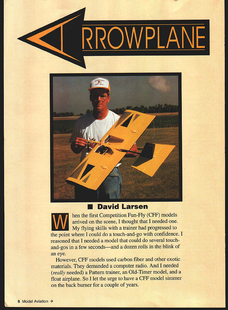
David Larsen
When the first Competition Fun‑Fly (CFF) models arrived on the scene, I thought I needed one. My flying skills with a trainer had progressed to the point where I could do a touch‑and‑go with confidence. I reasoned I needed a model that could do several touch‑and‑gos in a few seconds—and a dozen rolls in the blink of an eye.
However, CFF models used carbon fiber and other exotic materials, demanded a computer radio, and I already wanted a Pattern trainer, an Old‑Timer model, and a float airplane. So I let the urge simmer on the back burner for a couple of years.
In 1995 I decided it was time to satisfy the urge. I had studied the plans and looked at CFF models. I figured I could guesstimate the dimensions and surface areas, but I needed an engine. I had a .40 that wasn't busy and the Fugi .099 from my son's airboat. A .40 is generally considered too big for the average CFF model, so my design would have to fit the Fugi .099.
Two years of fun and 50 test flights later, the prototype Arrowplane is still going strong. I am having a blast with my simple, easy-to-build, inexpensive semi‑CFF model. The airplane was designed to be flown close-in and at low altitudes, so the 36‑inch wingspan has not been a problem. Since most common sizes of balsa come in 36‑inch lengths, the wingspan limit made building easy.
In retrospect, I'm glad I kept the model small. A small model uses a less expensive engine, needs only a miserly amount of fuel, and costs less in wood and covering. An aluminum arrow shaft (from my deer‑hunting hobby) fit the bill as a fuselage.
Do you get the idea I'm a cheapskate? I don't mind having fun with a model that can be built for about $20 and requires two ounces of fuel per flight.
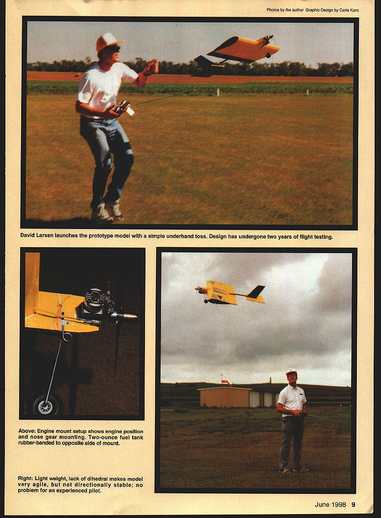
The Arrowplane will ROG (rise off ground) if wire outriggers are installed, but an underhand toss will launch the model even in calm conditions. A dual‑rate radio is desirable for takeoffs and landings, but the real fun happens on high rate. Rolls are very fast, 20‑foot‑diameter loops make flying in a confined area easy, and the model flies slowly enough to let you enjoy the show your thumbs create. (A beginner should save this model until he or she has mastered an aileron trainer.)
Construction
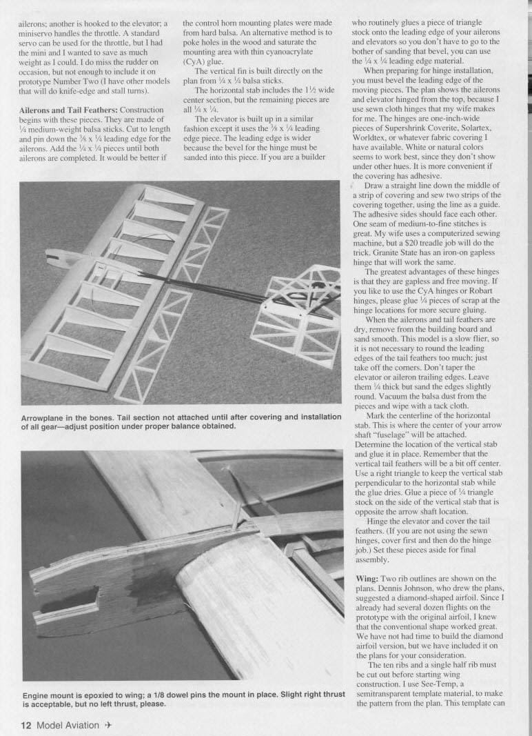
As you study the plans, you'll notice the model is simple. It uses three channels: one standard servo operates the ailerons, another is hooked to the elevator, and a mini‑servo handles the throttle. A standard servo can be used for throttle, but using a mini‑servo saves weight. The prototype does not use a rudder; one can be added if desired.
General construction is built‑up with heat‑shrink film covering. The prototype uses sewn cloth hinges; conventional hinges or CyA‑reinforced hinge blocks can be used instead.
Type: RC Sport
- Wingspan: 36 inches
- Engine: .09–.15 two‑stroke
- Functions: Elevator, aileron, throttle
- Flying weight: 36 ounces
- Construction: Built‑up
- Finish: Heat‑shrink film
- Tailboom: attached to fuselage
- Glue: medium cyanoacrylate (CyA); sewn Kevlar™ ribbon for hinge reinforcement
Ailerons and Tail Feathers
Construction begins with these pieces. They are made from 1/4‑inch medium‑weight balsa sticks. Cut to length and pin down the 3/4 x 1/4 leading edge for the ailerons. Add 1/4 x 1/4 pieces until both ailerons are completed. The aileron trailing edge should be about 3/32‑inch; leave the trailing edges about 1/8‑inch thick and sand them slightly round rather than tapering them thin.
For control horn mounting plates, hard balsa is preferable. An alternative is to poke holes in the wood at the horn locations and saturate the area with thin CyA for reinforcement.
The vertical fin is built directly over the plan from 1/4 x 1/4 balsa sticks. The horizontal stabilizer includes a 1‑1/2‑inch (or 1‑1/4‑inch on some plan variations) wide center section; the remaining pieces are 1/4 x 1/4. The elevator is built up similarly but uses a 3/8 x 1/4 leading edge piece. The leading edge is wider so the hinge bevel can be sanded into it.
If you routinely glue a piece of triangular stock onto leading edges to avoid sanding a bevel, you may use 1/4 x 1/4 leading edge stock and add triangle stock as needed.
When preparing for hinge installation, bevel the leading edge of the moving pieces. The plans show the ailerons and elevator hinged from the top because the prototype uses sewn cloth hinges made from covering material. These hinged strips are typically one inch wide and may be Supershrink, Coverite, Solartex, Worldtex, or similar. White or natural colors show less through the covering. Adhesive‑back coverings are convenient.
To make sewn hinges:
- Draw a centerline on a strip of covering and place adhesive sides together.
- Sew two strips together using the centerline as a guide; one seam of medium‑to‑fine stitches is sufficient.
- A computerized sewing machine is convenient, but a simple treadle machine will work.
- Granite State iron‑on gapless hinges also work.
Sewn hinges are gapless and free‑moving. If you prefer CyA or Robart hinges, glue 1/4‑inch scrap blocks at hinge locations for a more secure bond.
When the ailerons and tail feathers are dry, remove them from the building board and sand smooth. Vacuum balsa dust and wipe parts with a tack cloth. Mark the centerline of the horizontal stab where the arrow shaft fuselage will attach. Determine and glue the vertical stab location; the vertical tail will be slightly off‑center to accommodate the shaft. Use a right triangle to keep the vertical stab perpendicular while glue dries. Glue a piece of 1/4‑inch triangle stock on the side of the vertical stab opposite the arrow shaft.
Hinge the elevator and cover the tail feathers. If not using sewn hinges, cover first, then install hinges.
Wing
Two rib outlines are shown on the plans. Dennis Johnson, who drew the plans, suggested a diamond‑shaped airfoil; the prototype used a conventional airfoil and performed well. The plans include the diamond option if you want to try it.
Cut ten full ribs and one half‑rib before starting wing construction. Use a semitransparent template material (Sec‑Temp or similar) to make rib patterns from the plan.
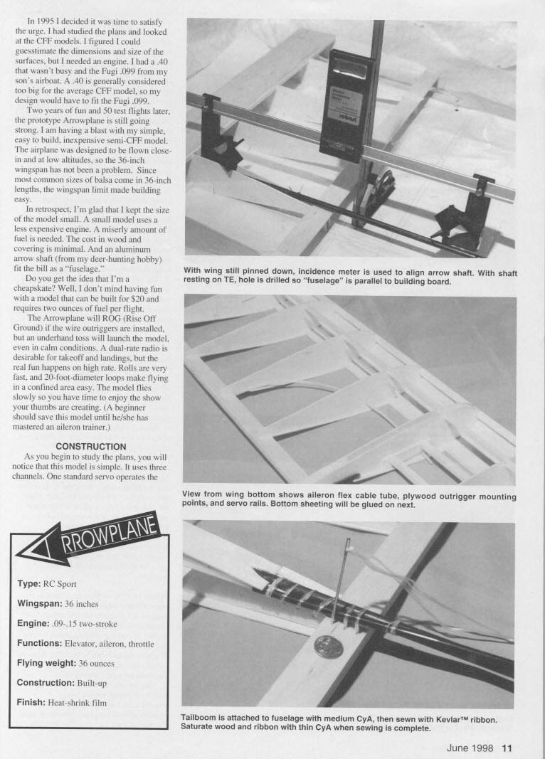
With the wing pinned to the board, use an incidence meter to align the arrow shaft (fuselage). The shaft should be positioned with the trailing‑edge hole drilled and the fuselage parallel to the building board. The wing bottom view on the plans shows the aileron flex cable tube, plywood outrigger mounting points, and servo rails. Bottom sheeting will be glued next.
Final Assembly and Controls
Sew a Kevlar™ ribbon through the hinge areas and saturate the sewing with thin CyA for reinforcement. When sewing is complete, install the ailerons and the hooked elevator.
Install servos: a standard servo for the ailerons, a standard servo for the elevator, and a mini‑servo for the throttle (or a standard servo if you don't need to save weight). Route control cables through the aileron flex tube and secure servo rails as shown on the plans.
The Arrowplane will perform knife‑edge, stall turns, and other maneuvers when properly set up, despite lacking a rudder on the prototype. Add a rudder if you want more axial control.
The model will ROG if you install wire outriggers; otherwise, it will hand‑launch easily. Use dual‑rate for takeoff/landing and high rate for aerobatics.
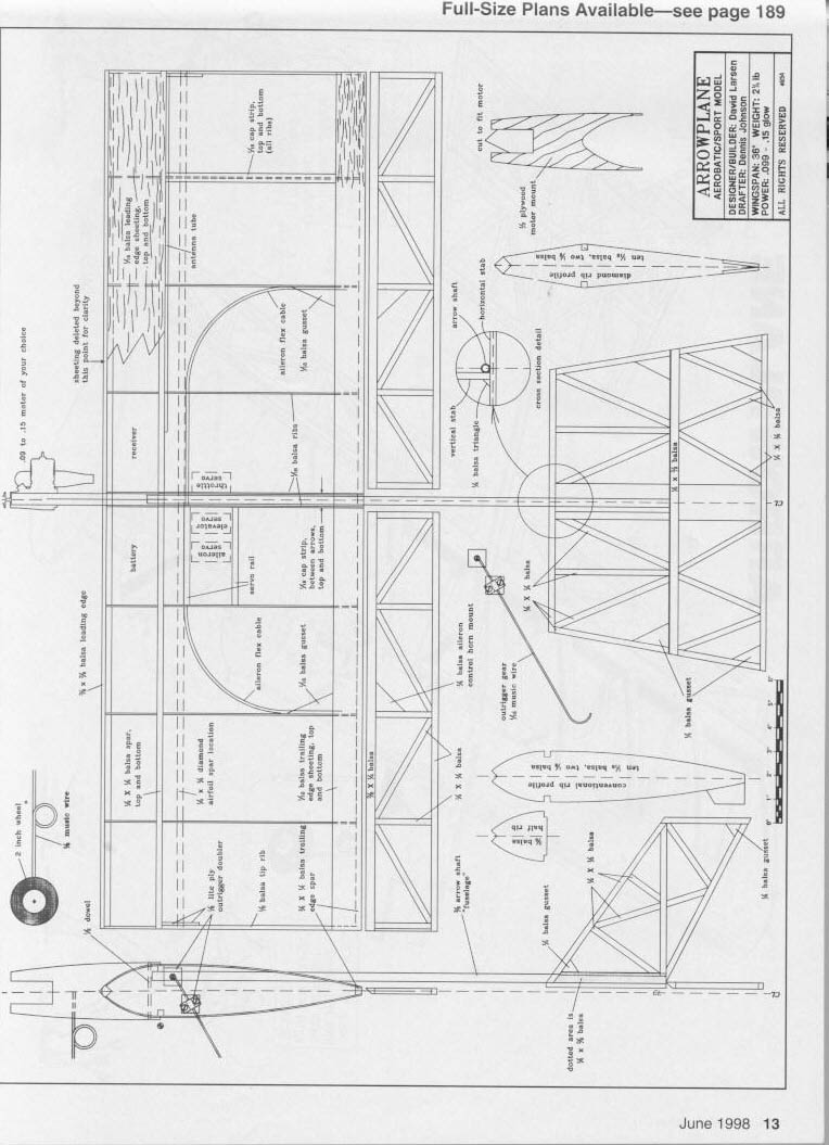
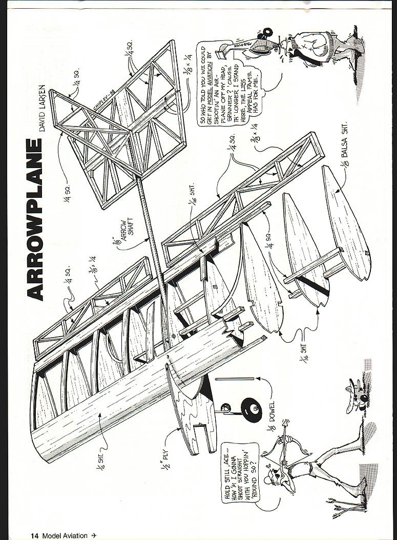
Plans and full‑size drawings are shown on the page.
Transcribed from original scans by AI. Minor OCR errors may remain.

