
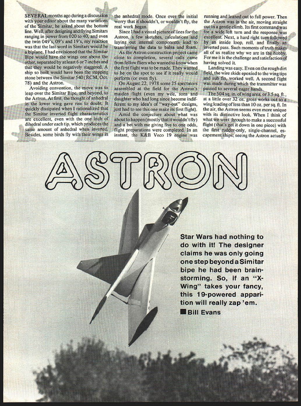
Astron
Several months ago, during a discussion with my editor about the many variations of the Simitar, he asked about the bottom line. After designing and flying Simitars ranging in power from .020 to .40, and even the twin .049's, .09's and .19's, my reaction was that the last word in Simitars would be a biplane. I had envisioned that the Simitar Bipe would have the wings one above the other, separated by at least 6 or 7 inches and negatively staggered. A ship so built would have been the stepping stone between the Simitar 540 (RCM, Oct. 78) and the Astron.
Avoiding convention, I chose to leap over the Simitar Bipe and beyond to the Astron. At first, the thought of anhedral in the lower wing gave me pause. The doubt quickly dissipated when I rationalized that the Simitar’s inverted flight characteristics are excellent, even with one inch of dihedral under each tip (which produces the same amount of anhedral when inverted). Besides, some birds fly with their wings in an anhedral mode. Once past the initial worry that it shouldn't—or wouldn't—fly, the real work began.
With a visual picture of the Astron's lines, a few sketches, calculations and laying out of internal components led to transferring the data to balsa and foam.
As the Astron construction project neared completion, several calls came from fellow fliers wanting to know when the first flight would be made. They wanted to be on the spot to see if it really would perform (or even fly).
On August 22, 1978, some 25 spectators assembled at the field for the Astron's maiden flight (even my wife, sons and daughter—long since somewhat indifferent to my "way-out" designs—had to see this one make its first flight).
Amid conjecture (mostly that it wouldn't fly) and a bet giving five-to-one odds against me, flight preparations were completed. In an instant the K&B Veco .19 engine was running and leaned out to full power. Then the Astron was in the air, moving straight out in a gentle climb. Its first command was a wide left turn and the response was excellent. Next came a hard right turn, an inside loop, a roll, and finally an inverted pass. Such moments of truth make all of us realize why we are in the hobby. For me it is the challenge and satisfaction of having solved it.
Landing was easy. Even on the rough dirt field, the wire skids epoxied to the wing tips and sub-fin worked well. A second flight was made during which the transmitter was passed to several eager hands.
The airplane has 504 sq. in. of wing area (3.5 sq. ft.). At a little over 32 oz. gross, that works out to a wing loading of less than 10 oz. per sq. ft. In the air, the Astron seems even more unique with its distinctive look. When I think of what we went through to make a successful first flight (getting it down in one piece) with the early rudder-only, single-channel, escapement ships, seeing the Astron actually in the air made me feel as if the god of flight had been cheated—and he might surely try to smash this alien craft into the ground. But the Astron is an exciting, perfectly "normal" aerobatic machine.
It doesn't require much balsa. All you need is:
- 4 pieces 3/16" x 4" x 36" balsa
- 1 piece 1/8" x 4" x 36" balsa
- 4 pieces 1/32" x 6" x 36" balsa (sheeting)
- 1 piece 1/4" x 3" x 36" balsa
- 1 piece 1/2" x 36" triangle stock
- 3/16" plywood firewall
Wing foam cores are available for $16.00 plus $2.00 shipping, and 1/64" plywood wing sheeting at $14.00 plus $2.00 shipping from: Soaring Research 19216 Calvert St. Reseda, CA 91335
(Editor's note: You may prefer to order from other sources who also offer custom-cut foam; this reference was given for convenience in case you have no prior experience with sending away for cores.)
Performance and handling
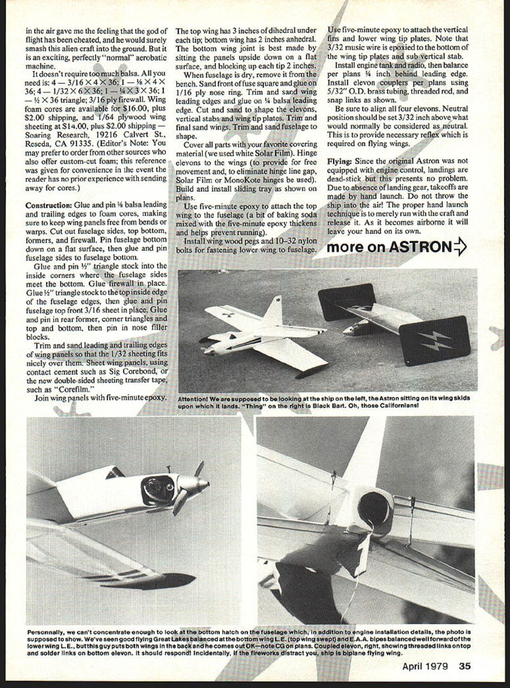
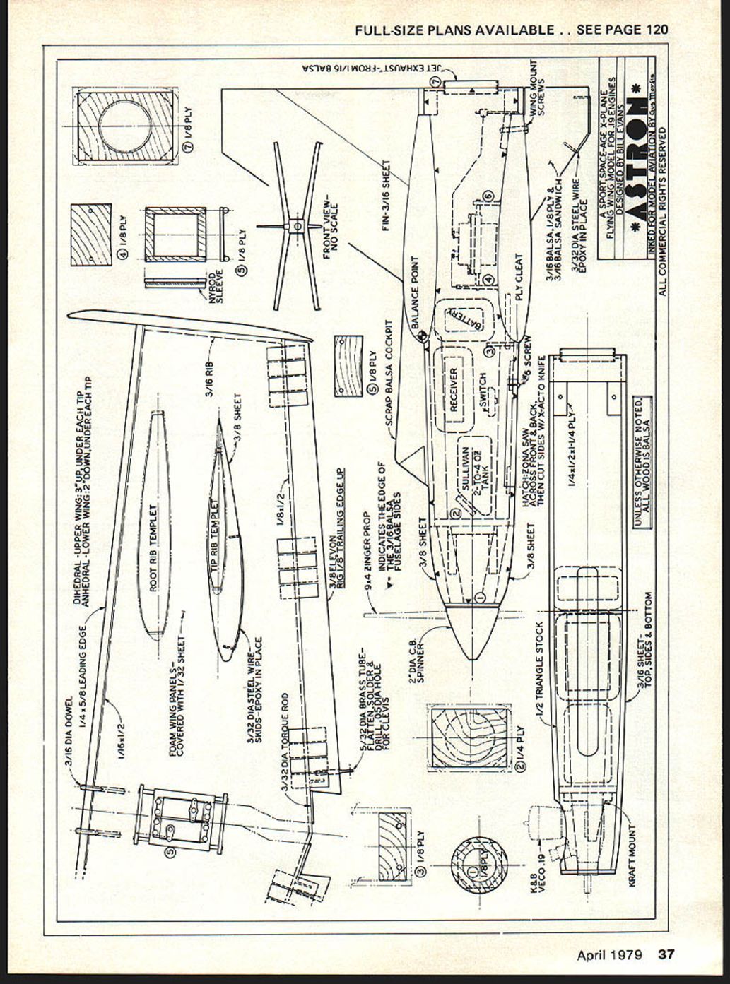
- The top wing has 3" of dihedral under each tip; the bottom wing has 2" anhedral.
- The original Astron had no throttle control, so landings were dead-stick; this presents no problem if you plan for it.
- Takeoffs are by hand launch—do not throw the ship into the air. The proper technique is to run with the craft and release it; it will leave your hand on its own as it becomes airborne.
Captions and notes from flight photos:
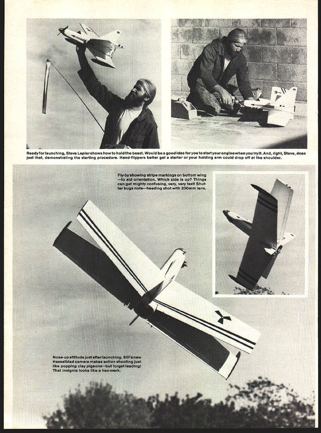
- Ready for launching: Steve Lepler shows how to hold the beast.
- It would be a good idea for you to start your engine when you try it. Hand-flippers better get a starter—or your holding arm could drop off at the shoulder.
- Fly-by showing stripe markings on bottom wing—to aid orientation. Which side is up? Things can get mighty confusing, very, very fast!
- Nose-up attitude just after launching.
Construction
Preparation and sheeting the wings
- Glue and pin 1/4" balsa leading and trailing edges to the foam wing cores, making sure to keep wing panels free from bends or warps.
- Trim and sand the leading and trailing edges of the wing panels so that the 1/32" sheeting fits nicely over them.
- Sheet the wing panels using contact cement such as Sig Corebond, or use double-sided sheeting transfer tape such as "Corefilm."
- Join wing panels with five-minute epoxy.
Notes:
- Use good flat building surface and metal pins to ensure panels remain true.
- The bottom wing joint is best made by placing the panels upside down on the flat surface and blocking each tip up 2".
Fuselage and assembly
- Cut out fuselage sides, top, bottom, formers and firewall.
- Pin the fuselage bottom to a flat surface, then glue and pin the fuselage sides to the bottom.
- Glue 1/2" triangle stock into the inside corners where the fuselage sides meet the bottom.
- Glue the firewall in place.
- Glue 1/2" triangle stock to the top inside edge of the fuselage sides, then glue and pin the fuselage top front 3/16" sheet in place.
- Glue and pin the rear former, corner triangles, top and bottom pieces, then pin in nose filler blocks.
- When the fuselage is dry, remove it from the bench. Sand the front of the fuselage square and glue on a 1/16" plywood nose ring.
- Trim and sand wing leading edges and glue on 1/8" balsa leading edge (as required).
- Cut and sand to shape the elevons, vertical stabs and wing tip plates. Final sand all surfaces.
Attaching wings, fins and tip plates
- Use five-minute epoxy to attach the top wing to the fuselage (mixing a bit of baking soda with the epoxy will thicken it and help prevent running).
- Install wing wood pegs and 10-32 nylon bolts for fastening the lower wing to the fuselage.
- Use five-minute epoxy to attach the vertical fins and lower wing tip plates. Note: 3/32" music wire is epoxied to the bottom of the wing tip plates to form the sub-vertical stab assembly.
Radio, engine and control linkages
- Install engine tank and radio gear; tune the engine.
- Balance per plans at 1/4" behind the leading edge.
- Install elevon couplers per plans using 5/32" O.D. brass tubing, threaded rod, and snap links as shown on the plans.
- Be sure to align all four elevons. Neutral position should be set 3/32" above what would normally be considered neutral. This provides the reflex required on flying wings.
Hinges:
- Hinge elevons to the wings to provide free movement and to eliminate hinge-line gaps. Solar Film or MonoKote hinge strips may be used, or use five-minute hinges as preferred.
Finishing
- Cover all parts with your favorite covering material (we used white Solar Film).
- Trim and final-sand fuselage and wings; shape and dress all edges.
- Build and install the sliding radio tray as shown on the plans.
Flying
- Hand launch technique: run with the craft and release; do not throw. The aircraft will become airborne and leave your hand on its own.
- If the model lacks throttle control, plan dead-stick landings and ensure approach and glide characteristics are safe for landing without power.
- Start the engine prior to launch if possible—this simplifies hand-holding and reduces the risk to the holder.
UNLESS OTHERWISE NOTED, ALL WOOD IS BALSA.
Transcribed from original scans by AI. Minor OCR errors may remain.

