
Atrix
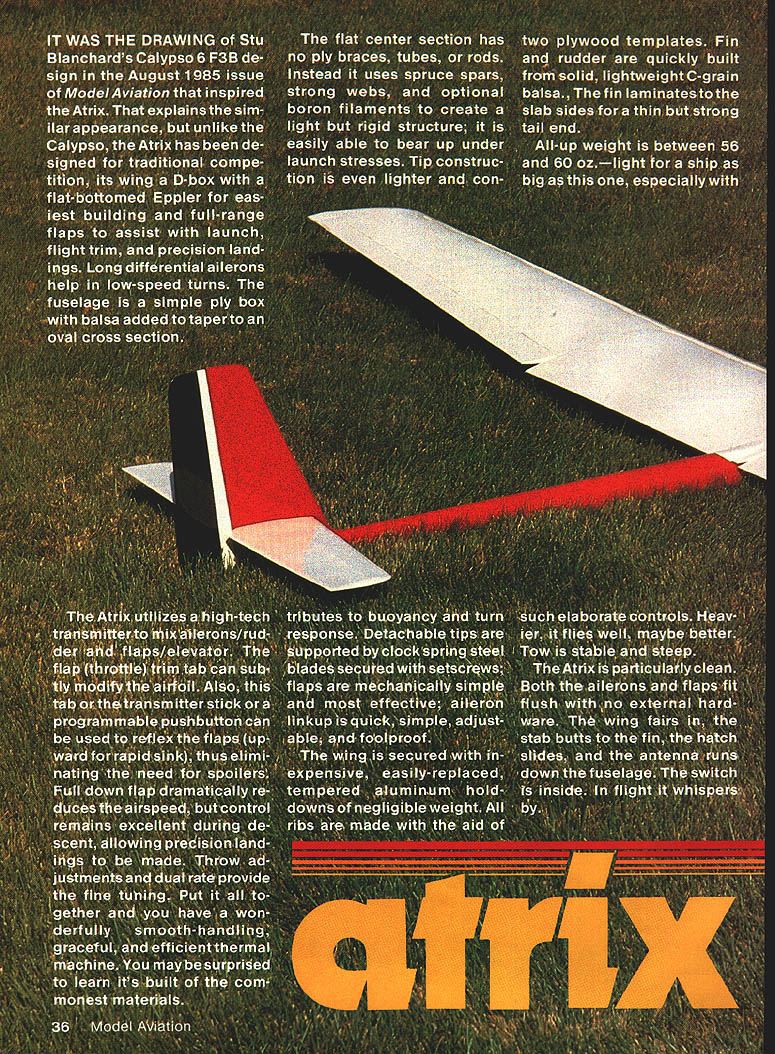
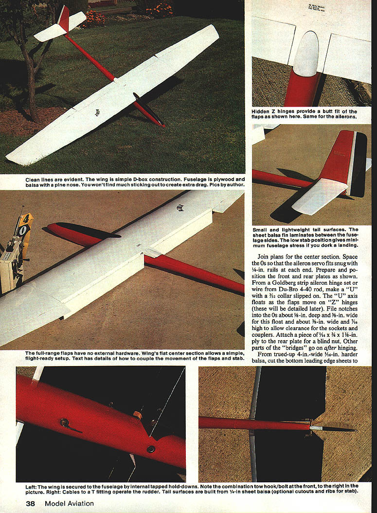
It was the drawing of Stu Blanchard's Calypso 6 F3B design in the August 1985 issue of Model Aviation that inspired the Atrix. That explains the similar appearance, but unlike the Calypso, the Atrix has been designed for traditional competition. Its wing is a D-box with a flat-bottomed Eppler airfoil for easiest building and full-range flaps to assist with launch, flight trim, and precision landings. Long differential ailerons help in low-speed turns. The fuselage is a simple ply box with balsa added to taper to an oval cross section.
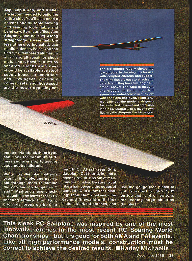
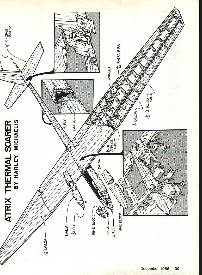
The flat center section has no ply braces, tubes, or rods. Instead it uses spruce spars, strong webs, and optional boron filaments to create a light but rigid structure; it easily bears up under launch stresses. Tip construction is even lighter and contributes to buoyancy and turn response. Detachable tips are supported by clock-spring steel blades secured with setscrews; flaps are mechanically simple and effective. Aileron linkup is quick, simple, adjustable, and foolproof.
The Atrix utilizes a high-tech transmitter to mix ailerons/rudder and flaps/elevator. The flap (throttle) trim tab can subtly modify the airfoil. The tab, a transmitter stick, or a programmable pushbutton can be used to reflex the flaps (upward for rapid sink), eliminating the need for spoilers. Full down flap dramatically reduces airspeed, but control remains excellent during descent, allowing precision landings. Throw adjustments and dual rates provide fine tuning. Put it all together and you have a smooth-handling, graceful, and efficient thermal machine built of common materials.
The wing is secured with inexpensive, easily-replaced tempered aluminum hold-downs of negligible weight. All ribs are made with the aid of two plywood templates. Fin and rudder are quickly built from solid, lightweight C-grain balsa; the fin laminates to the stab sides for a thin but strong tail end.
All-up weight is between 56 and 60 oz.—light for a ship this size, especially with such elaborate controls. Heavier, it flies well, maybe better. Tow is stable and steep. The Atrix is particularly clean: both ailerons and flaps fit flush with no external hardware, the wing fairs in, the stab butts to the fin, the hatch slides, and the antenna runs down the fuselage. The switch is inside. In flight it whispers by.
Recommended adhesives and tools:
- Zap, Zap-a-Gap, and Kicker for general assembly.
- Solvent, table and band saw, Permagrit files, Ace Stix, Jonel nail file.
- Long straightedge, medium-density balsa (unless otherwise indicated).
- 1/16-in. tempered aluminum (have 3/8-in. strips sheared at an aircraft repair or sheet metal shop).
- Clock-spring steel from a steel supply house (or see Materials & Sources).
- Swingees (use newer opposing-set models; handpick for minimum stiffness and arm slop).
Wing
- Lay plan patterns over 1/16-in. ply and push a pin through them to outline the cap and rib templates of T. Mark and shape, checking against the pattern for 1/16-in. sheeting setback.
- From 1/8-in. birch ply, prepare ribs 0 to match C. Attach rear 3-in. doublers.
- Cut four 1/8-in. and a dozen 3/32-in. ribs out of medium-grain balsa. Cut ribs slightly beyond the edges of template C to allow finishing; clamp between the Os and fine-sand until they match.
- Mark for notches and use the gauge (see plans) to cut. Trim ribs through 2, 1/32-in. on top and 1/16-in. on bottom for leading edge sheeting doublers.
- Join plans for the center section. Space the Os so the aileron servo fits snug with 1/4-in. rails at each end. Prepare and position the front and rear plates as shown on the plans.
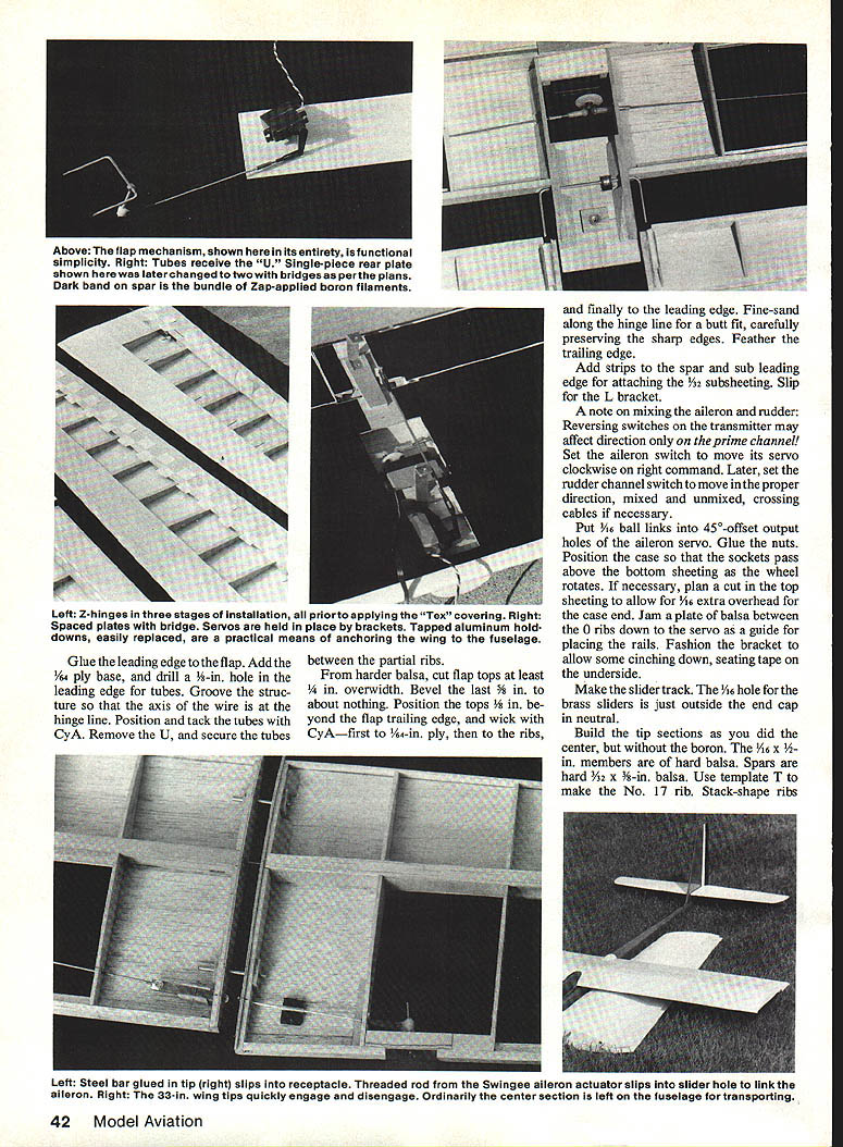
- From a Goldberg strip aileron hinge set or Du-Bro 4-40 rod, make a "U" with a 3/32-in. collar slipped on. The "U" axis floats as the flaps move on "Z" hinges. File notches into the Os about 5/16-in. deep and 3/8-in. wide for this float and about 3/8-in. wide and 7/16-in. high to allow clearance for the sockets and couplers. Attach a piece of 1/16 x 3/4 x 1-1/8-in. ply to the rear plate for a blind nut. Other parts of the "bridges" go on after hinging.
Bottom sheeting and doublers:
- From trued-up 4-in.-wide, 1/16-in. harder balsa, cut bottom leading-edge sheets to fit. Add bottom doublers through ribs to the forward spar.
- Cut flap bottoms and fit 1/32-in. plate outside cap. Mark bevels on the rear of the flaps to about nothing. MonoKote or other covering will use 1/8-in.-wide strips. Over covering backing, wick on 1/32-in.-wide strips of 1/64 ply with Zap and pin in place.
Center section spars and boron filaments (optional):
- Boron filaments add rigidity to the center section but are for careful builders only. A 1,000-ft. spool is available (about 200 ft. used).
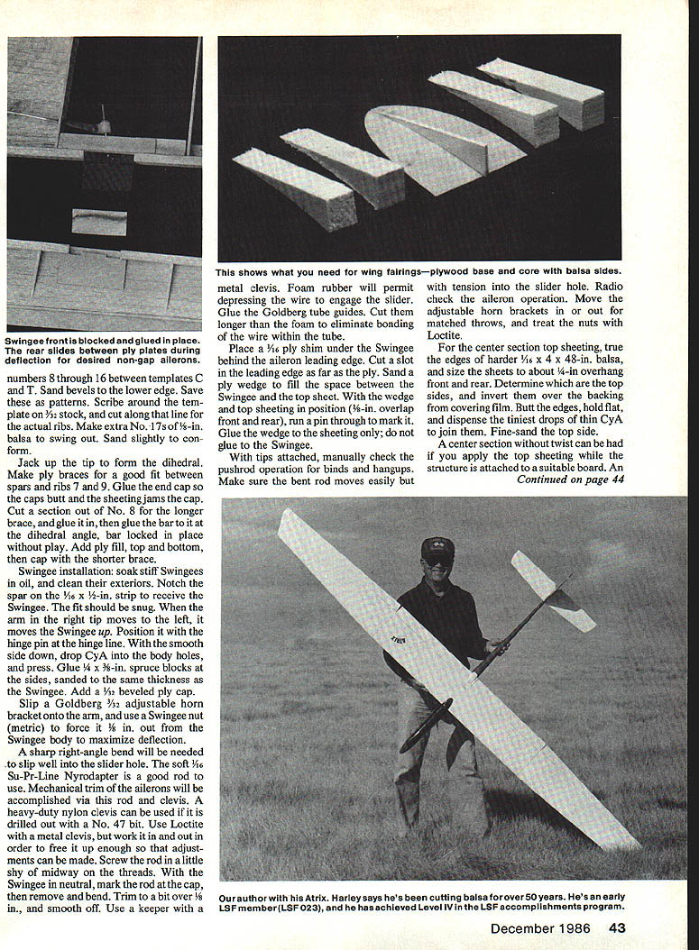
- Make a shallow dispensing box from foam; use a dowel and washer to turn. Dispense filament over a white background. Use eye protection and pliers to break off about 30 pieces 3 ft long. Inspect and pick up tiny shards with masking tape.
- Dangle filaments between thumb and index finger and smooth them flat. Center filaments along the spar line. Use covering-film backing around a finger to hold filaments while applying glue. Tack center and toward the ends with small drops of thin cyanoacrylate (CyA) and set with accelerator. Never run fingers back against broken ends.
- Fit the one-piece bottom spar, apply thick CyA, and hold flat on a board edge until set. Stick pins adjacent to rib cap alignment. Spray ply with CyA accelerator and use slow CyA to position ribs; hold flat until set. Lay cap sets together and drill #6 pilot holes where doublers, tubes and pins are to be added, then drill out as required.
- Cut slots in the steel bar and glue ply ribs over the spar plates. Add the remaining ribs. Use a fine Teflon CyA applicator to ensure no glue extends beyond 1/16 in. on either side of the hinge line.
Center Block Assembly:
- Fit ply pieces between ribs and spars, stack and drill dead center for 6-32 Du-Bro blind nuts. Enlarge the hole in the center piece to accommodate the blind-nut flange. Laminate the assembly with flanges butting, run the bolt through and use fasteners as shown on the plans.
- Glue 1/4-in. solid balsa shear webs where indicated and finish the wing center assembly before final hinging and covering.
Hold-downs:
- Form hold-downs from 1/8 x 3/8-in. tempered aluminum or brass as shown. Avoid overlength and make spares. Glue 3/16 ply plates to the center block assembly as a slot to center and key the hold-down.
- Position the hold-down, L, and top spar on the center block assembly. Through the nuts, drill a 5/64 pilot hole through the center block and top spar.
Rib and spar fitting:
- Fit vertical webs precisely. Do a dry run with the spar and web stock to determine the amount of thick CyA needed. Wick the ribs to the sheeting with CyA. Shape the sub-leading edge.
- Study the steel bar receptacle detail. Solid glue joints are essential. Side members must match the bar height for no play.
Tip attachment and locking:
- Plans show two setscrews in blind nuts for friction hold of the tip. A later locking setup proved advantageous: set a blind nut at the rib 6 locations only, and with a Dremel tool notch the cap about 3/32 in. deep to receive a 1/4-in. setscrew from the wing underside. Trim the bar to slide over the head of the blind nut and lock the bar in place without outward play when gluing into the tips—flush. With this setup the inboard ends of the ailerons need not be angled. Use it top and bottom to center the bar vertically. Make sure the bar slides easily, then cap and fill to the spar edge with balsa. Add the top spar and boron filaments on the bottom.
Aileron construction:
- Section the ribs at the hinge line for the 1/16-in. members. To make beveled and tapered aileron strips, start with a 3-in.-wide sheet, true the edge, cut the bevel, then cut the taper (table saw and band saw are useful). Glue the leading edge to the flap. Add the 1/64-in. ply base, drill a 3/16-in. hole in the leading edge for tubes, and groove the structure so the axis of the wire is at the hinge line. Position and tack the tubes with CyA, remove the U, and secure the tubes between the partial ribs.
- From harder balsa, cut flap tops at least 1/4 in. overwrap. Bevel the last 3/8 in. to about nothing. Position the tops 1/8 in. beyond the flap trailing edge and wick with CyA—first to 1/64-in. ply, then to the ribs, and finally to the leading edge. Fine-sand along the hinge line for a butt fit, carefully preserving sharp edges. Feather the trailing edge.
Subsheeting and L bracket:
- Add strips to the spar and sub-leading edge for attaching 1/32-in. subsheeting. Slip in the L bracket.
Radio and mixing note:
- Reversing switches on the transmitter may affect direction only on the prime channel. Set the aileron switch so its servo moves clockwise on right command. Later set the rudder channel switch to move properly, mixed and unmixed, crossing cables if necessary.
Servo mounting:
- Put 1/16-in. ball links into 45°-offset output holes of the aileron servo. Glue the nuts. Position the case so sockets pass above bottom sheeting as the wheel rotates. If necessary, plan a cut in the top sheeting to allow 1/16-in. extra overhead for the case end. Jam a plate of balsa between the D ribs down to the servo as a guide for placing rails. Fashion the bracket to allow some cinching down, seating tape on the underside.
- Make the slider track. The 1/16-in. hole for the brass sliders is just outside the end cap in neutral.
Sheeting and washout:
- For the center section top sheeting, true the edges of harder 1/16 x 4 x 48-in. balsa and size sheets to about 1/4-in. overhang front and rear. Invert over covering-film backing, butt edges, and dispense tiny drops of thin CyA to join. Fine-sand the top side. Apply top sheeting while the structure is attached to a suitable board to avoid twist.
- Make keying marks across each end at the caps and join to the spar with thick CyA, holding with a surplus board until set. Work toward each tip two or three ribs at a time, wicking overhang to the sub leading edge with instant glue. Trim excess, sand straight, and add the leading edge. Fine-sand to achieve precise mating with the flaps. Keep edges sharp. Inlay the L bracket as required.
- Sheet the tips similarly, building in washout by raising the rear tip with a 1/4-in. beveled strip along the hinge line. Shape the leading edges but don't round them where the hatch butts.
Tip sections, spars, and ribs
- Build tip sections as for the center but without boron. 1/16 x 1/2-in. members and hard 3/32 x 5/8-in. spars are used. Use template T for No. 17 rib and stack-shape ribs 8 through 16 between templates C and T. Scribe around templates on 3/32 stock and cut actual ribs; make extra No. 17s of 1/8-in. balsa to swing out and sand to conform.
- Jack up the tip to form the dihedral. Make ply braces for a good fit between spars and ribs 7 and 9. Glue the end cap so caps butt and sheeting jams the cap. Cut a section out of No. 8 for the longer brace, glue it in, then glue the bar to it at the dihedral angle; gear should lock without play. Add ply fill top and bottom, then cap with the shorter brace.
Swingee installation
- Soak stiff Swingees in oil and clean their exteriors. Notch the spar on the 1/16 x 1/8-in. strip to receive the Swingee; fit should be snug. When the arm in the right tip moves left, it moves the Swingee up. Position with the hinge pin at the hinge line; with the smooth side down, drop CyA into the body holes and press.
- Glue 1/4 x 3/8-in. spruce blocks at the sides, sanded to the same thickness as the Swingee. Add a 1/2-in. beveled ply cap. Slip a Goldberg 3/32 adjustable horn bracket onto the arm and use a Swingee nut (metric) to force it 1/16 in. out from the Swingee body to maximize deflection.
- Use a soft 1/16 Su-Pr-Line Nyrodapter or similar rod. Mechanical trim of the ailerons will be via this rod and clevis. A heavy-duty nylon clevis can be used if drilled out with a No. 47 bit. Use Loctite with a metal clevis but work it in and out to free it for adjustment.
- Screw the rod in slightly shy of midway on the threads. With the Swingee neutral, mark the rod at the cap, remove and bend, trim to a bit over 4 in., and smooth. Use a keeper with a metal clevis.
- Foam rubber will permit depressing the wire to engage the slider. Glue Goldberg tube guides, cut longer than the foam to avoid bonding the wire within the tube.
- Place a 1/16 ply shim under the Swingee behind the aileron leading edge. Cut a slot in the leading edge as far as the ply. Sand a ply wedge to fill space between Swingee and top sheet. With wedge and top sheeting in position (1/8-in. overlap front and rear), run a pin through to mark it. Glue the wedge to the sheeting only; do not glue to the Swingee.
- With tips attached, manually check pushrod operation for binds. Radio check aileron operation, adjust horn brackets for matched throws, and treat nuts with Loctite.
Flap/elevator mixing and servos
- Flap/elevator mixing: elevator pushrod moves forward to impart down when flaps move down. To achieve correct mixed and unmixed directions, reverse servo directions with switches or flop the servo to the opposite side.
- Use a squat flap servo such as Airtronics 94461 (leads 1, 2, 3 = signal, negative, positive). The long Futaba FSH-6E arm fits the 94461 shaft. Block around the case so it can't move. With stick at extreme throw and trim tab centered, angle the arm about 45° rearward and secure with a bracket.
- For starters, adjust mixer so flap down produces about 1/8 in. of up motion at the stab; fine-tune from there.
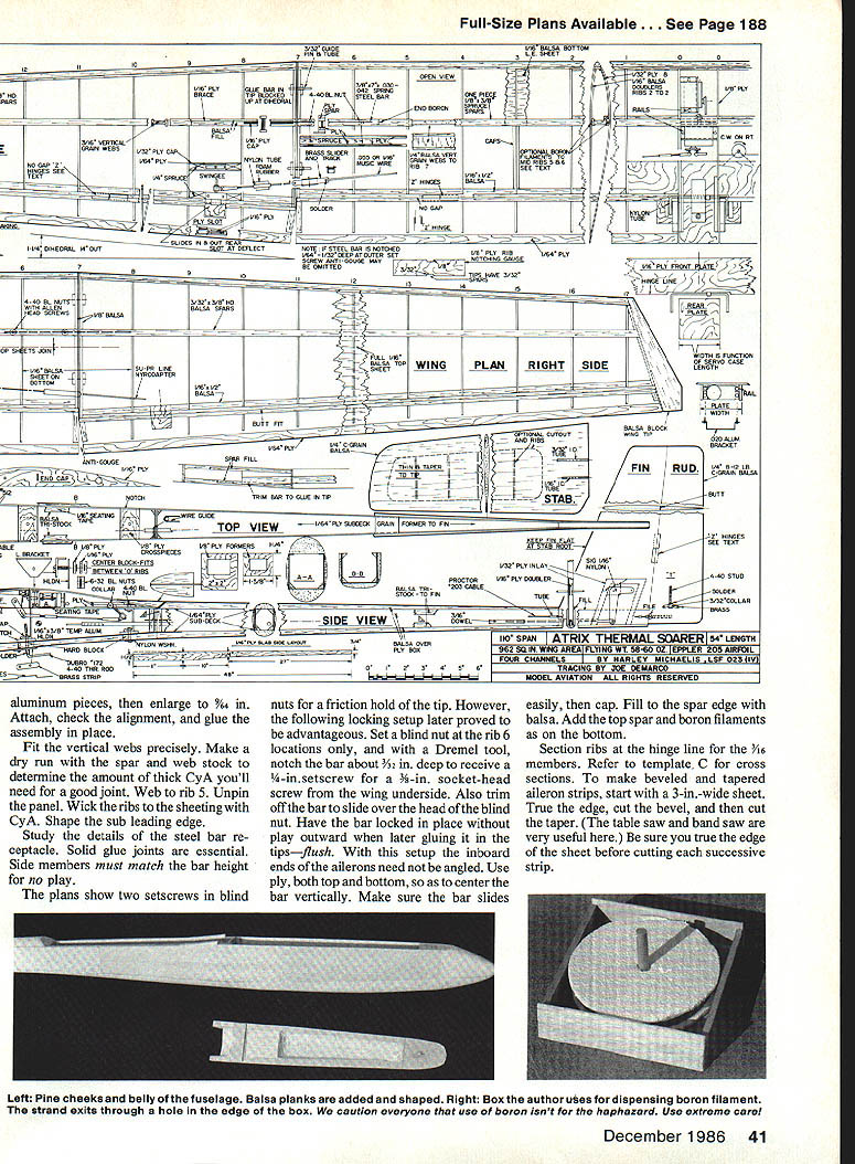
Fuselage
- A table saw and band saw speed construction. Rip a pair of 2 1/4-in.-wide pieces and position them to oppose any twist. Hold together with thumbtacks or spot glue and align along the top behind the front former. Sand to a fine finish, mark one side, and cut both to profile with the band saw. Notch for 1/8-in. ply crosspieces and sand edges true.
- Make formers. Add a block to the former to attach the servo. Glue triangular stock to the front former (rudder servo can also go behind the former). Join front former at right angles in an L-shaped jig to get fronts even. Add triangular stock to the rear former, bevel edges, and glue it on.
- Prepare the nose core. Angle edges like the sides. The keyhole plate recesses on it. Fit spacer blocks and cap the rear with 3/32 ply. Trim where the hatch screw passes. Prepare the keyhole plate without the keyhole.
- Add hard triangular stock between formers and forward on the bottom to the servo blocks. Clamp in the nose core. On 1/32 ply draw a centerline for the bottom. Position the fuselage on it and mark an outline along its exterior. Fit and glue crosspieces. Invert onto the work surface when gluing in the core assembly, and shim with the keyhole plate so it is on plane with the top edge of the sides. Glue on the ply bottom.
Planking, hatch, and ballast:
- Using the band saw, cut exterior planking for shaping using hard blocking up front and by the hold-downs. Attach with slow CyA and accelerator. Feather to the box except by the saddle center.
- When ready for fine sanding, position the hatch block at the wing leading edge point, mark perimeter and profile, cut with a band saw, and add 1/64-in. ply along edges. Excess at the front of the 2-in. block can be glued to the rear over the ply edge for extra width and length. Attach rear key.
- Drill a 1/16-in. hole in a length of 1/4-in. dowel, center it in the block where the screw goes, drill through to locate the keyhole slot rear, and shape the keyhole. Shape the hatch and groove the underside so cables can pass over the former. Add contoured area aft of the saddle. Optional skid can be set in a slot during construction or Goldberg wing skids can go in after covering. Drill shallow holes for rudder cable tubes; insert and trim flush.
- Attach hold-downs temporarily, then make a template from scrap 1/8-in. ply with holes spaced to match the hold-down tabs. Place into position on interior bottom and mark for drilling. Make slots about 1/4 in. long to more easily locate tabs through the fuselage underside.
- Glue 1/16-in. sheet lead cheeks (plumbing supply) to the nose core; this adds about 3 oz. to balance with an 800–900 mAh battery pack.
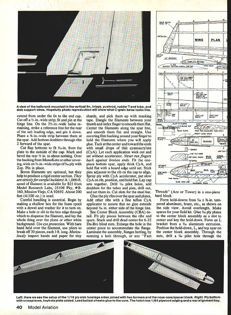
Fin, tail surfaces, bellcrank, and linkages
- Cut the fin to profile and make inlays and cutouts to match. Center 3/8 x 1/4-in. strips inside. Slot the fin bottom.
- For hole sizes and clevis pins: use a No. 40 bit for 3/32-in. wire, No. 51 or 52 bit for metal clevis pin on the bellcrank, and No. 54 for 1/16-in. wire.
- Add inlay doublers; glue one inlay, position the bellcrank inside and drill a 1/16-in. pilot hole at the pivot point, then attach the other inlay with a 1/16-in. shim between. Drill a hole with a sharp 3/32-in. bit, mark, cut and smooth 1/16-in. wire arcs, and insert the bellcrank with clevis and Goldberg true 1/16-in. threaded rod attached.
- Make main 1/2-in. support and run through. Widen slot so clevis doesn't bind. If bellcrank binds, pry between the doublers and zap the wire in. A dowel-end drill guide may be made from 2 in. of 1/16-in. I.D. brass tubing shimmed to 1/16 in., with 1-in. bits of telescoping tubes.
- Add triangular stock where the fin extends for the 1/4-in. ply subdeck. With the pushrod through the formers, glue the fin to the right side of the stab flush with the bottom and 1/8 in. from the end. Clamp between the other side and align using a string from nose pin to fin for no built-in turn. Sand sides precisely to the fin rear to establish position, then slow-glue and re-clamp.
- Bring the fin upright by twisting the fuselage between your knees as progressive 1-in. lengths of subdeck are added from the fin forward, top and bottom, with slow CyA. Protect fingers with backing and sand edges in plane with sides.
- Glue in the keyhole plate.
Stab and stab servo:
- Cut stabilizer halves to planform and butt to the fin to locate tubes. Cut slots to be faced with 1/4-ply and fit a 1/4-in. strip of 1/8-ply between facings flush with the stab bottom. Lay in a 5/8-in. O.D. tube, tack with CyA, slip off, then secure with CyA, epoxy putty, and a strip of 1/8-in. ply on top. Repeat for the other tube. Optionally remove centers and notch balsa strips for ribs. Shape to a symmetrical section thinning toward tips.
- The stab servo goes under a bracket with output arm pointing up and pushrod to one side. At the rear former, add a guide around the pushrod to reduce bending under load. Cables can be run down the finished fuselage from the rear end; at the servo end, knots secure a Sullivan 2-56 threaded coupler. Use metal clevises and crimp cables into a T with bits of tubing.
Hidden Z hinges for flaps and ailerons
- Install hidden Z hinges after the wing has been sanded, vacuumed, tacked, and is ready for covering. These hinges are made from MonoKote and provide close fits; they can also compensate for any bow in the leading edge.
- Procedure:
- Cut strips of MonoKote around 1 in. wide to face the hinge and adjacent structure. Use a 1/16-in. metal bar to trim to overlap on both top and bottom.
- Apply separate pieces of covering around the ends and adjacent wing portions. Trim to 1/8 in.
- Cut four 1/4-in.-wide strips a bit longer than the flap. Lay one adhesive-side up by a straightedge and mark a reference line slightly less than the thickness of the flap leading edge. Tack the top strip at the line, then seal at a table edge.
- Cut into 1-in. hinges. Slip in the U, tape the flap to the wing, insert, center, and progressively iron hinges to the upper surface in a checkerboard pattern from the U toward the tip. With surfaces butted and aligned, pull on the hinges to remove slack and progressively iron to the bottom. Trim to 1/8 in.
- Slip in the U and tape the flap to the wing. Manually activate flaps to ensure everything floats freely. Add remaining brackets.
Flap linkage and trim tab:
- Slide the collar onto the U for a straight shot to the output arm. Attach stud with a nylon bracket hole 3/4 in. from the U axis. Bend the soft-wire U so flaps are in a plane with each other. Temporarily tighten the stud in the collar, set the screw hole at 45° or more rearward. Groove the rear plate to permit up-flap. Fit the link to the output arm. With the trim tab neutral, attach links, bracket on stud, and adjust angles of stud, output arm, and servo throw to get near 90° down. Use minimum adjustments. Solder collar and stud in place.
- If you have a programmable pushbutton for the flap, adjust for about 1/2 in. of up.
Covering
- Cover wing and flaps simultaneously. You may use one piece, but two-piece covering allows different bottom color and is simpler.
- Cut a 1-1/2-in.-wide piece to fit over the top with about 3/8-in. overlap around both leading and trailing edges. Attach the aluminum portion of the hold-down. With wing inverted, tack covering to center section and proceed with shrinking and finishing.
- Cover along the leading-edge break but don't iron down the overlap. Turn wing right side up. If tack looks straight, iron along the break and toward the inboard flap ends, then slit the covering there.
- Drop the flap to make a 1/16- to 3/16-in. space along the hinge line. Pull covering around flap trailing edge, tack, and iron to the trailing edge underside, working out wrinkles. Tack at end caps, then progressively slit, pull around cap, and overlap on bottom. Use heat gun to remove slack and iron covering to hinges. Center a straightedge along the gap and slit, trim excess carefully. Slip bottom covering under top, tack, then iron down overlap. Repeat for the bottom and trim at cap edge. Puncture at setscrew location. Protect hinge line seal with cardboard while final shrinking with heat gun. Push U wire well into tubes and secure with Zap.
- Install hold-downs with a 1/2-in. hex-head tempered bolt at the front and a 3/8-in. one at the rear.
Tips and ailerons covering:
- Attach facing strips and trim to 1/16 in. as for flaps. Hinge strips should be joined on a taper. Make four hinges from root to Swingee and number progressively at 1-in. spacing. The gap narrows toward the tip—slit with care.
Setting up, balancing, and initial flights
- Balance about 3-1/2 in. rearward of the leading edge.
- Set the stab so there is about 3/4° of throw each way at the leading edge. Align stab trailing edge with the fuselage top in neutral (slight positive incidence).
- Ensure washout is equal and at least 1/4 in.; the ship will not stabilize in a flat, level glide without it.
- Set inboard aileron throw at least 1/2 in. with no reflex up in neutral. Very little down (1/8 in. or less) is needed—too much causes adverse yaw and tip walk. Avoid excess servo rotation which can reverse down aileron. Set any coupled rudder for 1/2 in. maximum deflection.
- For starters, adjust mixer for about 1/8 in. of motion up at the stab as flaps go from neutral to full down.
Initial flight checklist and recommendations:
- Go easy tightening the hold-down bolts.
- Hand test-glide with flaps neutral and adjust stab linkage for a level glide.
- Tow first without flaps. After release, let the ship build speed and flatten out. Give down trim to keep it boring ahead. To cruise slowly, trim in a little down flap rather than holding the nose up.
- Practice turns and get familiar with handling. Hold in a 15°–20° dive and release controls. If it balloons, move balance farther rearward and retrim elevator. If it tucks, add lead and up-trim. Aim for gentle automatic pullout if preferred. Check low rates.
- Check flap/elevator mixing only at safe altitudes. Ease in and out of flap slowly—full down rapidly can stall even with correct mixing. Fine-tune mixing so full down yields the desired descent path. Use pushbutton to neutralize flaps before ground contact; use as spoilers if needed.
Operational notes:
- When mixing is right, 1/4 to 3/8 in. down flap dramatically steepens the tow. Up elevator can be applied when airspeed is adequate. Neutralize flaps just before release. Use pushbutton for brief up-flap to increase zoom speed.
- Set any coupled rudder or aileron/rudder mixes carefully; reversing switches may only affect the prime channel—check directions on both channels.
Materials and sources
- Common materials: medium-density balsa, C-grain balsa for fin/rudder, spruce spars, birch ply for ribs, tempered aluminum for hold-downs, MonoKote or equivalent covering film.
- Boron filament spool: Model Research Labs (example source listed previously).
- Clock-spring steel: available at a steel supply house. If you cannot find clock-spring steel, send $1.00 with a pre-addressed heavier envelope and 39¢ postage to:
Harley Michaelis 26 S. Roosevelt Walla Walla, WA 99362
Note: Construction must be correct to achieve desired performance. Follow the plans and details (templates, Center Block Assembly, and cross sections) meticulously. ■ Harley Michaelis
Transcribed from original scans by AI. Minor OCR errors may remain.

