
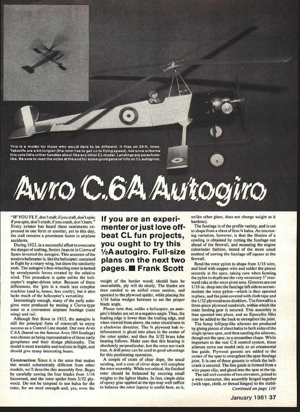
Avro C.6A Autogiro
If you are an experimenter or just love off‑beat control‑line (CL) fun projects, you ought to try this 1/2A autogiro. Full‑size plans appear on the following pages. — Frank Scott
Introduction
"IF YOU FLY, don't stall; if you stall, don't spin; if you spin, don't crash; if you crash, don't burn." Every aviator has heard these sentiments, yet stall remains a prominent factor in airplane accidents. In 1923 Señor Juan de la Cierva of Spain invented the autogiro to overcome the danger of stalling. This ancestor of the modern helicopter is sustained in flight by a rotary wing, but unlike a helicopter its rotor free‑wheels, being turned by aerodynamic forces from the relative wind rather than engine power. That makes the autogiro mechanically simpler and less costly, though less versatile than the helicopter.
Many early autogiros were produced by mating a Cierva‑type rotor to a convenient airplane fuselage (sans wing) and tail. The Avro C.6A model presented here is based on the famous Avro 504 fuselage. It is tractable and realistic in flight and should provide many interesting hours.
Construction — general notes
Since the rotor makes this model substantially different from other CL models, the rotor assembly is described first. Unless otherwise noted, measurements use inch conventions (e.g., 1/16‑in.). Use epoxy where indicated for strength and dimensional stability.
Rotor
- Saw four blades from 1/16‑in. basswood and make the rotor spider from 3/32‑in. plywood. Do not use balsa for the rotor spider; if basswood is not available, ply will do nicely.
- Sand the blades to an airfoil cross section.
- Epoxy the blades to the plywood spider, placing 1/16‑in. balsa wedges between blades to set the proper blade angle.
- Note: unlike a helicopter, an autogiro's blades are set at a negative angle (leading edge lower than trailing edge). When viewed from above the rotor should turn clockwise.
- Glue a 1/8‑in. plywood hub reinforcement into the center of the rotor spider and install a 3/32‑in. brass tube bearing. Ensure the bearing is absolutely perpendicular (a drill press aids accurate positioning).
- Apply a couple coats of clear dope, sand, and finish with silver dope.
- Balance the finished rotor by adding small weights to the lighter blades. Simple dabs of epoxy at the tips often suffice (epoxy does not change weight as it cures).
Fuselage and firewall
- Cut the profile fuselage from firm 1/4‑in. balsa.
- A variation to simulate a cowling: cut the fuselage out ahead of the firewall and mount the engine sidewinder fashion rather than sawing the fuselage square at the firewall.
- The firewall is a three‑piece plywood sandwich; the main landing gear is secured within it. Epoxy this assembly into place and add an Epoxylite fillet to strengthen the joint if desired.
- Cut 1/16‑in. deep grooves in the fuselage left side to accommodate the rotor pylon; epoxy the pylon into place and cover the joint with cloth tape and 1/32‑in. plywood nose doublers.
Rotor pylon and landing gear
- Bend the rotor pylon from 1/16‑in. music wire. Bind with fine copper wire and solder securely at the apex.
- Form the pylon with a 5° rearward rake at the rotor pivot area.
- The optional center skid is formed and secured to the fuselage with epoxy and cloth tape, then bound with fine copper wire and soldered to the spreader bar, which is likewise wire‑bound and soldered to the landing gear.
Ailerons, bellcrank and line guide
- The lollipop‑style ailerons are made by gluing sheet balsa to both sides of a single spruce spar and sanding to a streamlined shape. On the full‑scale C.6 these are part of the control system; on the model they act mainly as an ornamental line guide.
- Add plywood gussets at the center of the spar to strengthen the spar‑fuselage joint. One of these gussets carries the bellcrank (use Goldberg nylon 1/4 A bellcrank and horn set).
- Form the line guide from a wire paper clip or similar wire and glue into the spar tip.
Tail unit
- The tail consists of two elevators joined by a wire connector. Hinge the elevators together with tape, cloth, or thread hinges and glue the assembly into its slot in the fuselage.
- Glue the rudder to the fuselage carefully (small gluing area). Offset the rudder 1/4‑in. to the right, as is common on most CL models.
Finishing and engine installation
- Apply a couple coats of filler (clear dope mixed with talcum powder), sand smooth, and finish with silver dope.
- Paint the nose black and apply RAF decals where appropriate.
- Screw the Cox .049 Babe‑Bee engine into place and fit the propeller.
- Secure the wheel retainer to the rotor mast by sliding it on as far as it will go, add a washer, and secure with another washer and wheel retainer.
- If the rotor bearing is too snug, loosen it by applying a drop of oil mixed with a dab of toothpaste and turning the rotor by hand.
- Install the control system and wheels.
Preflight balance and lubrication
- Aim for the model to balance approximately 5/8‑in. ahead of the rotor pivot (see "Notes" below). Before flying, verify balance and place a drop of oil on the rotor bearing and wheels.
Flying
- Select a smooth, open flying site that allows a full circle.
- The four‑bladed rotor will spin up on its own; hand‑spinning the rotor is not recommended.
- The autogiro requires a somewhat lengthy takeoff run to bring the rotor up to flying speed. The Avro's long tail provides a convenient handle for your helper during starting and gives good longitudinal stability.
- For flying lines use .008‑in. diameter x 35‑ft. wire lines for greater strength and lower drag compared to Dacron.
- Once airborne, the giro flies much like other CL models until the engine stops. When the engine quits, the model will descend nearly vertically and slowly in a flat attitude (a parachute‑like descent) regardless of control inputs. This is due to rotor drag, lack of propwash on the tail, and the fact that the rotor cannot stall like a wing.
- Because the ship has little "reserve" airspeed, fly preferably on windless days; in a breeze consider flying a kite instead.
Avro C.6A Materials List
- 1/4 x 2‑in. sheet balsa
- 1/4 x 1‑in. sheet balsa
- 3/32 x 3‑in. sheet balsa
- 1/16 x 3/16‑in. spruce
- 1/16‑in. plywood
- 1/32‑in. plywood
- 1/16‑in. basswood
- 1/16‑in. diameter music wire
- .045‑in. diameter music wire
- 3/32‑in. outside diameter brass tube
- Fine copper wire
- Goldberg nylon 1/4 A bellcrank and horn set
- Williams Brothers 1‑1/4‑in. diameter WWI wheels
- Small washers
- 1/16‑in. wheel retainers (4)
- Paper clip
- Cox .049 Babe‑Bee engine, propeller, and mounting screws
- Titebond and epoxy glue
- Solder
- 3/4‑in. wide nylon tape
- Fuelproof dope: clear, aluminum and black
- RAF decals
A Few Notes Concerning the Design, Building and Care of Small CL Autogiros
These observations come from an empirical series of generally successful 1/2A CL autogiros and should be useful to fellow modelers of unorthodox aircraft. Keep in mind that CL leadouts and flying lines act as stabilizers in both yaw (vertical) and roll (longitudinal) axes; rotorcraft often have roll stability challenges, so some observations here are specific to CL rotorcraft.
- Rotor diameter and flying speed
- Flying speed is, to an extent, inversely proportional to rotor diameter and total blade area. Large‑diameter rotors yield lower airspeeds, making models susceptible to wind and gusts. They can exhibit uncontrollable pitch‑up when the engine stops (followed by a parachute descent), may be radially floppy (causing control difficulties), and can flex downwards on hard landings enough to strike the fuselage or tail.
- Small rotors
- Small rotors require a longer takeoff run to attain flying RPM, will spin faster, and provide more effective control, producing a more airplane‑like flight.
- Number of blades
- Two‑blade rotors are easiest to build and to handle when starting. Multi‑blade rotors spin up faster (shorter takeoffs) and support heavier aircraft. A three‑blade rotor is often the best compromise between handling and performance.
- Rotor tilt (disc incidence)
- Tilting the rotor disc rearward is common; if the pivot is left vertical the model will fly nose‑high and require an excessive takeoff roll.
- Center of gravity (CG)
- Aim for the CG about 5/8‑in. ahead of the pivot for good control. (Builders have used slightly different values in practice; verify balance carefully before flight.)
- Wings
- Early full‑scale autogiros used wings, but on models wings can be problematic: a wing might lift the aircraft before the rotor attains flying RPM, then as rotor drag increases the model can slow and the wing stall. It's better to rely entirely on the rotor; if wings are fitted, make them too small to support the model in normal flight.
- STOL (Short takeoff and landing) operations
- Properly constructed autogiros can land in very small spaces, but short takeoffs are unlikely without a rotor spin‑up mechanism driven from the engine (shafts/clutches), which adds complexity.
- Control surfaces and tail moment
- Conventional airplane‑type tail surfaces work well and provide airplane‑like control. A long tail moment arm is desirable for elevator authority and for convenient handling and launching.
- Lift and weight
- The Avro C.6 built as described weighs about 6 oz.; variants with two blades may weigh around 9 oz. The model remains manageable in up to a 10‑mph breeze if properly built.
Care and transport
- Make the rotor readily removable for easier transport.
- Lubricate the rotor pivot and inspect the rotor for security and damage between flights.
Transcribed from original scans by AI. Minor OCR errors may remain.

