
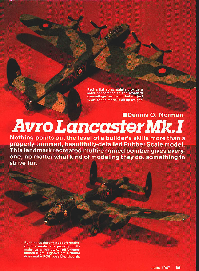
Avro Lancaster Mk.I
Dennis O. Norman
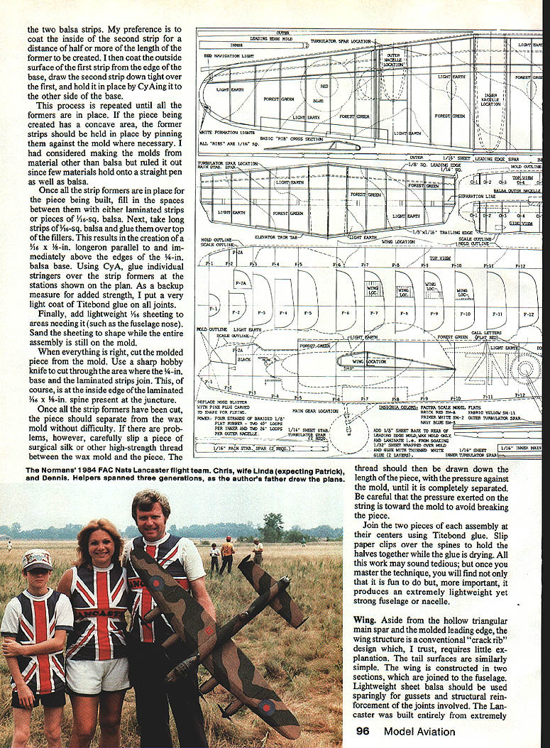
Nothing points out the level of a builder's skills more than a properly trimmed, beautifully detailed rubber-scale model. This landmark recreated multi-engined bomber gives everyone, no matter what kind of modeling they do, something to strive for.
The creation of a nice-flying four-engine rubber-powered model has intrigued me for several years. Once I tried it, the unusual and even unique problems I encountered along the way required some pretty unconventional solutions.
In 1980 I built a 60-in. span version of the Tupolev Tu-20 "Bear." It enjoyed only minimal success before being smashed to pieces at the 1982 Flying Aces Nationals. The lessons learned from the Bear were applied to the Lancaster with vastly better results. The Lanc has completed numerous successful flights with its best-flight time of 45 seconds. Its potential is still being developed, and I believe that flights of one minute or more are attainable.
This model is unique. Frankly, once you understand what is involved, you may not want to build it. I do hope, though, that the design ideas incorporated in it will be of use to those who wish to build lighter, better-performing rubber-powered scale models.
Design philosophy
The model Lancaster as I have built it has no conventional ribs or formers. Instead, it is built almost entirely of strip wood using what is known as the cracked-rib technique for the flying surfaces and what I have coined the "strip-former" technique for the fuselage and nacelles.
The full-scale Lancasters were famous for their strength and load-carrying capacity. The key to their strength was a combination of a strong full-depth main spar in the wing together with a sturdy fuselage backbone. The model incorporates a similar philosophy: it is built around a strong hollow triangular spar in the wing mated to a torsion box that runs the length of the fuselage.
The wing leading edge was molded over a waxed form. The "ribs" are built up from strong 1/16-in. square balsa strip. The wing tips are laminated strip balsa formed around waxed patterns cut to the size of the inside curve.
My original Bear was destroyed in a low-altitude roll, which vividly demonstrated the leverage force of a wing-tip impact on the wing root and fuselage. To avoid this sort of massive destruction in the Lancaster, the wing tips were designed to detach at a point just outboard of the outer nacelles using a tongue-and-box arrangement. Sheet balsa is used only in those areas requiring additional strength, such as the spars and major attachment points.
Weight reduction is one of the key ingredients of successful rubber-powered models. The Lanc, as built, is very light for its size and yet has the necessary strength where it counts.
Fuselage and nacelles — strip-former construction
Originally I got the idea of constructing the Lancaster fuselage and nacelles from a ship-modeling magazine article on making wooden boats by assembling over waxed male molds. Carved undersize to allow for whatever thickness the finished shell would be, the Lancaster fuselage and nacelles, at 1/16-in. thickness, consist of a 1/16-in. square strip former made by laminating either two pieces of 1/32 x 1/16 strip balsa with white glue or laminating four pieces of 1/64 x 1/16 strip balsa over a waxed-balsa mold. Formers and 1/8-in. square stringers are added to complete the shell. The fuselage is built in two halves separated on its mold and joined together; the center nacelle is built the same manner.
The Lancaster required carving 22 molds, 58 vacuum-formed plastic parts and seven laminated wooden parts.
Carving molds seems a forbidding chore but need not be so. The Lancaster plan shows molds drawn differently than the model-airplane plan you may have seen before: the scale lines for the fuselage nacelles are represented by dotted lines and the crucial shape of the molds by solid lines.
I developed a faster approach to carving the fuselage-nacelle molds which I call the "sliced‑bread" system. It avoids the tedious process of making a full solid model and checking many cross sections.
Carving molds — the sliced‑bread system
- Prepare a profile base
- Trace the solid outline of one-half of the fuselage or nacelle onto a piece of hard, flat 1/4-in. balsa sheeting.
- Cut out the traced shape with a bandsaw or similar tool, ensuring a 90° cut.
- Draw the station lines on the 1/4-in. sheet profile corresponding to the vertical formers shown on the plan's side view. Set the profile aside — it will serve as the base for the mold.
- Prepare cross-section patterns
- Trace the cross-sectional formers from the plan onto tracing paper.
- Transfer the tracings to brightly colored heavy-stock paper (I prefer blue). The colored paper will help during carving.
- Build and slice the balsa block
- Select straight-grained balsa block at least as wide as the side view of the piece and at least half of the top view.
- Glue blocks together (butt-glue with white glue) to get the required thickness. Sight along the block to ensure it is straight; plane and sand true.
- Draw the station lines on the edge of the block corresponding to the profile.
- Glue the 1/4-in. profile to the edge of the block.
- Using a bandsaw or a very sharp knife, slice off pieces of the block at the station lines. Keep the slices in order.
- Assemble the sliced loaf
- Glue each slice to the profile, aligning with the station lines.
- When dry, sand the assembly to match both the profile and the colored cross-section patterns. Fill gaps with balsa filler and finish-sand smooth.
- Wax and lay up the shell
- Wax the completed mold with a thin coat of paraffin (melted in a double boiler). Brush on one quick coat; avoid repeated heavy coatings.
- Smooth the wax with a whittling blade working perpendicular to the surface.
- Laminate 1/64 x 1/16 strips over the waxed mold and formers.
- After removing the shell, add 1/16-in. square stringers to complete the shell.
- Build the other half of the fuselage or nacelle in the same manner.
Alternate detailed slicing method (if large blocks unavailable)
- If large blocks are not available, assemble smaller blocks with cyanoacrylate (CyA), ensuring grain runs in the same direction.
- Draw side and top profiles onto the balsa block; saw them to shape so you have a "loaf" that is flat on the center side and curved to the outer surfaces.
- Cut the loaf through at each former station, producing slices.
- Glue the first slice to the 1/4-in. profile using CyA.
- Cut heavy-colored paper half-profiles for the former cross sections and insert them between slices in a sandwich fashion with rubber cement to the profile and CyA between slices.
- Reassemble slices and paper patterns, then carve to final shape. The colored paper will reappear as you carve, guiding you.
- Mark former stations again, tape the base edge (only the edge) with high-tack tape, and coat the mold with hot wax as previously described.
Making strip formers and completing shells
- Formers: Use 1/16-in. square formers made by laminating two 1/32-in. square strips or four 1/64-in. square strips. Before assembly, soak the strips in ammonia water for 15–20 minutes.
- Attaching the first strip: Tack one end of a strip to the edge of the 1/4-in. base with CyA, draw it around the mold at the station, and attach the other end to the opposite side.
- Add a second strip, tacking it over the first; then apply a slightly thinned coat of Titebond wood glue between the two strips (coat the inside of the second strip and the outside of the first where they overlap). Draw the second strip tight over the first and CyA the ends to the base.
- Repeat until all formers are in place. For concave areas, pin the strips to the mold where necessary (balsa holds straight pins well).
- Fill spaces between formers with laminated strips or pieces of 1/16-in. square balsa.
- Glue long 3/16-in. square strips over the fillers to create a 1/16 x 1/8-in. longeron parallel to and immediately above the edges of the 1/4-in. base.
- Use CyA to glue individual stringers over the strip formers at stations shown on the plan. As backup strength, apply a very light coat of Titebond glue on all joints.
- Add 1/16-in. light sheeting where needed (such as the fuselage nose) and sand to shape while the assembly is still on the mold.
Removing and joining halves
- Cut the molded piece from the mold with a sharp hobby knife through the area where the 1/4-in. base and laminated strips join (inside edge of the 1/16 x 1/8-in. spine).
- If the piece does not separate easily from the wax mold, slip a piece of surgical silk or other high-strength thread between the mold and the piece and draw it down the length to separate; keep pressure toward the mold to avoid breaking the piece.
- Join the two halves at their centers using Titebond glue. Slip paper clips over the spines to hold the halves together while the glue dries.
- The result is an extremely lightweight yet strong fuselage or nacelle.
Vacuum-formed parts and detailing
The vacuum-formed parts are fitted and the laminated wooden parts added where required. Sheet balsa is used where greater strength is needed, such as spars and major attachment points.
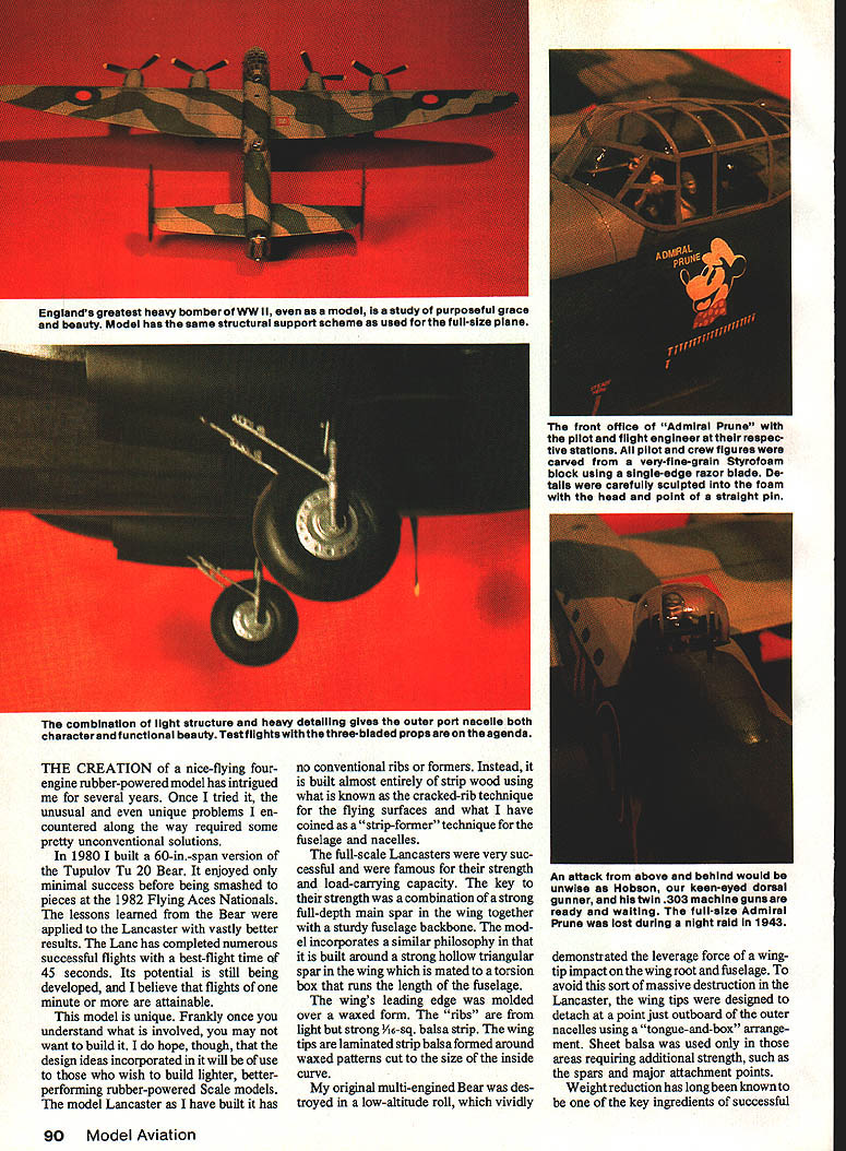
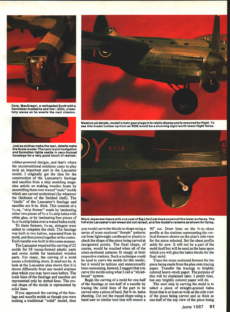
Port navigation and formation lights are nested in vacuum-formed housings for realism. The port outer nacelle contains both character and functional detail; vacuum-formed parts and carved foam crew figures add to the appearance.
Massive yet simple, the main gear plugs in for static display and is removed for flight to lower drag. The tail wheel does not retract.
Wing and tail
Aside from the hollow triangular main spar and the molded leading edge, the wing structure is a conventional cracked-rib design. The tail surfaces are likewise simple. The wing is constructed in two sections, which are joined to the fuselage. Lightweight sheet balsa should be used sparingly for gussets and structural reinforcement of the joints involved.
The Lancaster was built entirely from extremely light, contest-grade balsa from Micro-X Products, P.O. Box 1063, Lorain, OH 44055 (216/282-8354). Great care must be used to select the strongest and lightest balsa available, and Micro-X has always met this vital criterion for me.
Flying — motors, props and launching
- Motors: The prototype Lancaster was flown on two loops of 1/4-in. flat FAI rubber cut to a length of 3.5 times the distance between the peg and hook of each respective nacelle. The motors were lubricated and braided by back-winding to slightly shorten and stiffen them.
- Props: Seven-inch Sleek Streak propellers were cut down to a diameter of 6-3/4 in. for the prototype. Only two-bladed props have been used thus far to fly the model, but flying three-bladed props will add to the realism.
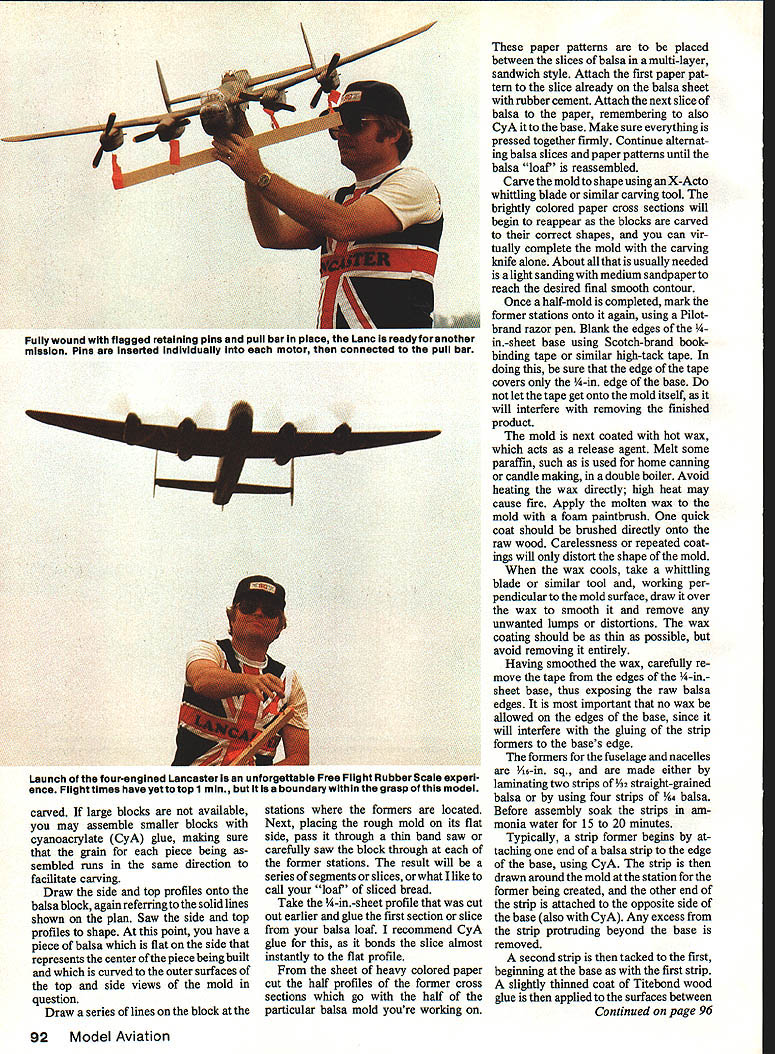
- Motor installation for winding: The fully wound motors are temporarily held in place by placing a 0.08–0.10-in. length of 1/32-in. piano wire vertically through the nacelle so as to pass through the wire hook of each prop assembly. A hook is bent into the lower end of each pin so the pins can be attached through hook-eyes embedded at the appropriate spacings in a piece of 1 x 2-in. pine strip.
- Launching procedure:
- When all motors are wound, the pine strip is pulled down vertically from the plane.
- By simultaneously removing the pins from the prop assemblies, this action permits all the motors to unwind.
- The model is launched horizontally, but firmly, into the prevailing breeze.
Flying three-bladed props is possible and will increase realism, though two-bladed props have been used for test flights. The best recorded flight was 45 seconds; further refinements should yield longer times.
Finishing and rigging details, plus final assembly and flight trimming, are shown on the plan.
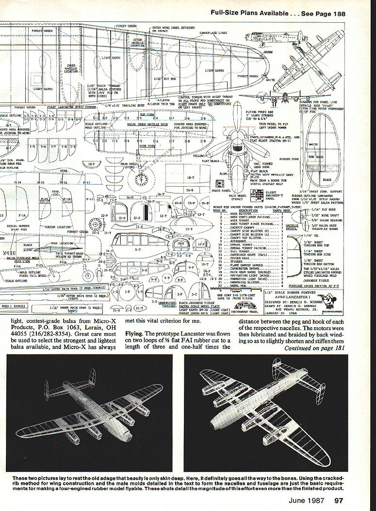
These two pictures lay to rest the old adage that beauty is only skin deep. Using the cracked-rib method for wing construction and the male molds detailed in the text to form the nacelles and fuselage are the basic requirements for making a four-engined rubber model flyable. The photos detail the magnitude of this effort even more than the finished product.
At its best, model aviation captures the beauty and the excitement of manmade flight. Even with this fragile replica, the spark of one of history's great aircraft is rekindled.
Transcribed from original scans by AI. Minor OCR errors may remain.

