
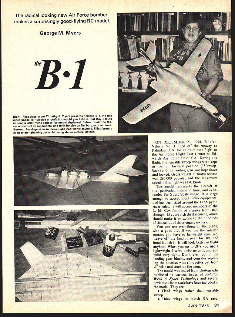
The B·1
The radical looking new Air Force bomber makes a surprisingly good-flying RC model.
George M. Myers
ON DECEMBER 23, 1974, B-1/Air Vehicle No. 1 lifted off the runway at Palmdale, CA, for an 85-minute flight at the Air Force Flight Test Center at Edwards Air Force Base, CA. During the flight, the variable sweep wings were kept in the full forward position (15° sweepback) and the landing gear was kept down and locked. Gross weight at brake release was 280,000 pounds, and the maximum speed in this flight was 190 knots.
This model represents the aircraft at that particular instant in time, and is intended for Sport Scale usage. It is large enough to accept most radio equipment, and has been sized around the 1/2A pylon racer rules. It will accept members of the L. M. Cox family of engines from .049 through .15 cubic inch displacement, which should make it attractive to the hundreds of thousands of those engine owners.
You can use everything on the plans, with a good .15. If you use the smaller motors you have to be weight sensitive. Leave off the landing gear for .09, and hand launch it. It will look better in flight anyhow. When you go to .049 you use a lightweight 2-servo airborne unit, and you build very light. Don't even put in the landing-gear blocks, and consider replacing the nacelles with silhouettes cut from 1/8 balsa and stuck on the wing.
The model was scaled from photographs published in various issues of Aviation Week & Space Technology and several deviations from scale have been included in the model. They are:
- Fixed wings rather than variable sweep.
- Thick wings to match 1/2A racer.
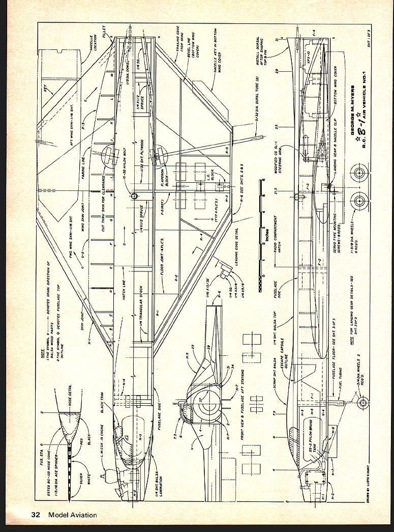
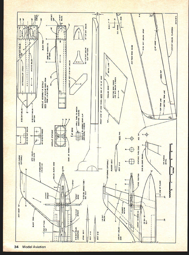
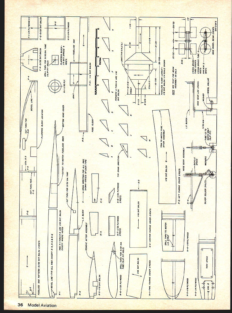
NOTE: THE SYMBOL G DENOTES GRAIN DIRECTION OF BALSA WOOD PARTS
AFT WING SKIN - 1/16 SHT 1/4 SHEET BALSA FWD VIEW
FUSELAGE AFT STATIONS FUSELAGE SIDE
FUSELAGE TOP OUTLINE - NOSE DETACHABLE
FUSELAGE FLOOR - SEE SHEET 3 RADIO COMPARTMENT HATCH
FLAPERON BLOCK 10-32 NYLON BOLT SPRUCE TRAILING EDGE TOP SKIN LINE BOTTOM WING COVER NACELLE KEY IN BOTTOM WING COVER LEADING EDGE DETAIL
BOTTOM SERVO TYPE MOUNTING NACELLE CLIP WING COVER SCREWS - 8-32 1/8 DIA WHEELS
PYLON BAND FUSELAGE SIDE - N-T FUSELAGE SIDE - N-4
MODIFIED CG STEERING ARM INSTALL DORSAL AFTER SHAPING TOP B FIN
3/4 DIA WHEELS
NOTE: FOR LANDING GEAR DETAILS SEE SHT 3 OF 3
GEORGE M. MYERS R.C.-1/4 AIR VEHICLE NO. 1 SHT. 1 OF 3
FWD WING SKIN - 1/16 SHT WING SKIN JOINT ABC FAIRING LINE CUT WING SKIN FOR CLEARANCE
1/4 x 1/8 SPRUCE 1/16 SHT PLYWOOD
1/8 x 1/8 SPRUCE 1/16 SHT PLYWOOD
FUSELAGE FLOOR - SEE SHEET 3 F-S R-F
BOTTOM OF WING - SEE PLAN
FRONT VIEW OF NACELLE ESCAPE CAPSULE OUTLINE
NOTE: SYMBOLS INDICATE PART LOCATIONS AND GRAIN DIRECTION
(Plan details and part callouts shown on drawing)
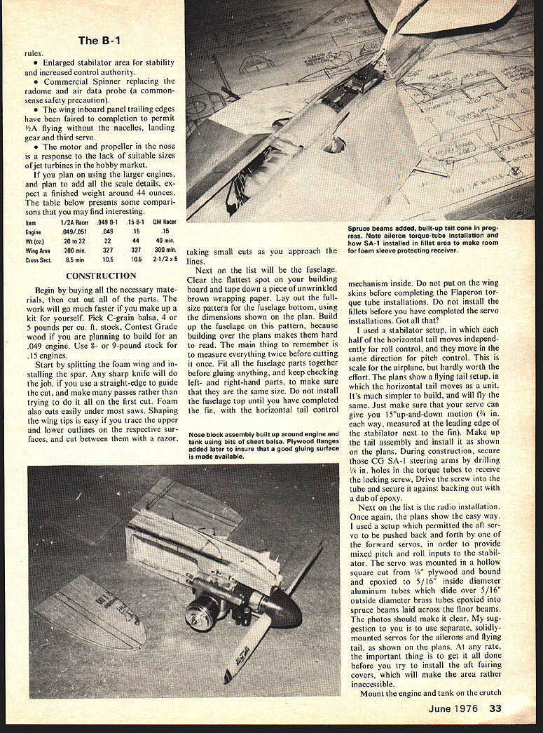
CONSTRUCTION
Begin by buying all the necessary materials, then cut out all of the parts. The work will go much faster if you make up a kit for yourself. Pick C‑grain balsa, 4–5 pounds per cu. ft. stock. Contest Grade wood if you are planning to build for an .049 engine. Use 8–9 pound stock for .15 engines.
Start by splitting the foam wing and installing the spar. Any sharp knife will do the job, if you use a straight‑edge to guide the cut, and make many passes rather than trying to do it all on the first cut. Foam also cuts easily under saws. Shaping the wing tips is easy if you trace the upper and lower outlines on the respective surfaces, and cut between them with a razor, taking small cuts as you approach the lines.
Next on the list will be the fuselage. Clear the flattest spot on your building board and tape down a piece of unwrinkled brown wrapping paper. Lay out the full‑size pattern for the fuselage bottom, using the dimensions shown on the plan. Build up the fuselage on this pattern, because building over the plans makes them hard to read. The main thing to remember is to measure everything twice before cutting it once. Fit all the fuselage parts together before gluing anything, and keep checking left‑ and right‑hand parts, to make sure that they are the same size. Do not install the fuselage top until you have completed the fin, with the horizontal tail control mechanism inside. Do not put on the wing skins before completing the flaperon torque tube installations. Do not install the fillets before you have completed the servo installations. Got all that?
I used a stabilator setup, in which each half of the horizontal tail moves independently for roll control, and they move in the same direction for pitch control. This is scale for the airplane, but hardly worth the effort. The plans show a flying tail setup, in which the horizontal tail moves as a unit. It's much simpler to build, and will fly the same. Just make sure that your servo can give you 15° up‑and‑down motion (3/4 in. each way, measured at the leading edge of the stabilator next to the fin). Make up the tail assembly and install it as shown on the plans. During construction, secure those CG‑SA‑1 steering arms by drilling 1/8 in. holes in the torque tubes to receive the locking screw. Drive the screw into the tube and secure it against backing out with a dab of epoxy.
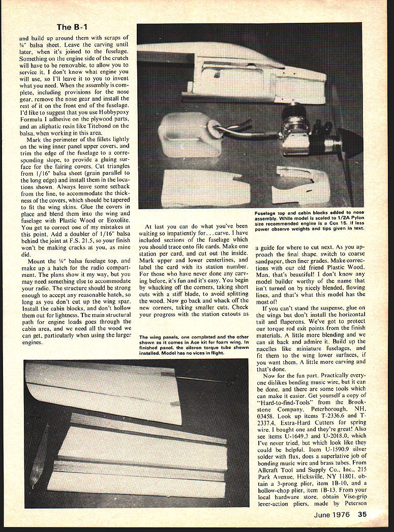
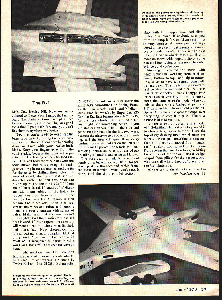
Next on the list is the radio installation. Once again, the plans show the easy way. I used a setup which permitted the aft servo to be pushed back and forth by one of the forward servos, in order to provide mixed pitch and roll inputs to the stabilator. The servo was mounted in a hollow square cut from 1/8 in. plywood and bound and epoxied to 5/16 in. inside diameter aluminum tubes which slide over 5/16 in. outside diameter brass tubes epoxied into spruce beams laid across the floor beams. The photos should make it clear. My suggestion to you is to use separate, solidly‑mounted servos for the ailerons and flying tail, as shown on the plans. At any rate, the important thing is to get it all done before you try to install the aft fairing covers, which will make the area rather inaccessible.
Mount the engine and tank on the crutch. Begin buying necessary materials. Cut out parts — work will go much faster if you make up a kit yourself. Pick C‑grain balsa, 4–5 pounds per cu. ft. stock. Contest‑grade wood. If planning to build for a .049 engine use 4–5 lb. stock; for .15 engines use 8–9 lb. stock.
Start splitting foam for the wing and installing the spar. Any sharp knife will do the job; use a straight‑edge guide and make several light passes rather than trying to cut in one pass. Foam also cuts easily with saws. Shaping wing tips is easy — trace the upper and lower outlines of the respective surfaces and cut between them with a razor, taking small cuts as you approach the lines.
Next on the list will be the fuselage. Clear the flattest spot for your building board.
The B-1
and build up around them with scraps of 1/4" balsa sheet. Leave the carving until later, when it's joined to the fuselage. Something on the engine side of the crutch will have to be removable, to allow you to service it. I don't know what engine you will use, so I'll leave it to you to invent what you need. When the assembly is complete, including provisions for nose gear, remove the nose gear and install the rest of it on the front end of the fuselage. I'd like to suggest that you use Hobbypoxy Formula I adhesive on the plywood parts, and an aliphatic resin like Titebond on the balsa, when working in this area.
Mark the perimeter of the fillets lightly on the wing inner panel upper covers, and trim the edge of the fuselage to a corresponding slope, to provide a gluing surface for the fairing covers. Cut triangles from 1/16" balsa sheet (grain parallel to the long edge) and install them in the locations shown. Always leave some setback from the line, to accommodate the thickness of the covers, which should be tapered to fit the wing skins. Glue the covers in place and blend them into the wing and fuselage with Plastic Wood or Excolite. You get to correct one of my mistakes at this point. Add a doubler of 1/16" balsa behind the joint at F-S 2.1.5, so your finish won't be making cracks at you, as mine did.
Mount the 1/4" balsa fuselage top, and make up a hatch for the radio compartment. The plans show it my way, but you may need something else to accommodate your radio. The structure should be strong enough to accept any reasonable hatch, so long as you don't cut up the wing spar. Install the cabin blocks, and don't hollow them out for lightness. The main structural path for engine loads goes through the cabin area, and we need all the wood we can get, particularly when using the larger engines.
At last you can do what you've been waiting so impatiently for... carve. I have included sections of the fuselage which you should trace onto file cards. Make one station per card, and cut out the inside. Mark upper and lower centerlines, and label the card with its station number. For those who have never done any carving before, it's fun and it's easy. You begin by whacking off the corners, taking short cuts with a stiff blade, to avoid splitting the wood. Now go back and whack off the new corners, taking smaller cuts. Check your progress with the station cutouts as a guide for where to cut next. As you approach the final shape, switch to coarse sandpaper, then finer grades. Make corrections with our old friend Plastic Wood. Man, that's beautiful! I don't know any model builder worthy of the name that isn't turned on by nicely blended, flowing lines, and that's what this model has the most of.
If you can't stand the suspense, glue on the wings but don't install the horizontal tail and flaperons. We've got to protect our torque rod exit points from the finish materials. I can sit back and admire it. Build up the nacelles like miniature fuselages, and fit them to the wing lower surfaces, if you want them. A little more carving and that's done.
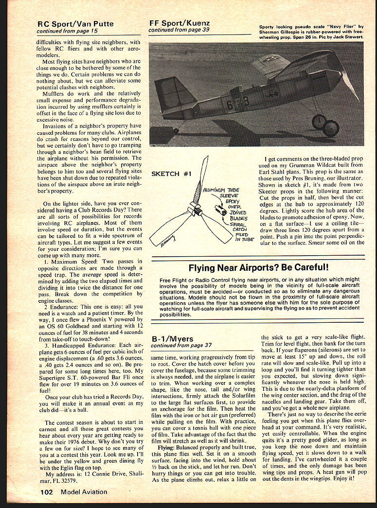
Now for the fun part. Practically everyone dislikes bending music wire, but it can be done, and there are some tools which can make it easier. Get yourself a copy of "Hard-to-find-Tools" from the Brookstone Company, Peterborough, NH 03458. Look up items T-2336.6 and T-2337.4. Extra-Hard Cutters, for spring wire. I bought one and they're great! Also see items U-1649.3 and U-2018.0, which I've never tried, but which look like they could be helpful. Item U-1590.9 silver solder with flux, does a superlative job of binding music wire and brass tubes. From Alcraft Tool and Supply Co., Inc., 215 Park Avenue, Hicksville, NY 11801, obtain a 3-prong plier, item IB-10, and a hollow-chop plier, item IB-13. From your local hardware store, obtain Vise-grip lever-action pliers, made by Peterson This page contains only the full-size plan drawings and part labels for "The B-1" (fuselage, wings, nacelles, hardware details, etc.). There is no continuous article text on this page to extract — the article text continues on other pages.
The B-1
Mfg. Co., Dewitt, NB. Now you are equipped as I was when I made the landing gear. (Incidentally, those free plugs are for your benefit, not mine. They are good tools that I paid cash for, and you don't find them everywhere you look.)
Now that you're ready to work, cut the brass tube parts by rolling the tubes back and forth on the workbench while pressing down on them with your pocket-knife blade. Keep your fingers away from the cutting edge, because the tubes will separate abruptly, leaving a nicely finished surface. Cut and bend the wire parts with the tools above. Before soldering the main gear walking beam assemblies, make a jig for the axles by drilling three holes in a piece of wood, along a straight line, 1/8" diameter each. The first two holes are 27/32" apart, and the third is 29/32" from one of them. Install 1" lengths of 1/8" diameter aluminum tubing in the holes, to support the brass tubes which form the bearings for our axles. Aluminum is used because the solder won't stick to it. Assemble the wires and tubes, and support them in proper alignment with scraps of balsa. Make sure that the wire doesn't fit so tightly that the aluminum tubes are bent inward. If this happens, the assembly will want to roll in a circle when finished, and that's bad. Now silver-solder the joints, getting a nice, complete fillet at every joint. You can do this with a 27 Watt, 650°F iron, such as is used in radio work, and there will be more than enough heat.
I might mention here that I couldn't find a source of reasonably scale wheels, so I used slot car wheels, T-5 made by Twinn-K, Inc., Box 31228, Indianapolis, IN 46231, and sold on a card under the name AJS Miniature Car Racing Parts, for the main wheels, and I used 3/4" diameter Super Jet wheels, by Super Jet, 826 Conklin St., East Farmingdale, NY 11735, for the nose wheels. Shop around a bit, you might find something better. If you use slot car wheels, talk to the man and get something made in the last two years, because the older wheels had poorer bonding, and the tires will spin off on every landing. Use wheel collars on the left side of the plane to prevent the wheels from unscrewing themselves, since slot car wheels are all right-hand-thread, as far as I know.
The nose gear is made by a series of bends on a bicycle spoke, 10" or longer, starting at the threaded end, which forms the main attachment. When you've got it done, bind the short parallel section in place with fine copper wire, and silver-solder it in place. If anybody asks you what the lump is for, tell them that it's a shimmy damper. All nose gear are supposed to have them, but a surprising number of models don't. Solder in the axle tube, bolt on the wheels with a 3/8-48 x 1 machine screw, with stopnut, slip on some pieces of fuel tubing to represent the outer cylinder, and you're done.
Finishing: I covered the model with white Solarfilm, working from back-to-front, bottom-to-top, and tip-to-centerline, so as to have all seams facing aft, out and down. This limits lifting caused by fuel penetration and wind pressure. Trim was black Monokote, black Tactype 4948 letters (which you buy at an art supply store) that transfer to the model when you rub on them with a ball-point pen, and 1/2" stars-and-bars from an old plastic kit. Spray Aero-gloss fuel-proofer dope over everything, to keep it in place. The nose ribbon is blue Monokote.
A note or two on covering this model with Solarfilm. The best way to proceed is to clear a large space to work. I use the top of my drawing table, which measures 40 x 72. Next, put something on that surface to protect your model from "hangar rash" (nicks and scratches that come from setting the model on tools, or hitting the corners of the table). I use a wedge-shaped foam pillow for the purpose. Provide yourself with a fireproof place to set the Monokote iron.
Always try to shrink both sides at the
B-1/Myers
continued from page 37
same time, working progressively from tip to root. Cover the hatch cover before you cover the fuselage, because some trimming is always needed, and the airplane is easier to trim. When working over a complex shape, like the nose, tail and/or wing intersections, firmly attach the Solarfilm to the large flat surfaces first, to provide an anchorage for the film. Then heat the film with the iron or hot air gun (preferred) while pulling on the film. With practice, you can cover a tennis ball with one piece of film. Take advantage of the fact that the film will stretch as well as it will shrink.
Flying: Balanced properly and built true, this plane flies well. Set it on a smooth surface, facing into the wind, hold about 1/3 back on the stick, and let her run. Don't hurry things or you can get into trouble. As the plane climbs out, relax a little on the stick to get a very scale-like flight. Trim for level flight, then bank for the turn back. If your flaperons (ailerons) are set to make at least 15° up and down, the roll will be slow and scale-like. Pull up into a loop and you'll find it turning tighter than you expected, but slowing down significantly whenever the nose is held high. This is due to the nearly-delta planform of the wing center section, and the drag of the nacelles and landing gear. Take them off, and you've got a whole new airplane.
There's just no way to describe the eerie feeling you get when this plane flies overhead at your command. It's very realistic, yet easily controllable. When the engine quits it's a pretty good glider, as long as you keep the nose down and maintain flying speed, yet it slows down to a walk for landing. I've crashed a couple of times, and the only damage has been wingtips and props. A heat gun will pop out the dents in the wingtips. Enjoy it!
Transcribed from original scans by AI. Minor OCR errors may remain.

