
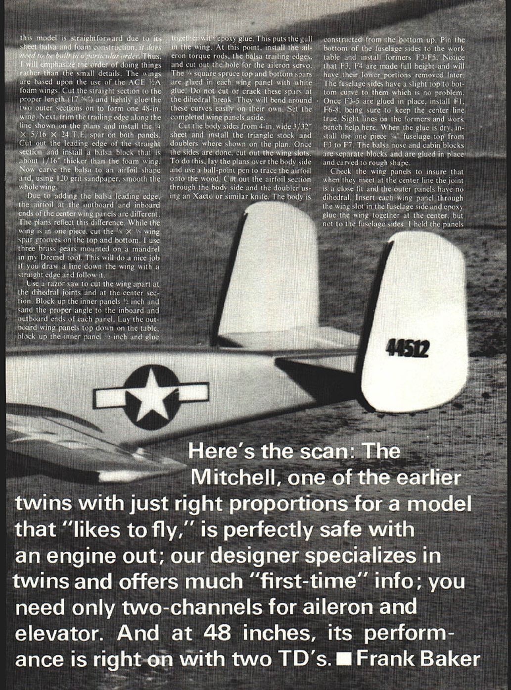
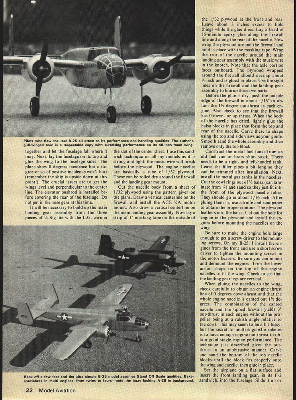
The B-25
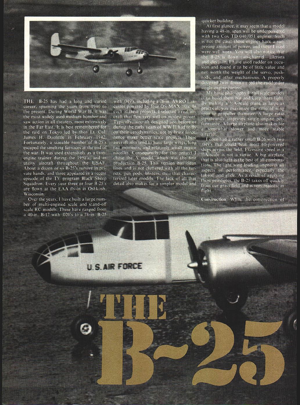
The B-25 has had a long and varied career, spanning the years from 1940 to the present. During World War II it was the most widely used medium bomber and saw action in all theaters, most extensively in the Far East. It is best remembered for the raid on Tokyo led by then Lt. Col. James H. Doolittle in February 1942. Fortunately, a sizeable number of B-25s escaped the smelting furnaces at the end of the war. It was used extensively as a twin-engine trainer during the 1950s and as a utility aircraft throughout the USAF. About a dozen or so B-25s survive in private hands, and three appeared in a recent episode of the TV program Black Sheep Squadron. Every year three or four B-25s are flown at the EAA fly-in in Oshkosh, Wisconsin.
Over the years I have built a large number of multi-engined scale and stand-off scale RC models. These have ranged from a 40-inch B-17 with .020 engines to a 78-inch B-25 with .049s, including a 76-inch Avro Lancaster powered by four OS MAX-10s. In each of these projects I selected a real aircraft that flew very well on modest power. Typically, aircraft designed just before or during the early years of WWII had to fly on their aerodynamics rather than by brute force, hence they make better scale projects. These aircraft also tend to have large wings, long tail moments, and relatively small engine nacelles. Consequently, for this project I chose the A model, which was the first production B-25. This version has clean lines and is not cluttered with the turrets, gun pods, blisters, etc., that characterized later models. The lack of that detail also makes for a simpler model and quicker building.
At first glance it may seem that a model having a 48-inch span will be underpowered with two Cox TD .049/.051 engines. Such is not the case; those engines have a surprising amount of power, and those I used were well worn. You will also notice that the B-25 is flown two-channel — ailerons and elevator. I have used rudder on occasion and found it to be of little value and not worth the weight of the servo, pushrods, and other mechanisms. A properly designed twin doesn't need the rudder for single-engine control.
My basic philosophy for all scale models is to build them big and keep them light. By making a 1/4-scale plane as large as practical, you maximize the ratio of wing span to propeller diameter. A large ratio significantly improves single-engine performance. A large airplane also makes for a somewhat slower and more stable aircraft.
I once had a rather small B-26 with two .049s that could beat most .60-powered ships across the field. Excessive speed in a 1/4-scale is not a virtue. A big airplane that is also light is the best of all combinations. The light wing loading improves all aspects of performance, especially takeoff and glide. As a result of applying these principles, the B-25 takes off quickly from our grass field and is very realistic in flight.
Construction
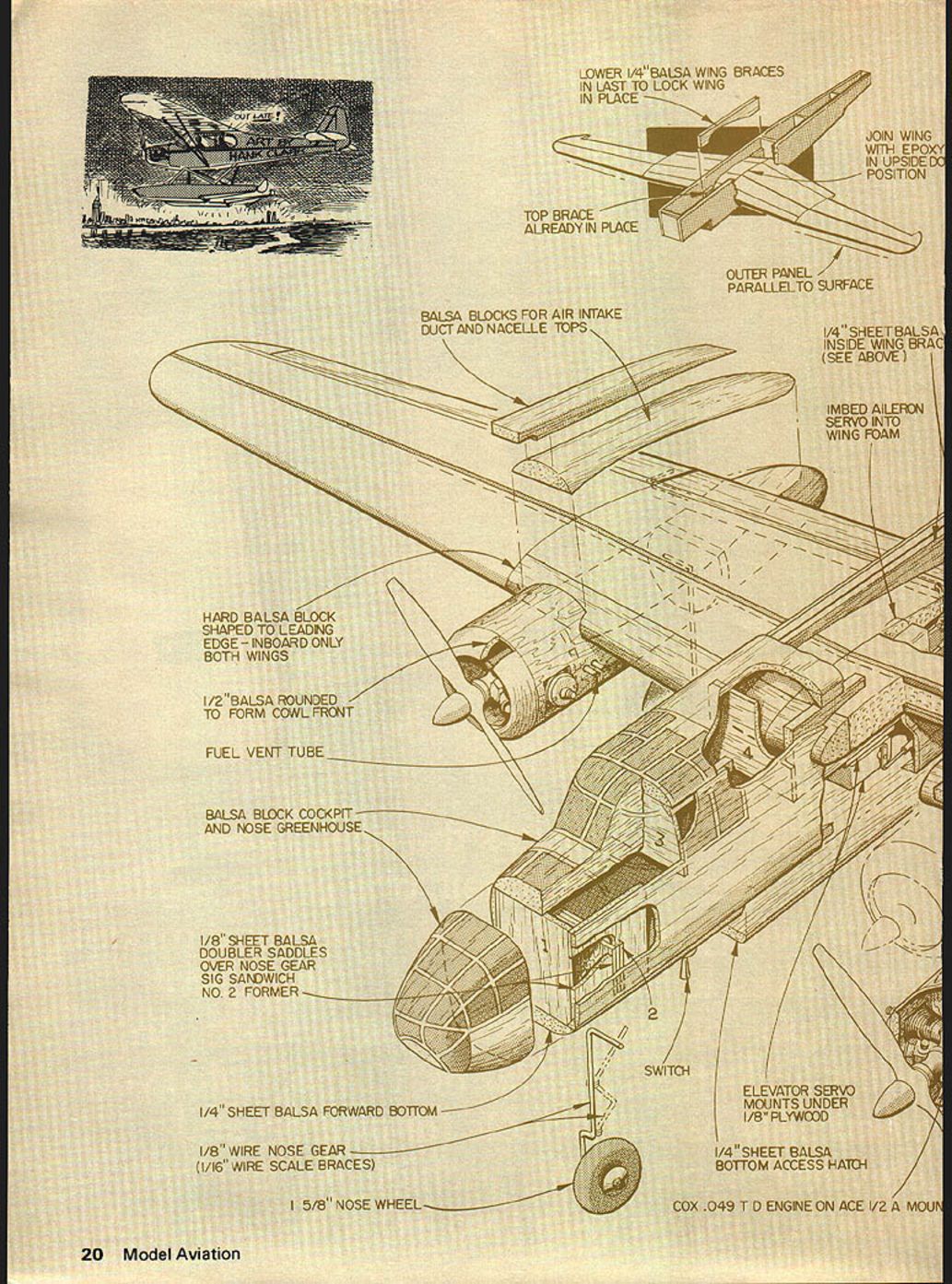
The construction of this model is straightforward due to its sheet-balsa and foam construction, but it does need to be built in a particular order. The emphasis here is on the sequence of operations rather than every small detail.
Wing construction
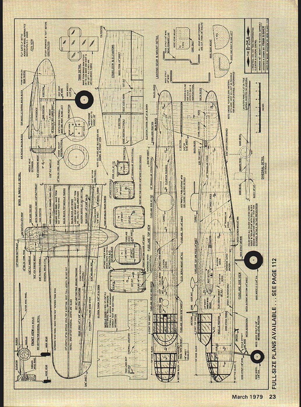
- The wings are based upon the use of ACE 1/4" foam wing sections. Cut the straight section to the proper length (17 1/2") and lightly glue the two outer sections on to form one 48" wing.
- Trim the trailing edge along the line shown on the plans and install the 1/8 x 5/16 x 24 T.E. spar on both panels.
- Cut out the leading edge of the straight section and install a balsa block that is about 1/16" thicker than the foam wing. Carve the balsa to an airfoil shape and, using 120-grit sandpaper, smooth the whole wing.
- Because of the added balsa leading edge, the airfoil at the outboard and inboard ends of the center wing panels are different. The plans reflect this difference.
- While the wing is in one piece, cut the 1/8 x 3/16" wing spar grooves on the top and bottom. I use three brass gears mounted on a mandrel in my Dremel tool — draw a straight line down the wing and follow it.
- Use a razor saw to cut the wing apart at the dihedral joints and at the center section. Block up the inner panels 1/2" and sand the proper angle to the inboard and outboard ends of each panel.
- Lay the outboard wing panels top down on the table, block up the inner panel 1/8", and glue together with epoxy. This puts the gull in the wing.
- Install the aileron torque rods, the balsa trailing edges, and cut out the hole for the aileron servo.
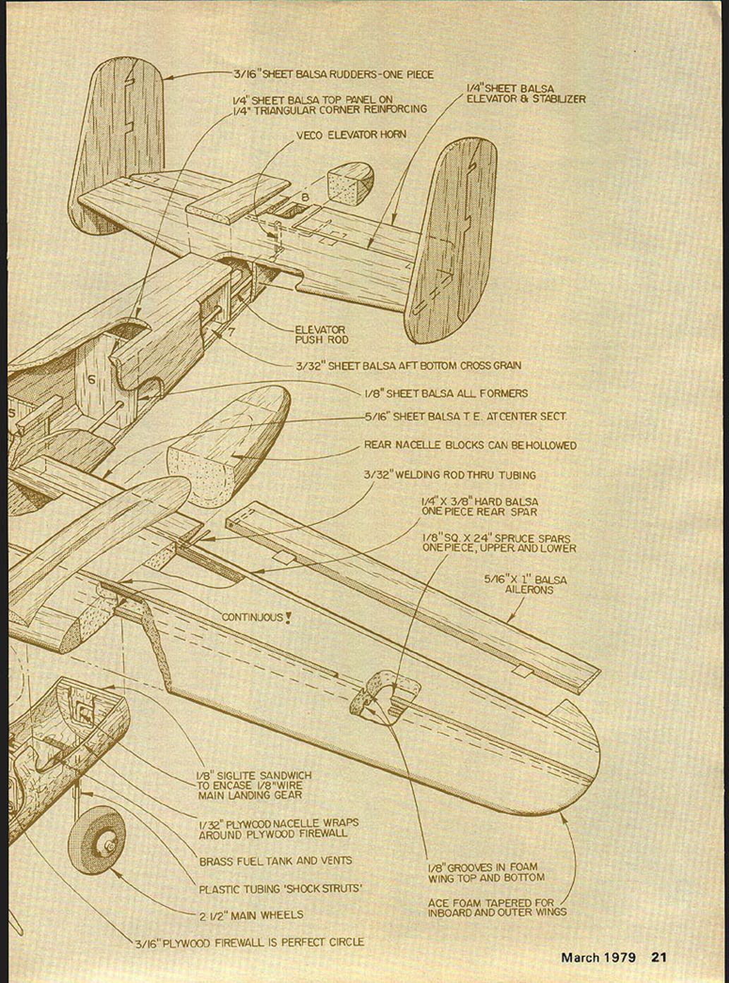
- Glue 1/8" square spruce top and bottom spars in each wing panel with white glue. Do not cut or crack these spars at the dihedral break — they will bend around the curves easily on their own.
Set the completed wing panels aside.
Fuselage construction
- Cut the fuselage sides from 4" wide 3/32" sheet balsa and install triangle stock and doublers where shown on the plans. Once the sides are done, cut out the wing slots by laying the plans over the body side and tracing the airfoil with a ball-point pen. Cut out the airfoil section through the body side and doubler with a sharp knife.
- Construct the body from the bottom up. Pin the bottom of the fuselage sides to the work table and install formers F3–F5. Note that F3 and F4 are made full height; their lower portions will be removed later.
- The fuselage sides have a slight top-to-bottom curve; this is normal. Once F3–F5 are glued in place, install F1 and F6–F8, keeping the centerline true. Sight lines on the formers and workbench help here.
- When the glue is dry, install the one-piece F1 fuselage top from F3 to F7. The balsa nose and cabin blocks are separate and are glued in place and carved to rough shape.
Check the wing panels to ensure that when they meet at the center line the joint is a close fit and the outer panels have no dihedral. Insert each wing panel through the wing slot in the fuselage side and epoxy-glue the wing together at the center, but not to the fuselage sides. Hold the panels together while the epoxy sets by using masking tape on the top and bottom.
When the wing assembly is made, install the nacelle center box from the bottom up through the wing slot. Make the nacelle sides from 1/8" sheet and glue them to the wing and center box structure. The nacelles are tapered and hollow to reduce weight. Install the engine mounts and ring for the cowlings. Cut the balsa to make the top nacelle curve and carve to shape. Use 1/16" plywood for the firewall and mount the engine bearers. After aligning the nacelles, glue the landing gear mounts and fairings in place.
Nacelle, engine and fuel installation
- The main landing gear assembly is a sandwich of three pieces of 1/8" Sig-lite with the L.G. wire in the center sheet. This sandwich technique is strong and light; the music wire will break before the plywood if overloaded.
- The engine nacelles are basically a tube of 1/32" plywood. Cut the nacelle body from 1/32" plywood using the pattern on the plans.
- Draw a vertical centerline on the firewall and install the ACE 1/4A motor mount. Draw a vertical centerline on the main landing gear assembly as well.
- Lay a strip of 1" masking tape on the outside of the 1/32" plywood at the front and rear, leaving about 3" excess to hold things while the glue dries. Lay a bead of 15-minute epoxy along the firewall line and along the rear of the nacelle, wrap the plywood around the firewall and hold with masking tape. Wrap the rear of the nacelle around the main landing gear assembly with the music wire in the slot, axle portion facing outboard. The plywood wrapped around the firewall should overlap about 1/4" and is glued in place.
- Before the glue dries, push the outside edge of the firewall in about 1/16" to obtain 1 1/2° out-thrust in each engine. Also check to see that the firewall has zero down- or up-thrust.
- When the nacelle body has dried, lightly glue balsa blocks that form the top and rear of the nacelle and carve them to shape. Smooth-sand the entire assembly and then remove only the top block for later fitting.
- Construct metal fuel tanks from an old fuel can or brass shim stock; you need right- and left-handed tanks. Leave the filler pipes a bit long for trimming after installation. Install the metal tanks in the nacelles.
- Cut cowl rings from 1/8" balsa (or laminate from 1/4") and sand so they just fit into the front of the plywood nacelle tubes (about 1/16" in). Glue them in and contour the joint so the plywood feathers into the balsa.
- Cut the engine hole in the plywood and install the engines before mounting the nacelles on the wing. Make the engine hole large enough to get a screwdriver to the mounting screws. I install the engines from the front and use a short screwdriver to tighten the mounting screws in the motor bearers — be sure you can mount and demount the engines.
- Trim the lower airfoil shape on the top of the engine nacelles to fit the wing. Check that the landing gear legs are vertical.
When gluing the nacelles to the wing, carefully obtain an engine thrust line of 0° down-thrust and that the whole nacelle is canted out 1 1/2°. The combination of the canted nacelle and the tipped firewall yields about 3° out-thrust in each engine without the propeller being at a rakish angle relative to the cowl. This provides unobtrusive engine out-thrust for good single-engine performance. Carve and sand the bottom of the top nacelle blocks until they fit properly onto the wing and nacelle, then glue in place.
Final assembly and fit-up
- Set the airplane on a flat surface and insert the front landing gear (in its F-2 sandwich) into the fuselage. Slide it up or down until the nose gear is about 1/8" longer than the main gear — this positive angle of attack aids takeoff.
- Remove the bottom two-thirds of F3 and F4 at this point.
- Install the front lower fuselage along with the hatch and its hold-downs. Final-sand the cockpit and nose area.
- Use a draftman's triangle to ensure the rudders are perpendicular to the stabilizer.
- For the rear of the nacelles you can carve balsa blocks, or use 2" thick styrofoam — it’s easy and very light.
- Install the elevator pushrod before covering the rear of the fuselage. Do not install the nose gear until later in the build sequence.
- When the wing is glued to the fuselage sides, make sure the wings are level and perpendicular to the centerline. The plans show 0° incidence, but a degree or so of positive incidence won’t hurt. The crucial points are correct wing level and alignment.
Full-size plans available: see page 112.
Construction notes and callouts (from the plans)
- Lower 1/4" balsa wing braces insert to lock wing in place
- Top brace already in place
- Join wing with epoxy in upside-down position
- Outer panel parallel to surface
- 1/4" sheet balsa inside wing brace
- Balsa blocks for air intake duct and nacelle tops
- Imbed aileron servo into wing foam
- Hard balsa block shaped to leading edge — inboard only (both wings)
- 1/2" balsa rounded to form cowl front
- Fuel vent tube
- Balsa block cockpit and nose greenhouse
- 1/8" sheet balsa doubler saddles over nose gear
- Sig sandwich no. 2 former
- 1/4" sheet balsa forward bottom
- 1/8" wire nose gear (1/16" wire scale braces)
- 1 5/8" nose wheel
- Switch
- Elevator servo mounts under 1/8" plywood
- 1/4" sheet balsa bottom access hatch
- Cox .049 T.D. engine on ACE 1/2A mount
- 3/16" sheet balsa rudders — one piece
- 1/4" sheet balsa top panel on 1/4" triangular corner reinforcing
- 1/4" sheet balsa elevator & stabilizer
- VECO elevator horn
- Elevator pushrod
- 3/32" sheet balsa aft bottom cross grain
- 1/8" sheet balsa all formers
- 5/16" sheet balsa T.E. at center section
- Rear nacelle blocks can be hollowed
- 3/32" welding rod thru tubing
- 1/4" x 3/8" hard balsa one-piece rear spar
- 1/8" sq. x 24" spruce spars one piece, upper and lower
- 5/16" x 1" balsa ailerons
- Continuous!
- 1/8" Siglite sandwich to encase 1/8" wire main landing gear
- 1/32" plywood nacelle wraps around plywood firewall
- Brass fuel tank and vents
- Plastic tubing "shock struts"
- 2-1/2" main wheels
- 3/16" plywood firewall is perfect circle
- 1/8" grooves in foam wing top and bottom
- ACE foam tapered for inboard and outer wings
Finishing
The fuselage and nacelles are given several coats of filler and sanded smooth between each coat. For color I used silver Aero Gloss. The wings, elevator, and rudders are covered with silver Solar Film. The color match between Aero Gloss and Solar Film is excellent and one can hardly tell where the changeover occurs.
Cabin windows are painted on with black dope. Insignia and de-icer boots are cut from MonoKote Trim Film. (For greater detail on finishes and markings, see Profile Publications No. 59.) The plans show the turret and radio direction finder, but I did not install them. They are shown on the plans for those who have a greater love of detail.
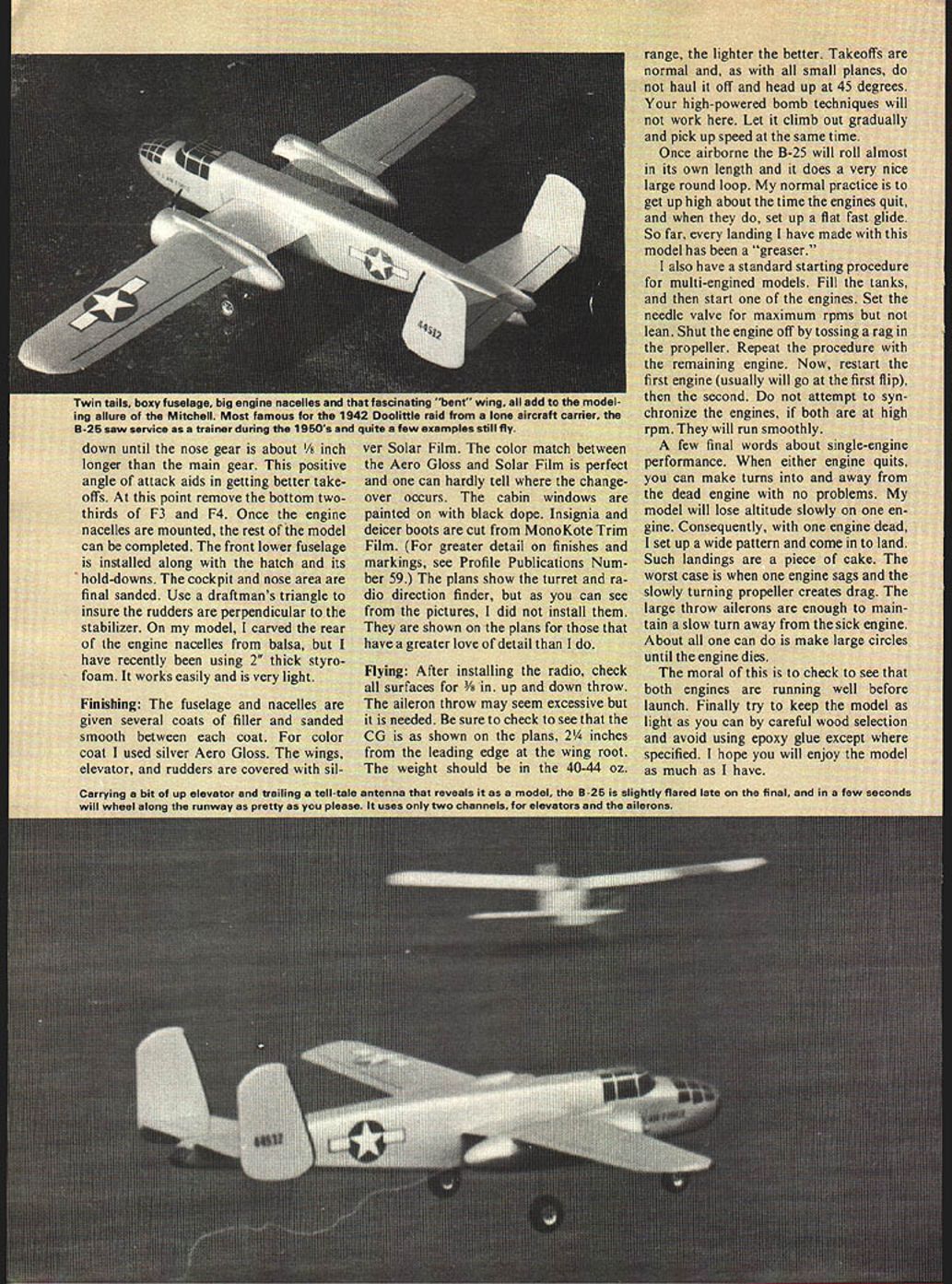
Flying
After installing the radio, check all surfaces for 3/16" up and down throw. The aileron throw may seem excessive but it is needed. Be sure the CG is as shown on the plans: 2-1/4" from the leading edge at the wing root. The weight should be in the 40–44 oz. range — the lighter the better.
Takeoffs are normal. As with all small planes, do not haul it off and pitch up steeply; let it climb out gradually and pick up speed at the same time. Once airborne the B-25 will roll almost in its own length and will do a very nice, large round loop. My normal practice is to get up high; when the engines quit, set up a flat fast glide. So far, every landing I have made with this model has been a "greaser."
Engine starting procedure
I use this standard starting sequence for multi-engined models:
- Fill the tanks.
- Start one engine and set the needle valve for maximum RPMs but not lean. Shut the engine off by tossing a rag in the propeller.
- Repeat the procedure with the remaining engine.
- Restart the first engine (usually will go on the first flip), then start the second.
- Do not attempt to synchronize the engines; if both are at high RPM they will run smoothly.
Single-engine performance
When either engine quits you can make turns into and away from the dead engine with no problems. My model will lose altitude slowly on one engine. With one engine dead I set up a wide pattern and come in to land — such landings are a piece of cake.
The worst case is when one engine sags and the slowly turning propeller creates drag. The large-throw ailerons are enough to maintain a slow turn away from the sick engine. Generally, all you can do is make large circles until the engine dies.
The moral is to check that both engines are running well before launch. Finally, try to keep the model as light as you can by careful wood selection and avoid using epoxy except where specified.
I hope you enjoy the model as much as I have.
Transcribed from original scans by AI. Minor OCR errors may remain.

