
A-B Shrike
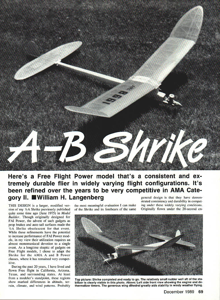
Here's a Free Flight Power model that's a consistent and extremely durable flier in widely varying flight configurations. It's been refined over the years to be very competitive in AMA Category II. — William H. Langenberg
This design is a larger, modified version of my 1/2A Shrike, previously published (June 1975) in Model Builder. Though originally designed for FAI Power, the advent of such gadgets as prop brakes and auto tail surfaces made the 1/2A Shrike obsolescent for that event. While these refinements have the potential to increase performance of FAI Power models, their utilization often requires an almost monomaniacal devotion to a single event. As a longtime skeptic of gadgets on Free Flight models, I chose to adapt the Shrike for the AMA A and B Power classes, where it has remained very competitive.
During the past 20 years I have lived and flown Free Flight in California, Arizona, Texas, and surrounding states. From a modeler's standpoint, these regions show marked differences in altitude, terrain, climate, and wind patterns. Probably the most meaningful evaluation I can make of the Shrike and its forebears of the same general design is that they have demonstrated consistency and durability in competing under these widely varying conditions.
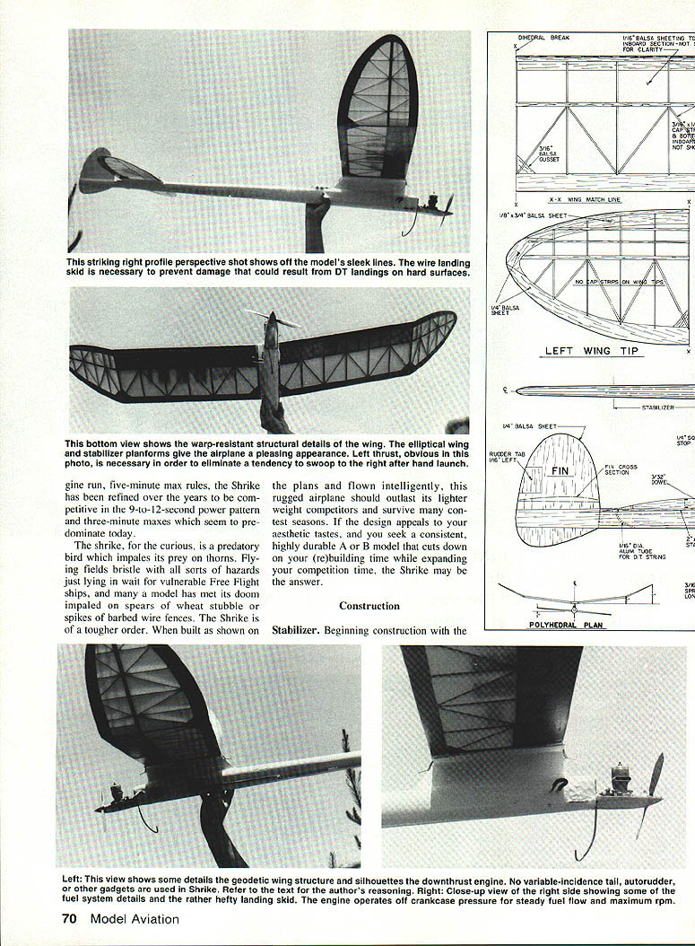
Originally flown under the 20-second engine-run, five-minute-max rules, the Shrike has been refined over the years to a competitive 9-to-12-second power pattern. Three-minute maxes seem predominant today. The shrike, a curious predatory bird, impales its prey on thorns. Flying fields bristle with hazards just lying in wait for vulnerable Free Flight ships — models have met their doom on impaled spears, wheat stubble spikes, and barbed-wire fences. The Shrike is a tougher order; built as shown on the plans and flown intelligently, this rugged airplane should outlast its lighter-weight competitors and survive contest seasons.
The design appeals to aesthetic tastes and to those who seek a consistent, highly durable B model. It cuts down rebuilding time and expands competition time. Shrike may answer.
Construction
Stabilizer
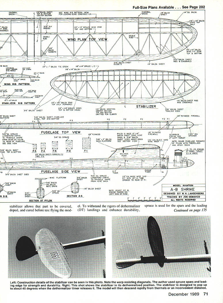
Beginning construction with the stabilizer allows that part to be covered, doped, and cured before test flying the model. To withstand the rigors of dethermalizer (DT) landings and enhance durability, spruce is used for the spars and the leading edge. If minimizing weight is your ultimate building criterion, you may substitute balsa, although this is not recommended.
The stabilizer should be covered with tissue and given at least three coats of thinned dope. I generally prefer nitrate to butyrate dope because it appears less susceptible to moisture changes in the air. If nitrate dope is used, a coat of fuel-proofer must be applied as the final step.
See that the stabilizer is absolutely free of warps, and ensure that it remains so by strapping it with one or two turns of rubber bands to a flat board for storage.
Wing
With the relatively straightforward building techniques, simplified by the flat-bottomed airfoil, you should have few problems. Balsa may be substituted for the spruce spars on the plans, though again it isn't recommended. Select the wood for the wings with care, as they should be kept as light as possible.
For the two inboard wing panels, ribs should be cut from 3/32" quarter-grained stock. The trailing edges are preferably carved from 1/4" sheet balsa with similar grain. Assemble the wing panels to the polyhedral dimensions indicated, liberally gluing all joints. Install plywood gussets and triangular interconnects as shown. Sand the entire completed structure carefully to ensure an attractive covering job.
I recommend covering the inboard wing panels with G/M Silkspan or silk over tissue. If the latter method is used, first water-shrink the tissue and apply one coat of dope to the wing and allow it to dry. Then apply the silk, shrink it with water, and finish with additional coats of dope. The result is a very taut double covering, relatively impervious to changes in temperature or moisture, which enhances torsional rigidity of the wing.
The wing tips should be tissue covered. As on the stabilizer, apply at least three coats of nitrate dope on the wing plus fuel-proofer on the inboard panels. Set the wing aside and allow it to cure thoroughly. The right inboard wing panel should have 1/2" of wash-in.
Fin
Cut this part from 1/4" soft balsa sheet to the outline shown on the plan. Carve and sand it to a streamlined shape as indicated.
Fuselage
- Select four 3/16" x 3/16" straight-grained spruce strips for the longerons. Carve them to triangular shape starting about 3" aft of Section A as indicated on the plan.
- Cut two fuselage sides from 1/16" soft balsa. Pin one side over the plan, and glue on the longerons. Insert 1/8" balsa bulkheads just forward and aft of the pylon, spacing them as shown on the plan.
- Remove the first fuselage side from the plan, and glue the shaped longerons to the second side. When the longerons are dry, attach this side to the bulkheads, making sure in doing so that the entire fuselage is properly aligned.
- Select a sheet of medium 3/16" balsa for the fuselage bottom. Sand smooth the bottom of the two fuselage sides, longerons, and connecting bulkheads, and then glue the entire assembly to the bottom sheet. Pin this entire structure to a flat surface if desired.
- Cut the pylon, very accurately, from hard 1/8" sheet balsa, notch it for the bulkheads, and glue it firmly in place. Ensure that it is perfectly vertical.
- Sand the fuselage top, and attach the 3/32" cover sheet along its entire length. Glue the 3/16" soft sheet pylon sides in place. Prepare the wing and stabilizer platforms as shown on the plan.
Remove the fuselage assembly from the plan when dry. Cut and drill the 1/8" plywood firewall to fit one of the commercially available aluminum engine pans. Install blind mounting nuts, and epoxy the firewall to the fuselage forward bulkhead as shown on the plan. File, carve, and sand the forward fuselage into a smooth configuration to ensure a clean junction with the engine mount. Cover this entire area with fiberglass and epoxy resin.
Sand the balance of the fuselage smooth, then add the wing and stabilizer platforms. Slot the fuselage for the fin, insert it as shown on the plan, check alignment, and glue it in place. Add the 3/32" spruce dowel for the DT bands, then the tubing for the external DT string.
Bind the wing hooks from 1/16" wire as shown on the plan, and epoxy them firmly in place. Sand smooth the entire fuselage and apply two coats of clear dope. Install the engine and DT timers.
I normally apply two coats of epoxy paint as a fuselage finish, primarily because it is durable and absolutely fuel-proof. If desired, however, the fuselage can be tissue-covered and doped. Ensure that adequate fuelproofing is applied if the latter procedure is used.
The original A-B Shrike used a pressure fuel system which is illustrated in the plans and photographs. A pressure-balloon system can be used if preferred. Install a .15–.23-size engine of your choice, and prepare the model for flight testing.
Flight testing
For a hot A-B model like the Shrike, the first few test flights are usually the most critical. If the airplane passes that crucible without mishap, the remaining flights become easier.
Before attempting the first test flight, check the model carefully for proper alignment, center-of-gravity location, and freedom from warps. Do a test glide, and adjust the plane as necessary by small increments of packing under the leading or trailing edge of the stabilizer. Hand glides should reveal a slight right turn, produced by adjusting the stab tilt.
Once the glide is satisfactory, the ship is ready for its first power flight. Set the engine timer for not more than a three-second run, start the engine, and hand-launch the model gently into the wind at about a 45° elevation. Climb should be straight out at the angle of launch and into a slight right spiral.
If you observe any tendency to veer leftward in the climb, correct it immediately; it's generally a fatal condition.
On subsequent test flights, increase the length of engine run as flight pattern and safety (not to mention your intestinal fortitude) permit. All of my models of this general design have required about 3/8" of left rudder tab to keep the tail down during climbout. The 1/8" of wash-in in the right inboard wing panel helps keep the latter up during ascents.
One word of caution: if using the Shrike interchangeably in classes A and B, repeat the test procedure upon switching engines. Nothing affects the Shrike's climb pattern more drastically than major changes in power (or speed). Unless you are absolutely certain that your A and B engines have equal power output, it's prudent to do a few short test flights after changing engines.
With a full 9-to-12-second engine run, this model should make one or two full turns to the right during climb and enter its glide pattern with no stall or loss in altitude. If the airplane is built according to the plans, flight patterns will naturally be right-right.
Competition durability
When built as shown, ready-to-fly weight is about 24 to 26 ounces. In my opinion, assuming that a hot engine is used, this extra weight won't noticeably reduce performance — and the rugged construction will carry the model through several contest seasons. Modelers with limited building time, or who simply prefer competing to building, will find the Shrike's longevity a great advantage.
At the risk of being an iconoclast, I offer one suggestion to enhance the model's durability even further: minimize unnecessary testing. Once the wing and stabilizer have been glued, the model is properly adjusted, and the model has proven competition-worthy, little additional testing is necessary. Probably two or three short DT flights before a contest should suffice. If those who question this philosophy will take a moment to recall how many folded wings, damaged models, or lost Free Flight ships have, in their experience, been traceable to superfluous test flights, I think they'll concede my point.
Transcribed from original scans by AI. Minor OCR errors may remain.

