
Babe Bee Voyager
Overview
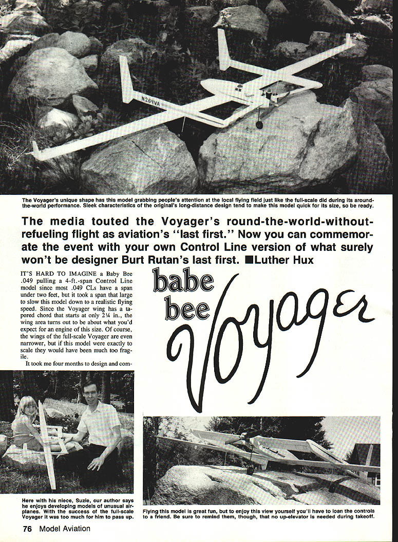
The media touted the full-scale Voyager's round-the-world, nonrefueled flight as aviation's "last first." This is a Control Line (CL) tribute version of Burt Rutan's design, scaled and simplified for .049 power. Although it's hard to imagine a Baby Bee .049 pulling a 4 ft span CL model (most .049 CLs have spans under 2 ft), the 4 ft span slows the model to a realistic flying speed. The Voyager wing has a tapered chord starting at only 2¼ in., so the wing area is appropriate for an engine of this size. If made exactly to scale, the wings would have been much too fragile.
I completed a 9 ft RC Voyager over four months and found it a difficult project; this CL version was done in four nights and should be enjoyable for most builders as an express version.
Flight Characteristics and Warnings
Flight behavior
- Using the center-of-gravity (CG) location predicted by John Hunton's calculations, the model flew perfectly right off the drawing board.
- However, initial landings were catastrophic: right after the engine quit the models dove straight into the ground in spite of full-up elevator.
- The problem was excessive load on the foreplane (canard). It could not support its end of the model unless the model was flying at high speed.
Fixes applied
- Increased the canard angle and area.
- Moved the CG rearward to lessen the load the canard must support.
- Added downthrust to the engine mount to compensate for the lighter loading on the canard during powered flight.
John Hunton’s calculation method is valid but needed adjustment for this small model. With the changes, the model now glides reasonably and lands without constant repairs.
Two very important warnings
- Do not apply up elevator during takeoff.
- The canard is already at an 8° angle at neutral; additional up elevator can cause trouble.
- Burt Rutan advised that the airplane does not rotate on takeoff but must fly off the runway. In tests the models lifted off by themselves (usually) at 10–15 ft on pavement with the stick and elevator neutral.
- Pay attention to the Y-shaped pushrod setup.
- The combination of elevator angles and the pushrod spacing can create a snapping action when the lines go slack, which can force the elevators up or down.
- The spacing between the Z-bends on the pushrod ends must match the spacing of the control horns. The elevator must float freely and not toggle. If incorrectly set, the model will dive or climb whenever the lines go slack.
- When correctly set up, the model will land itself if kept level with the engine idling.
Additional flight notes
- Do not attempt maneuvers if the model slows down.
- When the engine quits, lead the model by towing the lines; add up elevator progressively until it lands.
- This design does not respond to flaring attempts in this size (and reportedly not in full scale). Burt Rutan: "Fly it off and fly it on."
Free Flight and Field Notes
- As a free flighter the model performs well; I’ve had the wind blow it inside the circle several times and it stayed level while I tightened the lines.
- Pavement is the best surface for takeoffs and landings but also the most likely to damage the model. Pavement is required due to the short landing gear spacing. Dirt baseball diamonds work well; grass takeoffs were not achievable in my tests.
- Winglets are fragile—some builders remove them after repeated breakage. The full-scale Voyager may have flown without them.
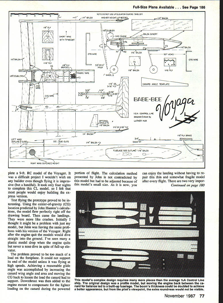
Construction
Materials and general
- Use medium to medium-hard balsa for all parts. The structure is too thin for soft balsa.
- 1/16" balsa for bottom sheeting.
- 1/16" plywood was used for prototype rudders; 3/8" plywood can be used to reduce required tail weight and increase strength.
- Do not groove the wing for landing-gear wires—the thin wing is too fragile. Glue gear plates to the wing bottom instead.
Preparations
- Cut out all parts and sand booms, wing, and stab to shape.
- Use guidelines on wing blanks to carve a semi-symmetrical airfoil.
- Bend landing-gear wires to shape.
- Drill main-gear plates and stitch the wires to the plates using nylon control line or equivalent.
- Laminate firewall and nose gear plate; when dry, drill engine-mount holes.
- Cut a slot in the right wingtip for tip weight.
- Join wing halves with plywood braces and fabric reinforcing tape.
Fuselage and booms
- Glue firewall, bellcrank plate, and rear bulkhead to left fuselage side.
- Glue fuselage top blocks between the sides; sand bulkhead and blocks level.
- Align and attach right fuselage side.
- Add doublers to the top edge of the engine area for appearance and roundness.
- Add triangle stock to firewall, bellcrank plate, and wing saddle.
- Sand fuselage round without unduly weakening corners.
- Do not sheet the bottom until controls are installed.
Wing and boom attachment
- Attach wing to fuselage.
- Glue booms to wings as follows:
- Place one wing and the fuselage level on a flat surface covered with wax paper.
- Glue one boom flat to the surface and use the canard to establish distance and parallel alignment with the fuselage.
- Place the other wing flat and glue on the remaining boom.
- Glue the rudders to the booms. Tests showed flat one-piece offset rudders were less effective than the angled fin-and-rudder arrangement. Align the back edge of the rudders at a right angle to the bottoms of the booms.
Canard and elevators
- Glue the canard stabs in place and add triangle stock.
- Place boom on a flat surface and use the angle template to mark the correct angle on the boom and fuselage sides.
- Slip control horns in place and attach elevators with fabric hinges (stab is too thin for traditional RC-type hinges; prototype RC hinges broke repeatedly—fabric hinges solved this).
- Glue horns on after pushrods are in place.
- Remember: on a canard, up movement at the trailing edge is down elevator; down movement is up elevator.
Bellcrank, lead-outs, and pushrods
- Attach lead-out wires to the bellcrank and thread them through the fuselage sides. Offset the ends of the lead-outs to prevent hang-ups.
- Insert the pushrod wire and bolt the bellcrank to its mounting plate.
- Route a groove in the plate below the pushrod Z-bend for clearance, or add an extra washer under the bellcrank.
- Align, bind, and glue the two pushrod rod wires together.
- Ensure the distance between Z-bends and control horns is equal on both sides so the elevator does not tend to float up or down. The elevator must be free-moving.
Landing gear and finish
- Sheet the bottom of the fuselage with 1/16" balsa and sand.
- Glue the main landing gear to the bottom of the wing with epoxy or thick cyanoacrylate. Again, do not groove or slot the wing.
- Seal the grain in the balsa and paint:
- Flecto Varnathane white for main color.
- Testors light blue paint pen for numbers and stripes.
- Testors dark blue for windows and canopy.
- Use a magazine photo for canopy and additional details.
- The prototype's call letters on each boom are N269VA.
- Add wheels and collars. Insert nose gear into its slot and install engine with screws.
Balancing, Trim and Test Flights
- With model painted and fuel tank empty, push straight pins into both sides of the fuselage at the CG point about 1/2 in. up from the bottom. Add washers to the rudder or embed nails in the rear of the booms to achieve proper balance.
- Make test flights in calm air with the engine running slightly rich. The model is sleek and fast; a "screaming" engine is not required.
- Line length: I fly the Voyager on one roll of Dacron line (approximately 35 ft.) and suggest not using shorter lines because of its high-speed potential.
- Trim horizontally by adding weight to the right wingtip if the model leans inside the circle.
- Let the model lift off the runway by itself—do not give up elevator on takeoff.
- After trimming, run up the engine and enjoy wingovers and larger-diameter loops—but keep the speed up.
Final Notes
- This was a successful project: an easy-to-fly, stable, three-line trainer that is fuel-efficient and relatively quiet.
- The only suggested improvement is adding brakes so the model will stop sooner when taxiing.
- Fly it off and fly it on—lead it in when the engine quits, and avoid attempting a flare.
Transcribed from original scans by AI. Minor OCR errors may remain.

