
B.A.C. DRONE
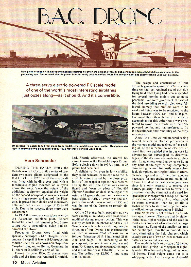
A three-servo electric-powered RC scale model of one of the world's most interesting airplanes just oozes along—as it should. And it's convertible.
Vern Schroeder
DURING THE EARLY 1930's the British Aircraft Corp. built a series of tandem two-place gliders designated as B.A.C. VII. In 1932 one of these aircraft was fitted with landing gear and with a motorcycle engine mounted on a pylon above the wing. Since the weight of the additional equipment equalled the weight of the second occupant, it was redesigned into a single-seater and named the Planette. It proved both docile and maneuverable; and had a speed range of 15 to 40 mph. Due to its success, three more were constructed.
In 1933 the company was taken over by the Australian sailplane pilot, Robert Kronfeld, who fitted the remaining No. 2 prototype with a streamlined pylon and re-named it the Drone.
Production Drones were fitted with specially developed 23-hp Douglas Sprite engines. In April 1936 one 1935 production model, G-AEUA, was flown non-stop from Croydon, England to Berlin, Germany, in 11 hours on 25 shillings worth of fuel. During the year 1936, 20 planes were built and the firm was renamed Kronfeld, Ltd. Shortly afterward, the aircraft became known as the Kronfeld Super Drone. Before closing down in 1937, a total of 28 planes had been built.
A delight to fly, even in low visibility, they could be heard for miles due to the incredible noise created by the close proximity of the propeller tips to the structure. During the war, one Drone was camouflaged and flown by pilots of No. 609 Fighter Squadron on duck-shooting sorties using a 12-gauge shotgun and a ring-and-bead sight. G-AEKV, which was the subject of our model, was rebuilt in 1950 and was the last of the Drones to remain airworthy.
Of the 28 planes built, probably no two were exactly alike. Many were crashed and modified during reconstruction. This was clearly evident in the photos of AEKV Bill Winter was able to furnish during the construction of our Drone. The specifications as listed in British Civil Aircraft are as follows: Wingspan 39 ft. 8 in.; length 21 ft. 2 in.; and height 7 ft. Depending on the powerplant, the maximum speed ranged from 70-73 mph, cruising speed 60-65 mph, and initial climb was 380-480 ft. per minute. The ceiling was 12,500 ft. and range 300-340 miles.
The design and construction of our Drone began in the spring of 1974; at which time we had just regained use of our club flying field after flying had been suspended for several months mainly due to noise problems. We were given back the use of the field providing several rules were followed, namely that mufflers were to be used and flying was to be restricted to the hours between 10:00 a.m. and 8:00 p.m. For most fliers these hours are perfectly acceptable; but this writer has always preferred to avoid the crowds with their 60-powered bombs, and has preferred to fly in the calmness and tranquility of the early morning air.
About this time we remembered seeing several articles on electric propulsion in various model magazines. After reading all of the information on electrics we could find, we decided that in our case its advantages far outweighed its disadvantages; so the decision was made to go electric. Its quietness would allow us to fly at any hour of the night or day, completely eliminating the need for costly, messy glow fuel, glow plugs, starting batteries, starters, cleaner, rags and all of the other goodies necessary for gas engine operation. In addition, it is ideal for pusher configurations since it is only necessary to reverse the battery polarity to the motor to reverse its direction; thereby eliminating the need for special pusher props which are quite limited in sizes and availability. Also, what could be more convenient than to just flip a switch or lever to start and stop the motor at will, either on the ground or in flight?
Electric power is not without its disadvantages, however. They are mainly higher initial cost and higher weight, and the need in most cases for a set of on-the-field charging batteries. Some of the smaller systems can be charged from an automobile battery, eliminating the field charger, which usually consists of two or three motorcycle batteries connected in series.
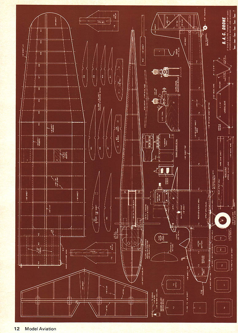
Our model is built to a scale of 2 inches equals 1 foot, giving a wingspan of slightly under 80 inches and a length of just over 42 inches. Total weight came out to a whopping 5 lb. 3 oz. using an Astro-10. electric power unit. A suggested glow-engine installation is shown for those not wishing to go the electric route. If you choose electric, however, keep all construction as light as practical, especially at the tail. Our model required 5 ounces of ballast at the nose to bring the CG to the proper location.
We suggest building the tail surfaces from 3/16" stock instead of 1/4", using 3/32" sides, and possibly substituting a wire tail skid for the steerable tail wheel. If all radio gear and the Astro-10 battery (follow motor manufacturer's instructions) is kept as far forward as possible, and a lightweight set of wheels, such as Trexler, used; it is likely that the five ounces of ballast could be eliminated and the total weight could be reduced as much as 12 to 14 ounces. Elimination of the motor on-off switch servo could save another couple of ounces; thereby possibly saving a total of 16 ounces, lowering the total weight from slightly over five pounds to four pounds. This would increase performance considerably.
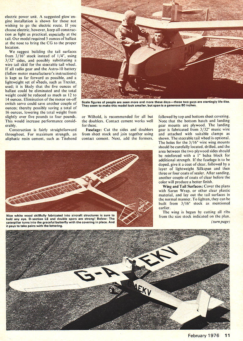
Construction is fairly straightforward throughout. For maximum strength, an aliphatic resin cement, such as Titebond or Wilhold, is recommended for all but the doublers. Contact cement works well for these.
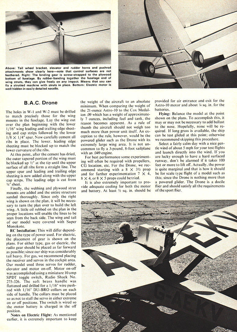
Fuselage:
Cut the sides and doublers from sheet stock and join together using contact cement. Next, add the formers, followed by top and bottom sheet covering. Note that the bottom hatch and landing gear mounts are plywood. The landing gear is fabricated from 3/32" music wire and attached with suitable clamps as shown. The steerable tail wheel is optional. The holes for the 3/16" wire wing mounts should be carefully located, drilled, and the area between the two plywood sides should be reinforced with a 1" balsa block for additional strength. If the fuselage is to be doped, give it a coat of clear, followed by a layer of lightweight Silkspan and then three or four coats of sealer. After sanding, another couple of coats of clear before the color will produce a better finish.
Wing and Tail Surfaces:
Cover the plans with Saran Wrap, or other clear plastic material, and lay out the tail surfaces in the normal manner. To lighten, they can be built from 3/16" stock as mentioned earlier.
The wing is begun by cutting all ribs from the size stock indicated on the plan.
B.A.C. Drone
Scale: 2 in = 1 ft. The holes in W-1 and W-2 must be drilled to match precisely those for the wing mounts in the fuselage. Lay the wing out over the plan beginning with the lower 1/16" wing leading and trailing edge sheeting and cap strips followed by the lower 1/8 x 1/4" spar. Now carefully cement all ribs in place. The lower, leading edge sheeting must be blocked up to match the lower curvature of the ribs.
At this point, after the cement has dried, the outer tapered portion of the wing must be blocked up 1/2" at the tip until the upper surface of all ribs form a straight line. The upper spar and leading and trailing edge sheeting is now added along with the upper cap strips. The leading edge is cut from 1/4" sheet.
Finally, the webbing and plywood strut mounts are added and the entire structure sanded thoroughly. Since only the right wing is shown on the plan, it will be necessary to turn the plan over to build the left wing. A little oil rubbed on the plan in the proper locations will enable the lines to be seen from the back side. The wing and tail of our model were covered with Super Monokote.
RC Installation:
This will differ depending on the type of power used. For electric, the placement of gear is shown on the plans. For either type, gas or electric, the radio gear should be placed as far forward as possible; since our ship was considerably tail heavy. For gas, we recommend placing the receiver and servos in the cockpit area. Our model used three servos for rudder, elevator and motor on-off. Motor on-off was accomplished using a miniature 10 amp SPDT toggle switch, Radio Shack No. 275-326. The soft brass handle was flattened and drilled for a 1/16" wire pushrod with 1/16" DU-BRO collars on each side of handle. The collars must be placed so as not to stall the servo in either extreme on or off positions. The switch is wired so the motor battery is charged in the off position.
Notes on Electric Flight:
As mentioned earlier, it is extremely important to keep the weight of the aircraft to an absolute minimum. When comparing the weight of the 21-ounce Astro-10 to the Cox Medallion .09 which has a weight of approximately 7 ounces, including fuel and tank, the reason becomes apparent. As a rule of thumb the aircraft should not weigh too much more than the power unit itself. An exception to the rule, however, would be the powered glider such as the Drone with its extremely large wing area. It is not uncommon to fly a 3-pound, 8-foot sailplane with a .049 engine.
For best performance some experimenting will often be required with propellers, CG location, etc. For the Drone, we recommend starting with an 8 x 3-1/2 prop and further experimentation 7 x 4, 8 x 4, or 8 x 5 props could be tried.
It is also extremely important to provide adequate cooling for both the motor and battery. At least 1/2 sq. in. should be provided for air entrance and exit for the Astro-10 motor and about 1/4 sq. in. for the batteries.
Flying:
Balance the model at the point shown on the plans. To accomplish this, it may or may not be necessary to add ballast to the nose. Hopefully, none will be required. If long grass is available, the ship can be test glided at this point; otherwise we recommend skipping this procedure.
Select a fairly calm day with a nice gentle wind of about 5 mph for your test flights and launch directly into the wind. If you are lucky enough to have a hard surfaced runway, don't be alarmed if it takes 100 feet or more to lift off. Actually, the power is quite marginal and that is how it should be for scale type flight of a model such as this; since the Drone is nothing more than a powered glider. The Drone is a docile flier and should satisfy all the requirements of the sport flier.
Transcribed from original scans by AI. Minor OCR errors may remain.

