
BACK TO BASICS
Leon Kincaid
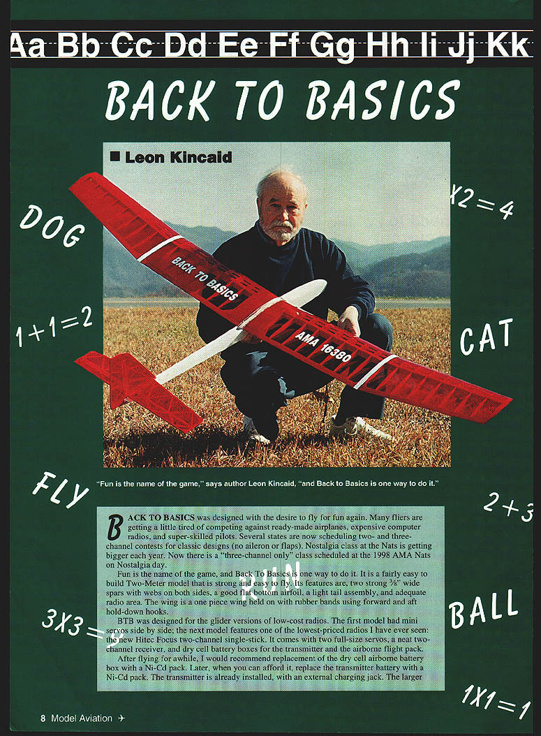
Back To Basics was designed with the desire to fly for fun again. Many fliers are getting a little tired of competing against ready-made airplanes, expensive computer radios, and super-skilled pilots. Several states are now scheduling two- and three-channel contests for classics (no aileron or flaps). Nostalgia class at the Nats is getting bigger each year. Now there is a "three-channel only" class scheduled at the 1998 AMA Nats on Nostalgia day.
Fun is the name of the game, and Back To Basics is one way to do it. It is a fairly easy-to-build two-meter model that is strong and easy to fly. Its features are two strong 3/8" wide spars with webs on both sides, a good flat-bottom airfoil, a light tail assembly, and adequate radio area. The wing is a one-piece wing held on with rubber bands using forward and aft hold-down hooks.
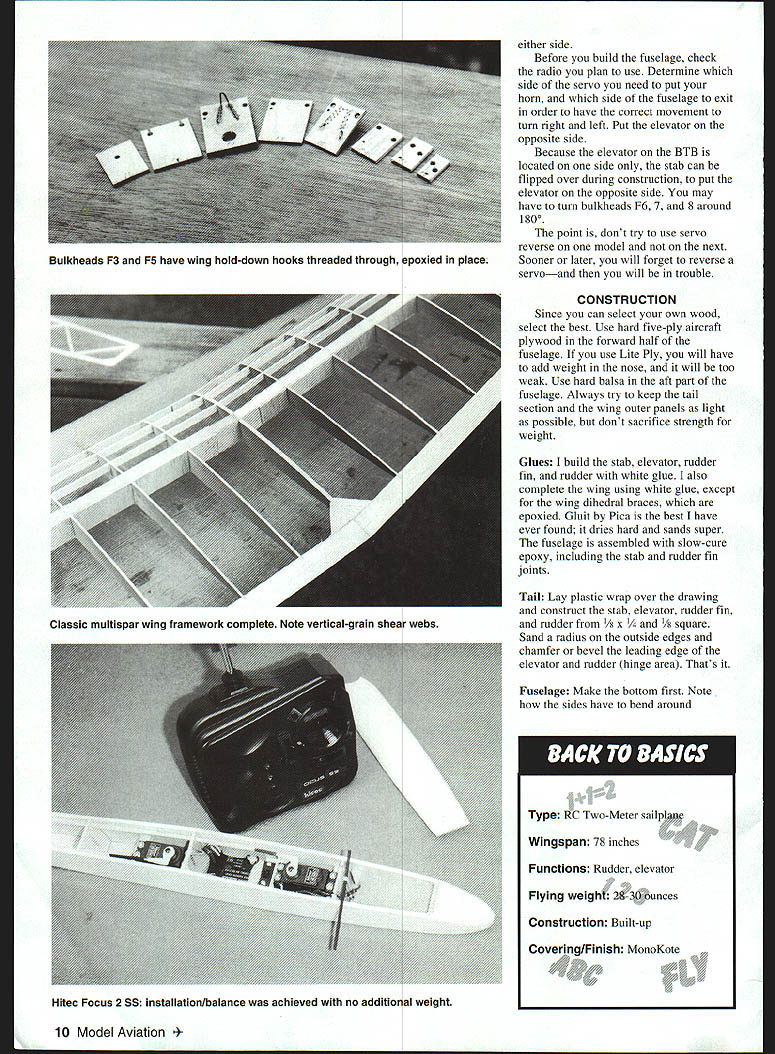
BTB was designed for the glider versions of low-cost radios. The first model had mini servos side by side; the next model features one of the lowest-priced radios I have ever seen: the new Hitec Focus two-channel single-stick. It comes with two full-size servos, a neat two-channel receiver, and dry cell battery boxes for the transmitter and the airborne high-pack.
After flying for a while, I would recommend replacement of the dry-cell airborne battery box with a Ni-Cd pack. Later, when you can afford it, replace the transmitter battery with a Ni-Cd pack. The transmitter is already set up with an external charging jack.
On model number two, I completed the fuselage, sat it on a pencil at the 2½-inch mark, and located the radio gear until everything balanced. The sequence is: battery pack, one full-size servo, switch and receiver in the forward section, and the second servo just behind bulkhead #3. With the wing added, the CG once again came out right on 33%. Both airplanes test-flew with no change in balance and no change in elevator trim.
About the CG: You may think that the CG is rather forward, but think about this. Most modern airfoils with undercamber have a mean camber between 42–45% and may trim with the CG as far aft as 38% — a difference of 4–7%. This airfoil has a mean camber at 35% and the standard CG is only 2% farther forward.
General notes
- Because the gears are usually thin or fairly weak on many microservos, I highly recommend using the Sullivan #580 carbon-fiber pushrods. They are extremely light, and with the lightweight rudder and elevator of BTB, your chances of stripping the gears are greatly reduced.
- All servos, receivers, transmitters, and combinations of each do not always rotate the servos in the same direction. For example, my Futaba servos rotate in the opposite direction to my Airtronics, JRs, and Hitecs. With one receiver, both rudder and elevator may be reversed; with a different receiver only one surface may be reversed.
- I know that most transmitters now have a servo-reverse feature, but try to standardize your setup without using it. Even if you have a model-select option on your transmitter, try to standardize up and down, and right and left to be the same on each model. You can run the pushrods down and out the same side of your fuselage or you can cross the pushrods at bulkhead F8 and exit the fuselage on the opposite side. Elevator is always "push" for up, and can exit the fuselage on the side you like best.
- Before you build the fuselage, check the radio you plan to use. Determine which side of the servo you need to put your horn, and which side of the fuselage to exit in order to have the correct movement to turn right and left. Put the elevator on the opposite side.
- Because the elevator on the BTB is located on one side only, the stab can be flipped over during construction to put the elevator on the opposite side. You may have to turn bulkheads F6, F7, and F8 around 180°.
- The point is, don't try to use servo reverse on one model and not on the next. Sooner or later, you will forget to reverse a servo—and then you will be in trouble.
CONSTRUCTION
Since you can select your own wood, select the best. Use hard five-ply aircraft plywood in the forward half of the fuselage. If you use Lite Ply, you will have to add weight in the nose, and it will be too weak. Use hard balsa in the aft part of the fuselage. Always try to keep the tail section and the wing outer panels as light as possible, but don't sacrifice strength for weight.
Glues
I build the stab, elevator, rudder fin, and rudder with white glue. I also complete the wing using white glue, except for the wing dihedral braces, which are epoxied. Glu-It by Pica is the best I have ever found; it dries hard and sands super. The fuselage is assembled with slow-cure epoxy, including the stab and rudder fin joints.
Tail
Lay plastic wrap over the drawing and construct the stab, elevator, rudder fin, and rudder from 1/8 x 1/4 and 1/8 square. Sand a radius on the outside edges and chamfer or bevel the leading edge of the elevator and rudder (hinge area). That's it.
Fuselage
Make the bottom first. Note how the sides have to bend around bulkhead #8 and then go parallel when clamping to the rudder fin post. Cut both sides and shape together. Since it is very difficult to cut out all parts from a blueprint and have everything fit perfectly, use the bottom and sides to determine the exact width and height of each bulkhead.
After all holes are drilled in the bulkheads, bend the wing hold-down hooks, install them in bulkheads F3 and F5, and sew on with needle and thread. Add epoxy over the thread. The hooks are just below the wing and make it easy to add the rubber bands and allow the wing to slide forward if you have a crash.
Drill and slot the pushrod exits in the rear of the fuselage sides. You can scoop or gouge excess wood away using a sharp piece of brass tubing.
Lay the bottom down and glue each bulkhead in place. Make sure that the front face of F3 and the back face of F5 are slightly more than nine inches apart.
Add both fuselage sides at the same time. Clamp at F3 through F8. Because you cannot add the rudder fin at this time, use a piece of 1/8 x 1/2 scrap wood, wrapped in plastic wrap, as a dummy rudder fin post between the sides; clamp in place.
Clamp the sides to bulkhead F1 and any place you may need it. This is why I use slow-cure epoxy; it gives you a lot of time to clamp everything in place. When dry, remove all clamps except the one holding the dummy rudder post. Add the nose block and rough out to shape. Add the pushrod outer housing and epoxy well at the fuselage exit. Also add the antenna tube and exit the bottom of the fuselage. When dry, cut off the excess outside the fuselage.
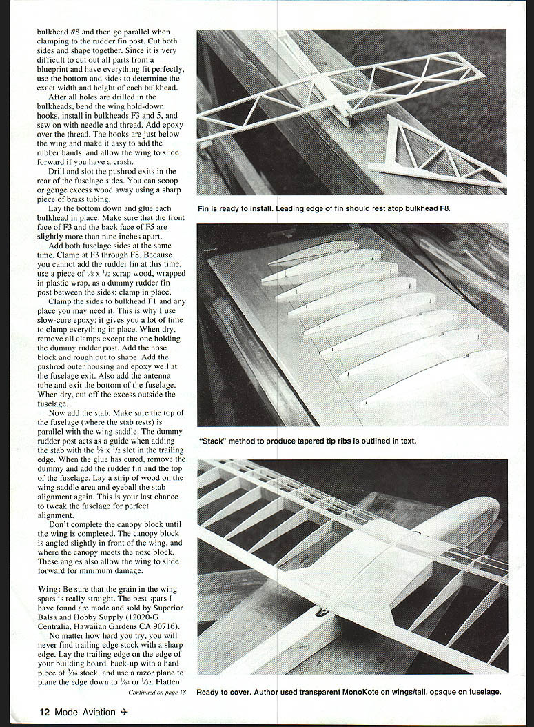
Now add the stab. Make sure the top of the fuselage (where the stab rests) is parallel with the wing saddle. The dummy rudder post acts as a guide when adding the stab with the 1/8 x 1/2 slot in the trailing edge. When the glue has cured, remove the dummy and add the rudder fin and the top of the fuselage. Lay a strip of wood on the wing saddle area and eyeball the stab alignment again. This is your last chance to tweak the fuselage for perfect alignment.
Don't complete the canopy block until the wing is completed. The canopy block is angled slightly in front of the wing and where the canopy meets the nose block. These angles also allow the wing to slide forward for minimum damage.
Wing
Be sure that the grain in the wing spars is really straight. The best spars I have found are made and sold by Superior Balsa and Hobby Supply (12020-C Centralia, Hawaiian Gardens CA 90716).
No matter how hard you try, you will never find trailing edge stock with a sharp edge. Lay the trailing edge on the edge of your building board, back up with a hard piece of 3/16 stock, and use a razor plane to plane the edge down to 1/8 or 3/32. Flatten with a coarse sanding block and finish with a finer block.
Make one basic rib template for ribs W4 through W12 from 1/16 plywood, but do not notch for spars, as this would make it difficult to use when cutting balsa ribs. The tapered ribs W12 through W19 are shown on the plans, but for me, cutting out these ribs from the drawing is time-consuming. I like to stack ribs between W11 and W19 and chop the tops off W12 through W18 quickly.
Using the plywood template, cut 28 ribs from 1/16 sheet and two from 1/8 sheet, plus a few extras. Cut three W19 tip ribs from the drawing and five W1 ribs from 1/8 sheet. Using one of the extra full-size ribs as a template, notch all ribs for the 3/8 spars only. Lay a piece of spar stock over the drawing for one tapered tip panel. Set a full-size rib over each rib on the drawing, mark, and cut to length at the leading and trailing edge. Remove shortened ribs and stack together on a short piece of spar stock. Take the extra W19 tip rib and mark the outside edge with a black felt-tip marker, and add to the stack. Mark an extra full-size rib and add to the stack in the W11 position. You should have a W11 and W19 with black around the outer edge, with W12 through W18 cut to length in the middle.
Cut the tops off W12–W18. If you tilt the ribs at an angle towards the tip, the top will come out more perpendicular with the sides. Cut and sand the tops till you touch the black edges of the W11 and W19 templates. Do the other wing panel, remove the templates and replace with proper ribs.
Now you must re-notch the tapered ribs for the 3/8 top spar. Using one of the extra full-size ribs as a template, notch all ribs W1 through W11 for the 1/16 x 1/4 turbulator spars. To notch the stacked tip ribs, mark a straight line between W11 and W19, then notch each rib as close to perpendicular to the outside edge as possible.
Cut all 3/8 spars, leading edge, and trailing edges to length. Notch the trailing edges for the ribs as shown; this is a must. Pin the leading and trailing edges to the plastic-wrap-covered drawing. Just lay the spar in place; do not put pins through the spars. Weight down if possible.
Glue and add ribs W4–W10 and W12–W19. To aid in getting the top spars the proper length, use the polyhedral template upside down at the end of each wing panel. Mark, cut, and add top spars. When dry, add 3/8"-wide sheet with horizontal grain between the spars at the polyhedral break and in the center section as shown on the drawing. This not only keeps the spars straight where there are no ribs, but aids in joining of panels and plywood braces.
Prop up each panel, sand the ends to the proper angle using the polyhedral template, and epoxy together. Add the plywood braces to the center and at the polyhedral break. Lay the center wing panels flat again and add the center bottom sheeting and ribs W1, W2, and W3. Cut and fit the 1/8" W11 ribs.
Install all turbulator spars and the top center sheeting. Add the 45° tip stock and contour the top to the shape of the airfoil. Add the triangular gussets, carve or plane the leading edge to shape, and sand as required. Last, glue the 1/32" plywood trailing edge support in place.
Final steps
Place the wing on the fuselage; contour and fit the canopy block between the wing and nose to fit properly. You will have to gouge a groove in the rear of the canopy to clear the rubber bands. Remove the wing and contour the canopy block, nose, and fuselage. Install the towhook nut plate or blind nut.
Final-sand everything, and cover the model. I recommend opaque MonoKote on the fuselage and transparent on the wings and tail section.
Hinge the elevator and rudder with 3M plastic repair tape. Use small Goldberg horns on the elevator and rudder. Install the longer-than-necessary pushrods.
Balance the model using the procedure described previously. However, balance a little tail-heavy and add a little weight to the nose.
A hint on balancing: a dry-cell battery box with four AA cells weighs about 110 grams; an AA 600 mA Ni-Cd weighs 95 grams; a 600 mA 2/3-A Ni-Cd pack is 85 grams; and a 270 mA pack weighs 55 grams.
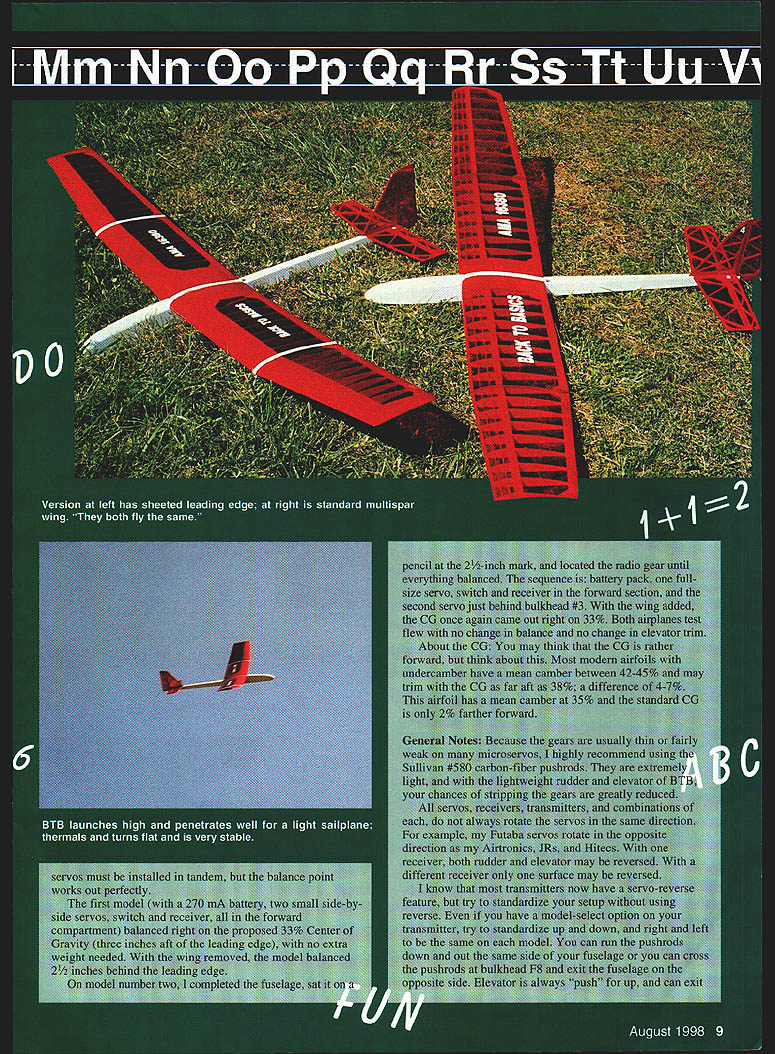
Washout: On one wing I have about 3/32" washout (gap under the tip of the trailing edge) and on the other wing I have almost nothing; both fly the same. But a little washout makes me feel better when slowing down.
Flying: My first model weighed 28 ounces ready to fly; model number two, with full-size servos and a sheeted leading edge, came out at 30 ounces. Both are light but penetrate well.
With the center of gravity and towhook located as shown on the plan, the launch is very steep and steady. Beginners may want to move the CG and towhook forward about 1/8 inch. If you move the CG aft, you will have to shim under the trailing edge or remove wood under the leading edge to lower the angle of incidence. Likewise, if you move the CG forward, you will have to add a shim under the leading edge, which will force the model to fly more slowly; you may have to add extra weight to penetrate the wind. The settings shown should give you many hours of pleasant flying.
A hint about airplanes with wings held on with rubber bands: if the wings are crooked after a hard landing, and you can straighten them without removing the rubber, the bands are too loose.
Add double-stick Scotch™ tape to the top side of your wing, down the center where the rubber bands cover. The tape will stick to the wing and the bands will stick to the tape. (Be sure the covering is well-ironed to the wood in this area.) You will be able to fly all day and never end up with a crooked wing. Even on a hard landing, the wing will straighten itself each time. The tape should last several flying sessions. When the stickiness is gone, add more tape over old. Later, you can peel or roll the old tape off and add new. It works!
Have fun.
Leon Kincaid Box 357 Webster NC 28788
- Type: RC Two-Meter sailplane
- Wingspan: 78 inches
- Functions: Rudder, elevator
- Flying weight: 28–30 ounces
- Construction: Built-up
- Covering/Finish: MonoKote
Transcribed from original scans by AI. Minor OCR errors may remain.

