

Balancing for Pitch
Chris Lella
Concluding a three-part series.
THE PITCH situation is by far the easiest of all three situations to trim for. In most cases, it's simply a matter of adding or taking away nose or tail weight. However, there's a scientific rule that says, in effect, that an advantage in some aspect will be accompanied by a disadvantage in another. This is also true here, because the pitch balance situation is probably the toughest to design and build for. This is because pitch is the only aspect of maneuverability that concerns us in CL flying. Unlike roll and yaw, we need moments sometimes and don't want them at others. One basic object concerned with roll and yaw, and that was to have zero moments around their respective axes at all times — we never want rolling and yawing. The pitch situation is compounded by two basic objects. We want pitch sometimes, and we don't want it at other times. First, we want balance when not pitching — when not maneuvering, like roll and yaw, there must be an ideal balance situation. Second, we want balance when pitching. There are basically two aspects of maneuvering — inside turns and outside turns. A stunt ship should turn both ways equally well.
Balance When not Pitching
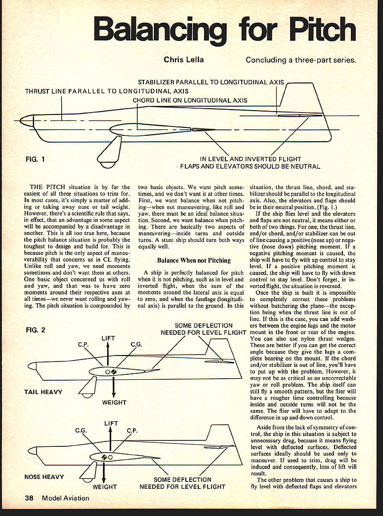
A ship is perfectly balanced for pitch when it is not pitching, such as in level and inverted flight, when the sum of the moments around the lateral axis is equal to zero, and when the fuselage (longitudinal axis) is parallel to the ground. In this situation, the thrust line, chord, and stabilizer should be parallel to the longitudinal axis. Also, the elevators and flaps should be in their neutral position. (Fig. 1)
If the ship flies level and the elevators and flaps are not neutral, it means either or both of two things. For one, the thrust line, and/or chord, and/or stabilizer can be out of line causing a positive (nose up) or negative (nose down) pitching moment. When a negative pitching moment is caused, the ship will have to fly with up control to stay level. If a positive pitching moment is caused, the ship will have to fly with down control to stay level. Don't forget, in inverted flight, the situation is reversed.
Once the ship is built it is impossible to completely correct these problems without butchering the plane — the exception being when the thrust line is out of line. If this is the case, you can add washers between the engine lugs and the motor mount in the front or rear of the engine. You can also use nylon thrust wedges. These are better if you can get the correct angle because they give the lugs a complete bearing on the mount. If the chord and/or stabilizer is out of line, you'll have to put up with the problem. However, it may not be as critical as an uncorrectable yaw or roll problem. The ship itself can still fly a smooth pattern, but the flier will have a rougher time controlling because inside and outside turns will not be the same. The flier will have to adapt to the difference in up and down control.
Aside from the lack of symmetry of control, the ship in this situation is subject to unnecessary drag, because it means flying level with deflected surfaces. Deflected surfaces ideally should be used only to maneuver. If used to trim, drag will be induced and consequently, loss of lift will result.
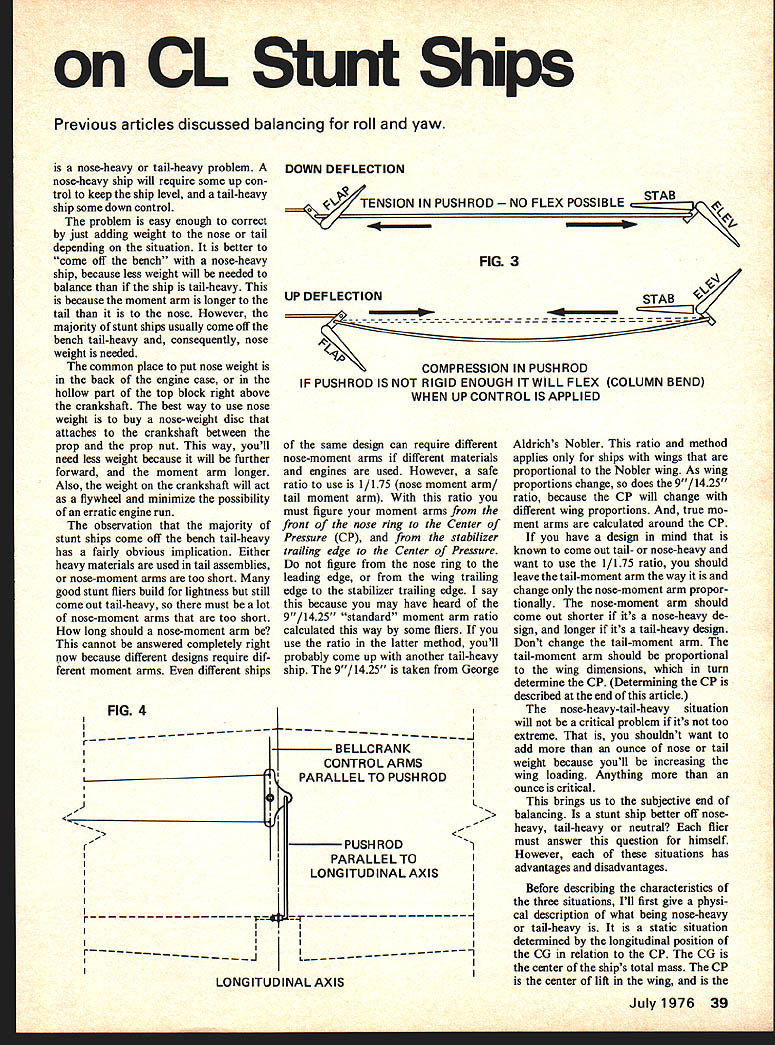
The other problem that causes a ship to fly level with deflected flaps and elevators is a nose-heavy or tail-heavy problem. A nose-heavy ship will require some up control to keep the ship level, and a tail-heavy ship some down control.
The problem is easy enough to correct by just adding weight to the nose or tail depending on the situation. It is better to "come off the bench" with a nose-heavy ship, because less weight will be needed to balance than if the ship is tail-heavy. This is because the moment arm is longer to the tail than it is to the nose. However, the majority of stunt ships usually come off the bench tail-heavy and, consequently, nose weight is needed.
The common place to put nose weight is in the back of the engine case, or in the hollow part of the top block right above the crankshaft. The best way to use nose weight is to buy a nose-weight disc that attaches to the crankshaft between the prop and the prop nut. This way, you'll need less weight because it will be further forward, and the moment arm longer. Also, the weight on the crankshaft will act as a flywheel and minimize the possibility of an erratic engine run.
The observation that the majority of stunt ships come off the bench tail-heavy has a fairly obvious implication. Either heavy materials are used in tail assemblies, or nose-moment arms are too short. Many good stunt fliers build for lightness but still come out tail-heavy, so there must be a lot of nose-moment arms that are too short. How long should a nose-moment arm be? This cannot be answered completely right now because different designs require different moment arms. Even different ships of the same design can require different nose-moment arms if different materials and engines are used. However, a safe ratio to use is 1/1.75 (nose moment arm/tail moment arm). With this ratio you must figure your moment arms from the front of the nose ring to the Center of Pressure (CP), and from the stabilizer trailing edge to the Center of Pressure. Do not figure from the nose ring to the leading edge, or from the wing trailing edge to the stabilizer trailing edge. I say this because you may have heard of the 9"/14.25" "standard" moment arm ratio calculated this way by some fliers. If you use the ratio in the latter method, you'll probably come up with another tail-heavy ship. The 9"/14.25" is taken from George Aldrich's Nobler. This ratio and method applies only for ships with wings that are proportional to the Nobler wing. As wing proportions change, so does the 9"/14.25" ratio, because the CP will change with different wing proportions. And, true moment arms are calculated around the CP.
If you have a design in mind that is known to come out tail- or nose-heavy and you want to use the 1/1.75 ratio, you should leave the tail-moment arm the way it is and change only the nose-moment arm proportionally. The nose-moment arm should come out shorter if it's a nose-heavy design, and longer if it's a tail-heavy design. Don't change the tail-moment arm. The tail-moment arm should be proportional to the wing dimensions, which in turn determine the CP. (Determining the CP is described at the end of this article.)
The nose-heavy/tail-heavy situation will not be a critical problem if it's not too extreme. That is, you shouldn't want to add more than an ounce of nose or tail weight because you'll be increasing the wing loading. Anything more than an ounce is critical.
This brings us to the subjective end of balancing. Is a stunt ship better off nose-heavy, tail-heavy or neutral? Each flier must answer this question for himself. However, each of these situations has advantages and disadvantages.
Before describing the characteristics of the three situations, I'll first give a physical description of what being nose-heavy or tail-heavy is. It is a static situation determined by the longitudinal position of the CG in relation to the CP. The CG is the center of the ship's total mass. The CP is the center of lift in the wing, and is the balance point on all stunt ships. When the CG is in front of the CP there is a nose-down moment, or nose-heaviness. When the CG is behind the CP there is a tail-down moment, or tail-heaviness (Fig. 2).
On most plans you'll see the CP labeled "Balance Point." On other plans you'll see it marked "CG," but this is not necessarily the CG. On others there is no label, just the symbol. Regardless, however it is labeled or marked, you'll usually see it at the high point of the airfoil at the back edge of the main spar. And should be intended to mean the CP balance point. This is not necessarily the correct position, because the CP varies with different wing dimensions. Knowing the CP is not critical when trimming for balance, because you trim according to the flying characteristics of the individual ship. However, it is necessary to know, when designing for balance, because it will determine how out of balance a ship may be.
I'll now describe the advantages and disadvantages of nose-heavy, tail-heavy, and neutrally-balanced ships.
Nose-heavy: Nose-heavy ships are most popular, because a nose-heavy ship is the most stable of the three. The reason is that a nose-heavy ship has its CG further forward, which means you have more surface area behind the CG. The more area there behind the CG, the more stable a ship will be. Therefore, a nose-heavy ship will groove the easiest. It will keep a straight path with the least amount of control necessary.
A disadvantage is that corners cannot be turned as quickly as with a tail-heavy ship. A lot of nose-heavy ships can turn tight corners, but it takes more control from the control surfaces and a quicker snap from the control handle. This means more stress on the wing, stabilizer, flaps, elevators and hinges. Because of this, nose-heavy ships will fatigue more readily than a tail-heavy ship.
Another disadvantage is that there will be less symmetry in the control of the ship, as opposed to the symmetry available in a neutrally-balanced ship. During inside loops for instance, you'll need much more up control at the bottom of the loop than at the top, and the loops will tend to sag to the ground.
Tail-heavy: The advantage of the tail-heavy situation was briefly mentioned. Corners can be turned tightly with ease. With a tail-heavy ship, you can almost think yourself into a corner, so the chance of jerking a corner is minimized. Also, the wing, stabilizer, flaps, elevators and hinges are much less stressed than with a nose-heavy ship.
Balance When Pitching
A ship has positive and negative pitch—inside and outside turning respectively. The ideal situation is to have symmetrical inside and outside control on these turns. That is, the sensitivity and stability of inside turns should equal that of outside turns. If more up control is needed on an inside turn than down control is needed on an outside turn, then there is not equal pitching balance. This is another added variable that the flier must adapt to.
The flier already has to adapt to the variables of weather conditions affecting engine runs, wind conditions affecting maneuvers at different points of the flying hemisphere, and changes in line tension at different attitudes in flight. Lack of symmetry between inside and outside turns only compounds these matters. Unlike them, it can be avoided. If it is, the pattern is much easier to fly. There are various reasons that can cause this. I'll start with the simplest and work toward the more complex. They are as follows:
- Thrust line, and/or chord, and/or stabilizer are out of line: This was mentioned in the section on balance when not pitching. If one or all of these are out of line, the ship will turn tighter in the direction that the moment caused by the misalignment is acting.
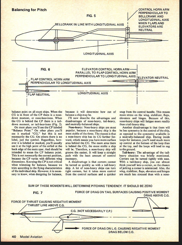
- Flexible pushrods: Because of the way that the standard control linkages for stunt flying is set up, we have tension in the pushrods for down control, and compression in the pushrods for up. When down control is applied, there can never be flex in the pushrods because the nature of tension does not allow it. When up control is applied, compression causes a tendency for the rods to flex. This is known as a "column bend." The longer, thinner, and less rigid a rod is, the less compression that is required to bend it. So, if a pushrod does not have enough of these characteristics to withstand the compression caused by up control, it will flex. Because of the flex, the ship will not be as sensitive to up control as it will be to down control, and consequently, the ship will turn outside maneuvers tighter than inside.
There are two solutions to this problem. One is to use a thick enough rod. A .035 size stunt ship will be fine with a 3/32" pushrod.
The other solution is to put bearings, where the pushrod has to go through, on the ship's bulkheads. Many plans indicate this, but I don't recommend it because it can hinder the smoothness of the controls with friction from the bearings. Some plans indicate three bearings on the bulkheads between the wing and the tail. If you have to use bearings, just use one on the bulkhead that is closest to the midway point between the wing and the tail.
Different lengths of the arms on the bellcrank that are connected to the up and down leadouts: If the arms on the bellcrank that the leadouts are connected to are different lengths, inside and outside turning will be different. Say, for instance, that the arm connected to the down leadout is shorter than the arm connected to the up leadout. Your ship will then be more sensitive to down control than to up.
Balancing for Pitch/Lella
because it will take less movement to utilize your necessary down. Consequently, with equal movement from the control handle, the ship will turn tighter outside maneuvers.
Unequal up and down movement of elevators and flaps: If the elevators and flaps do not deflect the same distance up and down, the ship will again turn unsymmetrically. This is caused by cockeyed assembly of the control linkage. Specifically, the alignment of the linkage should be as follows:
- The up and down arms on the bellcrank, which form a straight line, should be parallel to its connecting pushrod when the elevators and flaps are neutral. The arm should be parallel to the longitudinal axis. (Fig. 4)
- The plane of the bellcrank should be parallel to, or lie on, the longitudinal axis. (Fig. 5)
- The flap control horn arm should be perpendicular to the bellcrank and the longitudinal axis when the elevators and flaps are neutral. (Fig. 5)
- The elevator control horn arm should be parallel to the flap control horn arm. In other words, if the flap control horn arm is perpendicular to the flap, the elevator control horn arm should be perpendicular to the elevator. (Fig. 6)
Improper aerodynamical balance around the lateral axis: The vertical position of the thrust line and the surfaces causing drag are of concern here. In this series of articles, drag has yet to be mentioned as a cause of imbalance. It has only been alluded to as causing loss of lift. This is because the drag forces on a ship with respect to roll and yaw are for the most part symmetrical around their respective axes. (more) However, with respect to pitch, the drag forces around the lateral axis are not symmetrical, and along with thrust, they account for pitch moments around this axis.
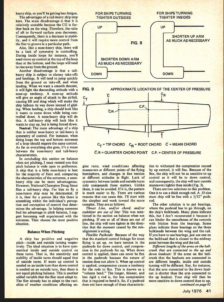
All of the external surface is exposed to drag and, if you look at a side view of almost any conventionally designed stunt ship, you'll see how the vertical positions of surfaces have no symmetry. The surfaces of main concern here are the tail section and landing gear. Most tail sections are located completely above the CG. This means the force of drag on that surface will also be above the CG, and will cause a positive (nose up) moment around the lateral axis. The landing gear is located below the CG. Consequently the force of drag here will be below the CG, and will cause a negative (nose down) moment around the lateral axis. The other force acting in conjunction with drag is thrust. Most stunt ships have their thrust line above the CG and this will also cause a negative moment around the CG. (Fig. 7.)
Ideally, all of these moments should balance out to zero. If they do, this aspect will not affect the inside-outside symmetry of turns. Besides, if they don't, and many times they don't, the ship will turn tighter in one direction.
When there is such a case, there is usually a resulting negative moment, and the ship turns outside better than inside. This means that the force of drag on the landing gear and the force of thrust are causing a greater moment than the drag on the tail surface, which acts opposite to the latter two forces. It would be proper right now to show how drag forces are calculated. But unfortunately, this would be quite lengthy and perhaps unintelligible to anyone but an engineer. However, I'll generalize the idea.
Since thrust (when the thrust line is above the CG) and drag on the landing gear account for a significant amount of negative moment, i.e., it is fitting that the tail surface must account for an equally opposing positive moment. The longer and more bulky the landing gear is, and the higher that the surface is above the CG, the higher the tail section must be. As long as your landing gear is not of a radical dimension, it is advisable to stick with a ratio of stabilizer height to thrust height above the CG. I suggest using a ratio of at least 2:1 for ships with a conventional vertical fin (vertical stab and rudder). Use at least 3:1 without a vertical fin. In other words, for a ship with a conventional vertical fin that has the thrust line 1/2" above the CG, the stab should be at least 1" above the CG, etc. A ratio cannot be used for ships with the thrust line right on the CG, so the stab should be at least 3/8" above the CG with a vertical fin and at least 1/2" above without a vertical fin. The latter dimensions are for .35 ships with wing area of 550-600 sq. in. Other sizes should be scaled proportionally.
In summarizing this section on balance when pitching, keep in mind that all these causes of imbalance can combine to cause lack of symmetry. However, the total of all these factors will yield just one symptom. When your ship is finished, you'll either have an easy tune-up — tighter outside, tighter inside, or a well balanced ship with respect to pitching symmetry. If your ship has an undesired symptom, it is obviously ridiculous to directly correct one of these causes because it requires digging into the ship. The only exception is a misaligned thrust line. There is one way, however, to correct lack of symmetry, regardless of the cause. You can compensate by changing the lengths of the arms on the control handle. The rule is this: shorten the arm of the control that turns tighter. If your ship turns tighter outside, shorten the down arm on the control handle and vice versa. Doing this gives opposite control moments compensating for unsymmetrical flying moments. (Fig. 8.)
Finding the Center of Pressure (CP)
The Center of Pressure is defined as the point in the wing where the resultant of all lift and drag forces on the wing act. This term is rarely used anymore by aerodynamicists because it cannot be used analytically with anything other than a symmetrical airfoil. I won't explain this because it is lengthy and does not directly concern us. Technically, it would be better to use the term center of lift, which is where the resultant of all lift forces act. We're interested in the center of lift for two reasons:
- It is the point through which all lift may be considered to act.
- It is the point at which pitching moments of the wing are referenced.
For most conventional wing sections and planforms, the aerodynamic center (the point about which pitching moment does not change appreciably with angle of attack) is near the quarter-chord point. The actual center of lift (or pressure) moves with angle of attack, but for our practical purposes in stunt ship design and trimming, using the quarter-chord as an approximation of the wing's aerodynamic center is satisfactory.
Pitch (continued)
to use the term "Aerodynamic Center." However, equations for finding this are much more complex, and for a symmetric airfoil, which is what we use in stunt, it would come out approximately the same as the Center of Pressure. So, since the term "Center of Pressure" is a bit more self-explanatory, and, since it can be used analytically with symmetrical airfoils, and also since its calculation is simpler, we will use it.
The Center of Pressure can be found by following these steps:
- Figure the Mean Chord. This is figured by averaging the Root Chord and Tip Chord. Say for instance that your Root Chord is 13" and your Tip Chord is 9". The Mean Chord would then be 11". Flaps are included in these values.
- Layout the planform of your wing on paper, and try to be accurate with dimensions.
- Draw in the Mean Chord of 11" where it is 11" on both wing panels.
- Figure the Quarter Chord Points for the Mean Chords. This would be 11" x 1/4 = 2.75". The Quarter Chord Points are 2.75" from the leading edge on the Mean Chords. Mark these points.
- Connect the Quarter Chord points with a straight line. The Center of Pressure is where this line crosses the center of the wing. (Fig. 9.)
The pitch situation has now been explained where balancing is concerned. However, you should acquaint yourself with particular dimensions of a ship which determine certain characteristics of pitch—mainly characteristics of turning capability. For a particular ship, it will turn tighter when tail-heavy than nose-heavy. But these are not the only things that affect a ship's turning radius. Longitudinal moment arms, wing aspect ratio, stab-elevator aspect ratio and area, wing taper, and prop gyration are other factors involved. I did not describe them because they do not affect pitch where balance is concerned, except for mention of moment arms which did concern the balance situation.
You may have noticed that throughout this series, the term "trim" was used sparingly. This was to dispel any ideas that balance is synonymous with trim. Trim is what we do to a ship to make it balanced. However, the complete balance situation is comprised of more than trimming. Good balance is better manifested in good design and construction, because trimming is compensation for our mistakes in design and construction. In the end, the well trimmed ship makes it. For some, what happens in the end is what counts. For others, it's how the end is reached, and therefore, even with a good end, they will have a certain lack of satisfaction in compensating for mistakes. This is why I spoke of good balance rather than good trim.
If anything is not understood, reread, and think it over. My address is 2850 E. 196 St., Bronx, N.Y. 10461—if you have questions.
Transcribed from original scans by AI. Minor OCR errors may remain.

