
Chris Lella
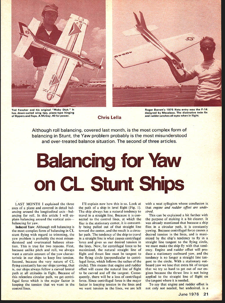
Although roll balancing, covered last month, is the most complex form of balancing in Stunt, the Yaw problem probably is the most misunderstood and over‑treated balance situation. The second of three articles.
Balancing for Yaw on CL Stunt Ships
LAST MONTH I explained the three axes of a plane and covered in detail balancing around the longitudinal axis—balancing for roll. In this article I will explain balancing around the vertical axis—balancing for yaw.
Induced Yaw: Although roll balancing is the most complex form of balancing in CL stunt flying with regard to trimming, the yaw problem is probably the most misunderstood and overtreated balance situation. This is true for two reasons. First, because unlike pitch and roll, we always want a certain amount of the yaw characteristic in our ships to keep line tension. Second, because the very nature of CL flying constantly has our ships yawing, that is, our ships always follow a curved lateral path at all attitudes in flight. Because of this relentless circular path, we get centrifugal force which is the major factor in keeping the tension that we want in the control lines.
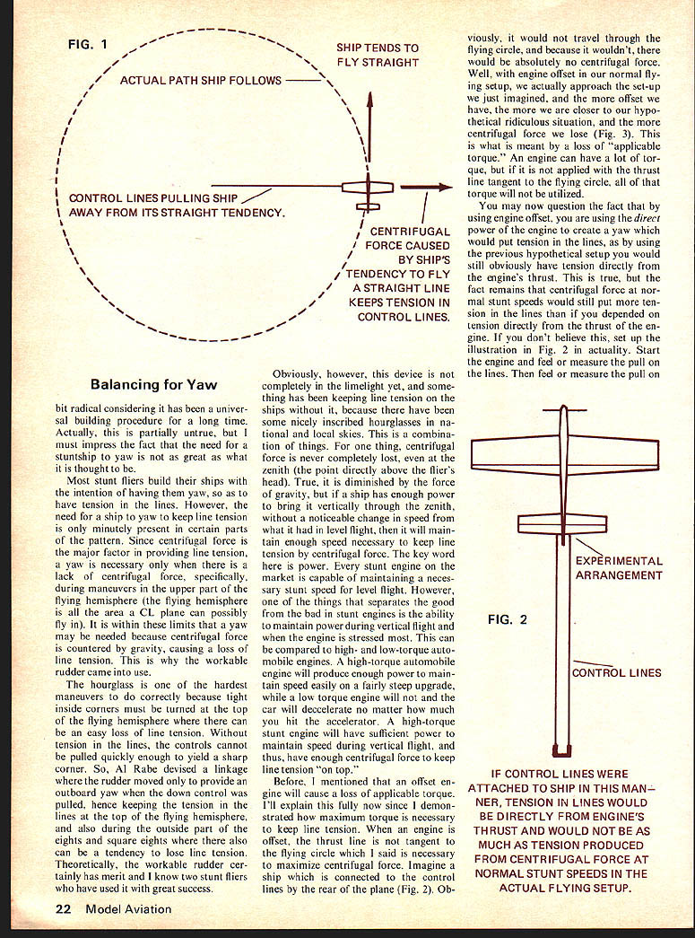
I'll explain now how this is so. Look at the path of a ship in level flight (Fig. 1). The ship always has a natural tendency to travel in a straight line. Because it is connected to the control lines, at which the flier is the stationary center, it is constantly being pulled out of that straight line toward the center, and the result is a circular path. The tendency of the ship to travel in a straight line is what causes centrifugal force and gives us our desired tension in the lines. Now, for centrifugal force to be maximized, the natural straight line of flight and thrust line must be tangent to the flying circle (perpendicular to centrifugal force, which follows the radius of the circle). This means that engine and rudder offset will cause the natural line of flight to be curved and off the tangent. Consequently, there will be a loss of centrifugal force. Since centrifugal force is the major factor in keeping tension in the lines and we want tension in the lines, we are left with a neat syllogism whose conclusion is that engine and rudder offsets are undesired.
This can be explained a bit further with the purpose of making it a bit clearer. It was already mentioned that because a ship flies in a circular path, it is constantly yawing. Because centrifugal force causes a desired tension in the lines, and is maximized by the ship's tendency to fly in a straight line tangent to the flying circle, we must make the ship fly with that tendency. Therefore, an engine and rudder offset will produce a stationary outboard yaw, and the tendency is no longer a straight line tangent to the circle. With a stationary outboard yaw we lose that extra bit of torque to curve the ship, and we end up with a ship that is harder to get out of our corners because the thrust line is not being applied to the straight line of flight on the tangent where it is needed.
To say that engine and rudder offset is not only not needed, but undesired, is a bit radical considering it has been a universal building procedure for a long time. Actually partially untrue. I must impress the fact that we need stuntship yaw greater than you might think. Most stunt fliers build ships with the intention of having yaw to keep line tension. However, we need ship yaw to keep line tension only in very minute parts of the pattern. Since centrifugal force is the major factor providing line tension, yaw is necessary only when centrifugal force is countered by gravity, causing loss of line tension. A workable rudder came into use for the hourglass—the hardest maneuvers—because tight inside corners must be turned at the top of the flying hemisphere, where we can easily lose line tension. Without tension lines, controls cannot be pulled quickly enough to yield a sharp corner. So Al Rabe devised a linkage where the rudder moved to provide outboard yaw when down control was pulled, hence keeping tension in the lines at the top of the hemisphere. Also, during the outside part of eights and square eights there can be a tendency to lose line tension. Theoretically a workable rudder certainly has merit; I know two stunt fliers who have used one with great success. Obviously, however, the device has not come into the limelight. Yet something has helped keep line tension in ships because we have some nicely inscribed hourglasses on national and local skies. A combination of things—the thing centrifugal force.
Balancing for Yaw
A bit radical considering it has been a universal building procedure for a long time. Actually, this is partially untrue, but I must impress the fact that the need for a stuntship to yaw is not as great as what it is thought to be.
Most stunt fliers build their ships with the intention of having them yaw, so as to have tension in the lines. However, the need for a ship to yaw to keep line tension is only minutely present in certain parts of the pattern. Since centrifugal force is the major factor in providing line tension, a yaw is necessary only when there is a lack of centrifugal force, specifically, during maneuvers in the upper part of the flying hemisphere (the flying hemisphere is all the area a CL plane can possibly fly in). It is within these limits that a yaw may be needed because centrifugal force is countered by gravity, causing a loss of line tension. This is why the workable rudder came into use.
The hourglass is one of the hardest maneuvers to do correctly because tight inside corners must be turned at the top of the flying hemisphere where there can be an easy loss of line tension. Without tension in the lines, the controls cannot be pulled quickly enough to yield a sharp corner. So, Al Rabe devised a linkage where the rudder moved only to provide an outboard yaw when the down control was pulled, hence keeping the tension in the lines at the top of the flying hemisphere, and also during the outside part of the eights and square eights where there also can be a tendency to lose line tension. Theoretically, the workable rudder certainly has merit and I know two stunt fliers who have used it with great success.
Obviously, however, this device is not completely in the limelight yet, and something has been keeping line tension on the ships without it, because there have been some nicely inscribed hourglasses in national and local skies. This is a combination of things. For one thing, centrifugal force is never completely lost, even at the zenith (the point directly above the flier's head). True, it is diminished by the force of gravity, but if a ship has enough power to bring it vertically through the zenith, without a noticeable change in speed from what it had in level flight, then it will maintain enough speed necessary to keep line tension by centrifugal force. The key word here is power. Every stunt engine on the market is capable of maintaining a necessary stunt speed for level flight. However, one of the things that separates the good from the bad in stunt engines is the ability to maintain power during vertical flight and when the engine is stressed most. This can be compared to high- and low-torque automobile engines. A high-torque automobile engine will produce enough power to maintain speed easily on a fairly steep upgrade, while a low-torque engine will not and the car will decelerate no matter how much you hit the accelerator. A high-torque stunt engine will have sufficient power to maintain speed during vertical flight, and thus have enough centrifugal force to keep line tension "on top."
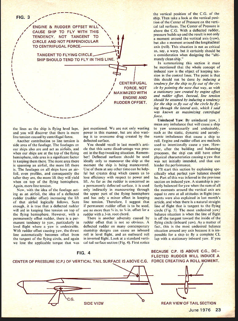
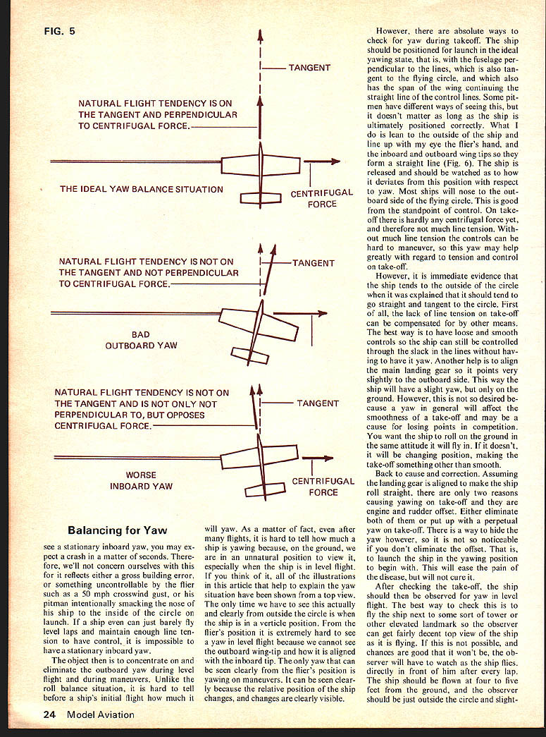
Before, I mentioned that an offset engine will cause a loss of applicable torque. I'll explain this fully now since I demonstrated how maximum torque is necessary to keep line tension. When an engine is offset, the thrust line is not tangent to the flying circle which I said is necessary to maximize centrifugal force. Imagine a ship which is connected to the control lines by the rear of the plane (Fig. 2). Obviously, it would not travel through the flying circle, and because it wouldn't, there would be absolutely no centrifugal force. Well, with engine offset in our normal flying setup, we actually approach the set-up we just imagined, and the more offset we have, the more we are closer to our hypothetical ridiculous situation, and the more centrifugal force we lose (Fig. 3). This is what is meant by a loss of "applicable torque." An engine can have a lot of torque, but if it is not applied with the thrust line tangent to the flying circle, all of that torque will not be utilized.
You may now question the fact that by using engine offset, you are using the direct power of the engine to create a yaw which would put tension in the lines, as by using the previous hypothetical setup you would still obviously have tension directly from the engine's thrust. This is true, but the fact remains that centrifugal force at normal stunt speeds would still put more tension in the lines than if you depended on tension directly from the thrust of the engine. If you don't believe this, set up the illustration in Fig. 2 in actuality. Start the engine and feel or measure the pull on the lines. Then feel or measure the pull on the lines. the lines as the ship is flying level laps, and you will discover that there is more line tension caused by centrifugal force just mentioned. We are not only wasting power in this manner, but are also wasting it to overcome drag created by the deflected surface.
Another contribution to line tension is side area of the fuselage. The fuselages on our ships are also arced and act as airfoils, and when our ships are at the top of the flying hemisphere, side area is a significant factor in keeping them there. The more area there is spanning an airfoil, the more lift there is. The fuselages on all ships have an airfoil, even profiles, and consequently the taller they are, the more lift they will yield when on top of the flying hemisphere. Again, more line tension.
Now, with the idea of the fuselage acting as an airfoil, the idea of a deflected rudder (rudder offset) increasing the lift of that airfoil logically follows. Sure enough, it is true that a deflected rudder will aid in keeping line tension on top of the flying hemisphere. However, with a permanently offset rudder, there is a permanent tendency to yaw, particularly in level flight where a yaw is undesirable. With rudder offset causing yaw, the thrust line automatically becomes offset from the tangent of the flying circle, and again we lose the applicable torque that was just mentioned.
We are not only wasting power in this manner, but are also wasting it to overcome drag created by the deflected surface.
Take a look at the vertical position of the C.G. of the ship. Then take a look at the vertical position of the Center of Pressure on the vertical tail surfaces. The Center of Pressure is above the C.G. With a deflected rudder, pressure builds up and the result is not only a moment around the vertical axis (yaw), but also a moment around the longitudinal axis (roll). This situation is not as critical as, say, a warp, but it certainly should be a consideration when designing the "ultimately clean ship."
In summarizing this section it must be mentioned that the whole concept of induced yaw is the object of keeping tension in the control lines. The point is that this should not be done by inducing a tendency for the ship to fly out of the circle by pointing the nose that way, as with a stationary yaw created by engine offset and rudder offset. Instead, line tension should be attained by inducing a tendency for the ship to fly out of the circle by flying through the lateral axis, which I said was known as maximizing centrifugal force.
Uninduced Yaw: By uninduced yaw, I mean any imbalance that will cause a ship to yaw unnecessarily and undesirably, such as the static, dynamic and aerodynamic imbalances that cause a ship to roll. Engine and rudder offset are methods used to intentionally cause a yaw. However, after the building and balancing processes, the ship can still have other physical characteristics causing a yaw that was not initially intended, and that can hinder the performance.
I'll start this section by explaining specifically what perfect yaw balance should be. Part of this was inferred in the previous section on induced yaw. A stunt ship is perfectly balanced for yaw when the sum of all the moments around the vertical axis are equal to zero at all attitudes in flight (moments were also explained in last month's article, and when there is a neutral straight line of flight that is tangent to the flying circle (Fig. 5). The most undesired yaw/balance situation is when the line of flight is off the tangent toward the inside of the flying circle (inboard yaw). As a matter of fact, this is the most undesired balance situation around any axis because it is impossible for a ship to fly a complete CL lap with a stationary inboard yaw. If you
Balancing for Yaw
see a stationary inboard yaw, you may expect a crash in a matter of seconds. Therefore, we'll not concern ourselves with this or if reflects either a gross building error, or something uncontrollable by the flier such as a 50 mph crosswind gust, or his bitman intentionally smacking the nose of his ship to the inside of the circle on launch. If a ship even can just barely fly level laps and maintain enough line tension to have control, it is impossible to have a stationary inboard yaw.
The object then is to concentrate on and eliminate the outboard yaw during level flight and during maneuvers. Unlike the roll balance situation, it is hard to tell before a ship's initial flight how much it will yaw. As a matter of fact, even after many flights, it is hard to tell how much a ship is yawing because, on the ground, we are in an unnatural position to view it, especially when the ship is in level flight. If you think of it, all of the illustrations in this article that help to explain the yaw situation have been shown from a top view. The only time we have to see this actually and clearly from outside the circle is when the ship is in a vertical position. From the flier's position it is extremely hard to see a yaw in level flight because we cannot see the outboard wing-tip and how it is aligned with the inboard tip. The only yaw that can be seen clearly from the flier's position is yawing on maneuvers. It can be seen clearly because the relative position of the ship changes, and changes are clearly visible.
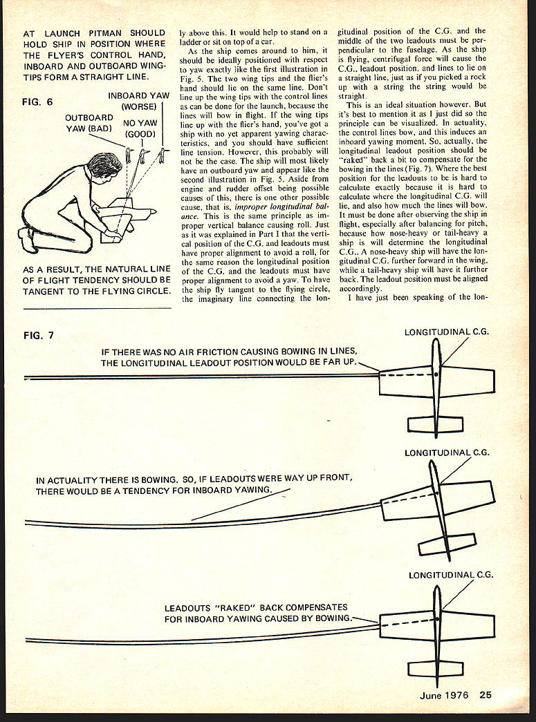
However, there are absolute ways to check for yaw during takeoff. The ship should be positioned for launch in the ideal yawing state, that is, with the fuselage perpendicular to the lines, which is also tangent to the flying circle, and which also has the span of the wing continuing the straight line of the control lines. Some pit-men have different ways of seeing this, but it doesn't matter as long as the ship is ultimately positioned correctly. What I do is lean to the outside of the ship and line up with my eye the flier's hand, and the inboard and outboard wing tips so they form a straight line (Fig. 6). The ship is released and should be watched as to how it deviates from this position with respect to yaw. Most ships will nose to the outboard side of the flying circle. This is good from the standpoint of control. On takeoff there is hardly any centrifugal force yet, and therefore not much line tension. Without much line tension the controls can be hard to maneuver, so this yaw may help greatly with regard to tension and control on take-off.
However, it is immediate evidence that the ship tends to the outside of the circle when it was explained that it should tend to go straight and tangent to the circle. First of all, the lack of line tension on take-off can be compensated for by other means. The best way is to have loose and smooth controls so the ship can still be controlled through the slack in the lines without having to have it yaw. Another help is to align the main landing gear so it points very slightly to the outboard side. This way the ship will have a slight yaw, but only on the ground. However, this is not so desired because a yaw in general will affect the smoothness of a take-off and may be a cause for losing points in competition. You want the ship to roll on the ground in the same attitude it will fly in. If it doesn't, it will be changing position, making the take-off something other than smooth.
Back to cause and correction. Assuming the landing gear is aligned to make the ship roll straight, there are only two reasons causing yawing on take-off and they are engine and rudder offset. Either eliminate both of them or put up with a perpetual yaw on take-off. There is a way to hide the yaw however, so it is not so noticeable if you don't eliminate the offset. That is, to launch the ship in the yawing position to begin with. This will ease the pain of the disease, but will not cure it.
After checking the take-off, the ship should then be checked for yaw in level flight. The best way to check this is to fly the ship next to some sort of tower or other elevated landmark so the observer can get fairly decent top view of the ship as it is flying. If this is not possible, and chances are good that it won't be, the observer will have to watch as the ship flies directly in front of him after every lap. The ship should be flown at four to five feet from the ground, and the observer should be just outside the circle and slightly above the flier. It would help to stand on a ladder or sit on top of a car.
As the ship comes around to him, it should be ideally positioned with respect to yaw exactly like the first illustration in Fig. 5. The two wing tips and the flier's hand should lie on the same line. Don't line up the wing tips with the control lines as can be done for the launch, because the lines will bow in flight. If the wing tips line up with the flier's hand, you've got a ship with no yet apparent yawing characteristics, and you should have sufficient line tension. However, this probably will not be the case. The ship will most likely have an outboard yaw and appear like the second illustration in Fig. 5. Aside from engine and rudder offset being possible causes of this, there is one other possible cause, that is, improper longitudinal balance. This is the same principle as improper vertical balance causing roll. Just as was explained in Part I that the vertical position of the C.G. and leadouts must have proper alignment to avoid a roll, for the same reason the longitudinal position of the C.G. and the leadouts must have proper alignment to avoid a yaw. To have the ship fly tangent to the flying circle, the imaginary line connecting the longitudinal position of the C.G. and the middle of the two leadouts must be perpendicular to the fuselage. As the ship is flying, centrifugal force will cause the C.G., leadout position, and lines to lie on a straight line, just as if you picked a rock up with a string, the string would be straight.
This is an ideal situation however. But it's best to mention it as I just did so the principle can be visualized. In actuality, the control lines bow, and this induces an inboard yawing moment. So, actually, the longitudinal leadout position should be "raked" back a bit to compensate for the bowing in the lines (Fig. 7). Where the best position for the leadouts to be is hard to calculate exactly because it is hard to calculate where the longitudinal C.G. will lie, and also how much the lines will bow. It must be done after observing the ship in flight, especially after balancing for pitch, because how nose-heavy or tail-heavy a ship is will determine the longitudinal C.G. A nose-heavy ship will have the longitudinal C.G. further forward in the wing, while a tail-heavy ship will have it further back. The leadout position must be aligned accordingly.
IF THERE WAS NO AIR FRICTION CAUSING BOWING IN LINES, THE LONGITUDINAL LEADOUT POSITION WOULD BE FAR UP.
IN ACTUALITY THERE IS BOWING. SO, IF LEADOUTS WERE WAY UP FRONT, THERE WOULD BE A TENDENCY FOR INBOARD YAWING.
LEADOUTS "RAKED" BACK COMPENSATES FOR INBOARD YAWING CAUSED BY BOWING.
Balancing for Yaw
Longitudinal alignment of the leadout position after the stunt ship has been flown. This would be quite annoying if the leadouts were permanently secured. However, we still see a lot of this, and I can't help but think that, because of it, many stunt ships are flying unbalanced. The adjustable leadout guide came into existence in the early Sixties, and surely it was a helpful little invention. Just as the chances are great that a stunt ship cannot be well balanced in every aspect on the bench, the chances are the same that a stunt ship can never be well balanced without adjustable leadouts. I also think that they are easier to make and install than permanent leadouts. Several of the latest ships have them illustrated on their plans. If you don't know how to make them yet, I suggest taking a look at them and incorporating them into your building procedure. You'll find them on the plans for my ship Sundance, and also on the plans for the Stunt Machine, Genesis, and Sunshine, to mention a few.
After the yaw/balance situation in level flight is treated, we are left with the perpetual problem of yawing that occurs only during maneuvers. Yawing during maneuvers happens usually on corners where a control is pulled, and it disappears right after the controls are neutralized. This can be caused by three reasons:
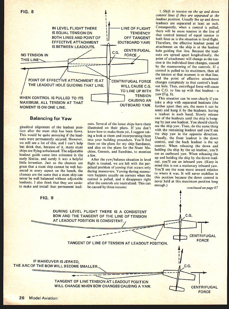
- Shift in tension on the up and down control lines if they are separated at the leadout position. Usually the up and down leadouts are separated at least an inch. Consequently, when a control is pulled, there will be more tension in the line of that control instead of equal tension in both lines as is the situation in level flight. Therefore, the effective leadout point of attachment on the ship is at the leadout hole guiding that line. Because the leadouts are spread apart longitudinally, the point of attachment will change as the tension in the individual lines changes, caused by the maneuvers of the controls. If a control is pulled to its maximum, then all the tension at that moment is on that line and the point of effective attachment changes completely to that control's leadout hole. Then, centrifugal force will cause the C.G. to line up with that leadout — a yaw (Fig. 8).
This situation can be seen clearly if you take a ship with separated leadouts and hang it by the leadouts (the further apart they are, the more it can be seen) and hang it by the leadouts, having a leadout in each hand. Slowly release one of the leadouts until the ship is hanging by just one leadout. You should clearly see the ship yaw. Then, do the same thing with the remaining leadout and you'll see the ship yaw in the opposite direction. Usually, the front leadout is the down control, and the back leadout is the up control. When releasing the down and holding the ship by the up leadout, you'll see an outboard yaw. When releasing the up and holding the ship by the down leadout, you'll see an inboard yaw. (Keep in mind this is not a stationary inboard yaw. You'll see the nose move inward relative to where it was. It will never stabilize in this position because the down control is never held at this maximum position long enough.) In retrospect now, this inboard yawing moment induced by pulling the down control is a cause for many ships to have a tendency to lose line tension at the start of outside maneuvers, particularly sharp corners. Think back to that hourglass now, and consider what you're up against, not only with a loss of speed, but also with an inboard yaw compounding things when you're on top of the flying hemisphere popping that down control.
There is a simple solution to this, although Bill Simmons is the only one I've seen do it. The problem is simply resolved by positioning the up and down leadout holes together so there is no longitudinal separation. Just leave about 1/32 in. to 1/16 in. between leadout holes so the leadouts won't twist inside the ship.
- Change in the bow of the lines during flight. Before, it was mentioned that a ship would have a tendency to yaw to the inboard side caused by the bow in the lines. I'll explain this a bit further now. As explained, the longitudinal C.G. will line up with the lines at the leadouts. With a bow, the tension in the lines is not straight but curves with the lines. That curve, however, stops at the leadouts, and the tension from there on into the ship is straight and tangent to the bow at the point of the leadouts. When we aligned the leadouts before to compensate for the bow, we were talking about a consistent bow for level flight. But, during maneuvers the bow changes. It becomes less at some points, and more at others. Therefore, the direction of the tension at the point of the leadouts will also change, and the longitudinal C.G. will tend to line up again with that tension. Hence, again there will be yawing (Fig. 9).
There is no way to eliminate this problem because there will always be a change in tension and bowing in the lines. However, it can be minimized, but only by smooth control at the stick. Any unnecessary jerking of the controls will cause yawing. You can also prove this while flying the ship in level flight. As it is flying level, jerk the handle back and forth without maneuvering the controls. Keep an eye on the ship and also have someone outside the circle watch closely. The motions of the ship should be easily seen to be yawing. Jerking the handle around will also make the ship's nose move. Some fliers actually do this when banging a corner. Even a simple maneuver must be popped, (and to get this close to a "rule book" corner) it should be done with a quick but smooth pivot of the wrist, not the arm. As tension in the lines decreases, we should follow that decrease and not fight it. In other words, ease into the tension, toward the ship, so it cannot build up too radically. With a decrease in tension, ease away from the ship so it cannot decrease too radically.
A good example is in a wingover. When the maneuver is first popped from level flight, the arm should be straight. As the ship comes overhead, the arm should be bending, compensating for the loss in tension as the ship goes through the top of the flying hemisphere. As the ship is on its descent, the arm should be straightening out, following the increase in tension.
Yaw (continued)
the pullout, pivot the control handle. Don't pull it. And, simultaneously lean a bit into the turn to ease the line tension, because at this point there is more line tension than at any other point in the pattern.
SHIP IN VERTICAL FLIGHT
FIG. 10
ACTUAL FLIGHT PATH
TANGENT TO FLIGHT PATH
NATURAL FLIGHT TENDENCY (OFF TANGENT YAW)
EXCESSIVE TIP WEIGHT CAUSING YAW IN VERTICAL FLIGHT
and consequently, there is the greatest tendency for outboard yawing caused by the changing bow in the lines. Remember: Uniform line tension is one of the best assets a stunt flier can have. With it a ship can, and usually will, fly well because it is an integral part of the ideal balance situation.
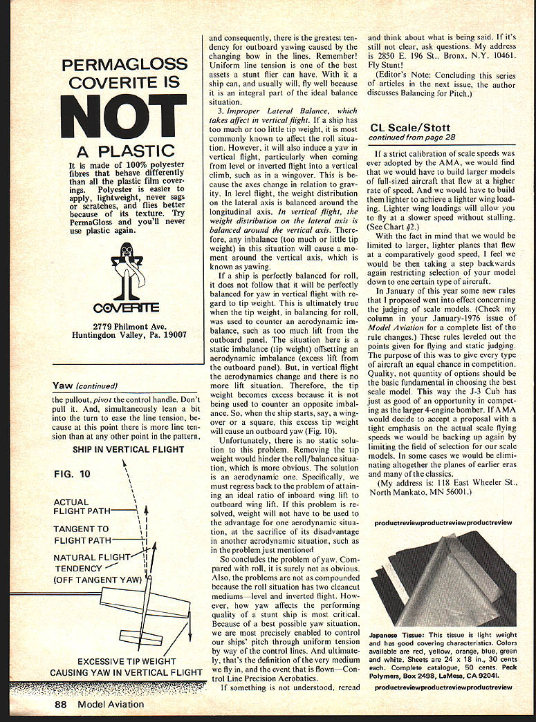
- Improper Lateral Balance, which takes effect in vertical flight. If a ship has too much or too little tip weight, it is most commonly known to affect the roll situation. However, it will also induce a yaw in vertical flight, particularly when coming from level or inverted flight into a vertical climb, such as in a wingover. This is because the axes change in relation to gravity. In level flight, the weight distribution on the lateral axis is balanced around the longitudinal axis. In vertical flight, the weight distribution on the lateral axis is balanced around the vertical axis. Therefore, any imbalance (too much or too little tip weight) in this situation will cause a moment around the vertical axis, which is known as yawing.
If a ship is perfectly balanced for roll, it does not follow that it will be perfectly balanced for yaw in vertical flight with regard to tip weight. This is ultimately true when the tip weight, in balancing for roll, was used to counter an aerodynamic imbalance, such as too much lift from the outboard panel. The situation here is a static imbalance (tip weight) offsetting an aerodynamic imbalance (excess lift from the outboard panel). But, in vertical flight the aerodynamics change and there is no more lift to offset the static imbalance. Therefore, the tip weight becomes excess because it is being used to counter an opposite imbalance. So, when the ship starts, say, a wingover or a square, this excess tip weight will cause an outboard yaw (Fig. 10).
Unfortunately, there is no static solution to this problem. Removing the tip weight would hinder the roll/balance situation, which is more obvious. The solution is an aerodynamic one. Specifically, we must regress back to the problem of attaining an ideal ratio of inboard wing lift to outboard wing lift. If this problem is resolved, weight will not have to be used to the advantage for one aerodynamic situation, at the sacrifice of its disadvantage in another aerodynamic situation, such as in the problem just mentioned.
So concludes the problem of yaw. Compared with roll, it is surely not as obvious. Also, the problems are not as compounded because the roll situation has two clean-cut mediums — level and inverted flight. However, how yaw affects the performing quality of a stunt ship is most critical. Because of a best possible yaw situation, we are most precisely enabled to control our ships' pitch through uniform tension by way of the control lines. And ultimately, that's the definition of the very medium we fly in, and the event that is flown — Control Line Precision Aerobatics.
If something is not understood, reread and think about what is being said. If it's still not clear, ask questions. My address is 2850 E. 196 St., Bronx, N.Y. 10461. Fly Stunt!
(Editor's Note: Concluding this series of articles in the next issue, the author discusses Balancing for Pitch.)
Transcribed from original scans by AI. Minor OCR errors may remain.

