
Band-Sawn Aluminum Engine Mounts
By L. F. Randolph
Custom-made engine mounts are almost non-existent in this hobby because their cost would usually exceed the value of the engines they support. However, if you have (or have access to) a band saw, it is simple and inexpensive to make an aluminum engine mount that is just right for a particular engine and airplane.
Start by looking in the yellow pages for an aluminum supplier near you (Reynolds, Alcoa, etc.) and check their remnant barrel. You will be looking for bar stock of either 2024-T4 or 6061-T6. The size of your engine determines the stock size: 1 1/2 by 2 1/2 by 2 1/2 inches is the minimum for a .60-size engine, and 1 1/4 by 1 1/4 by 2 inches is fine for a .25 and smaller. The pictures tell the rest of the story.
Procedure
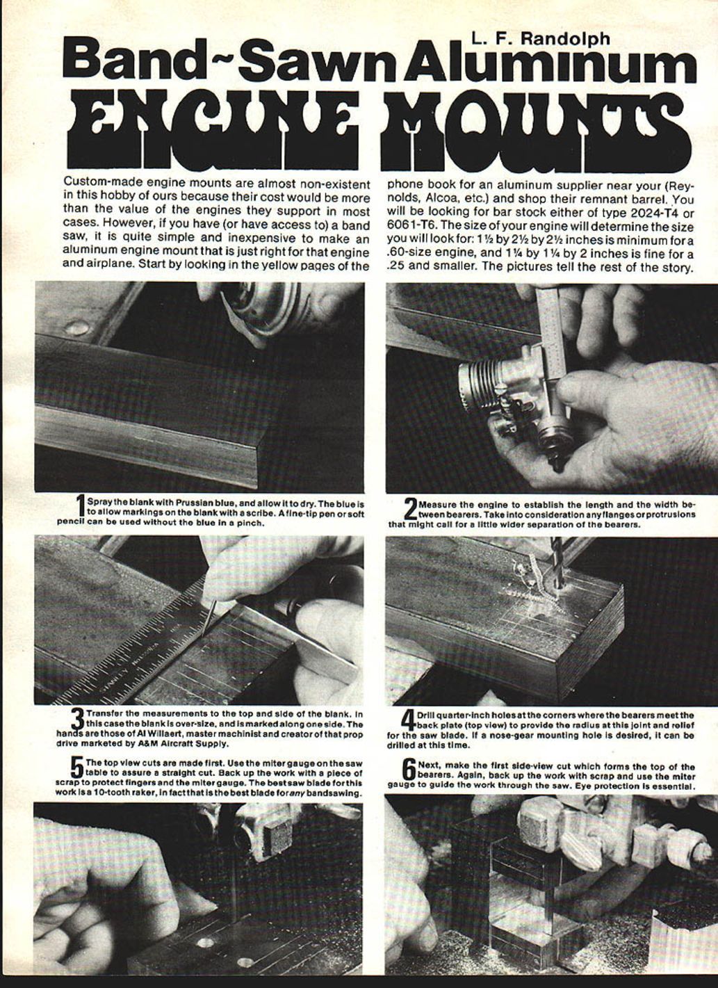
- Spray the blank with Prussian blue and allow it to dry. The blue helps make scribe markings visible. A fine-tip pen or soft pencil can be used without the blue in a pinch.
- Measure the engine to establish the length and the width between bearers. Take into account any flanges or protrusions that might require a slightly wider bearer separation.
- Transfer the measurements to the top and side of the blank. In this case the blank is oversize and is marked along one side. (The hands shown are those of Al Williard, master machinist and creator of that prop drive marketed by A&M Aircraft Supply.)
- Drill 1/4-inch holes at the corners where the bearers meet the back plate (top view) to provide the radius at this joint and relief for the saw blade. If a nose-gear mounting hole is desired, drill it at this time.
- Make the top-view cuts first. Use the miter gauge on the saw table to assure a straight cut. Back up the work with a piece of scrap to protect fingers and the miter gauge. The best saw blade for this work is a 10-tooth raker; in fact, that is the best blade for any bandsawing.
- Next, make the first side-view cut which forms the top of the bearers. Again, back up the work with scrap and use the miter gauge to guide the work through the saw. Eye protection is essential.
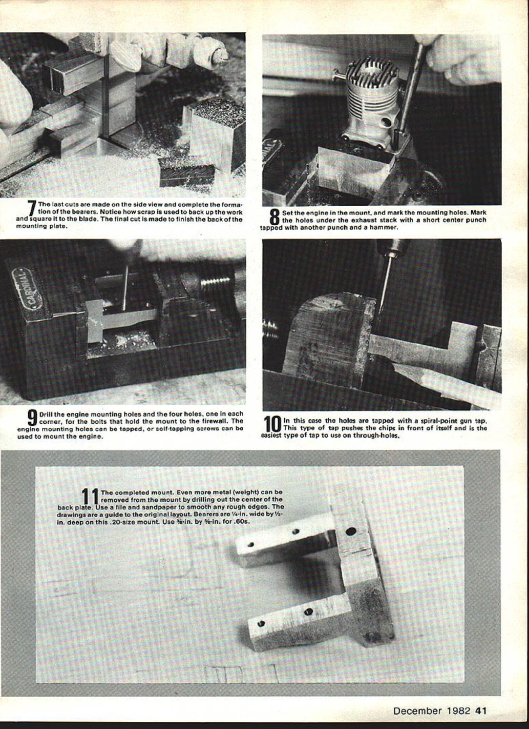
- Make the last cuts on the side view to complete the formation of the bearers. Use scrap to back up the work and square it to the blade. The final cut finishes the back of the mounting plate.
- Set the engine in the mount and mark the mounting holes. Mark the holes under the exhaust stack with a short center punch tapped with another punch and a hammer.
- Drill the engine mounting holes and the four holes (one in each corner) for the bolts that hold the mount to the firewall. The engine mounting holes can be tapped, or self-tapping screws can be used to mount the engine.
- In this case the holes are tapped with a spiral-point gun tap. This type of tap pushes the chips in front of itself and is the easiest type of tap to use on through-holes.
- The completed mount. Even more metal (and weight) can be removed by drilling out the center of the back plate. Use a file and sandpaper to smooth any rough edges.
Final Notes
The drawings are a guide to the original layout. Bearers on this .20-size mount are 1/4 inch wide by 1/4 inch deep. Use 3/8 inch by 5/8 inch for .60-size engines.
Transcribed from original scans by AI. Minor OCR errors may remain.

