
BARECAT
Bob Baron
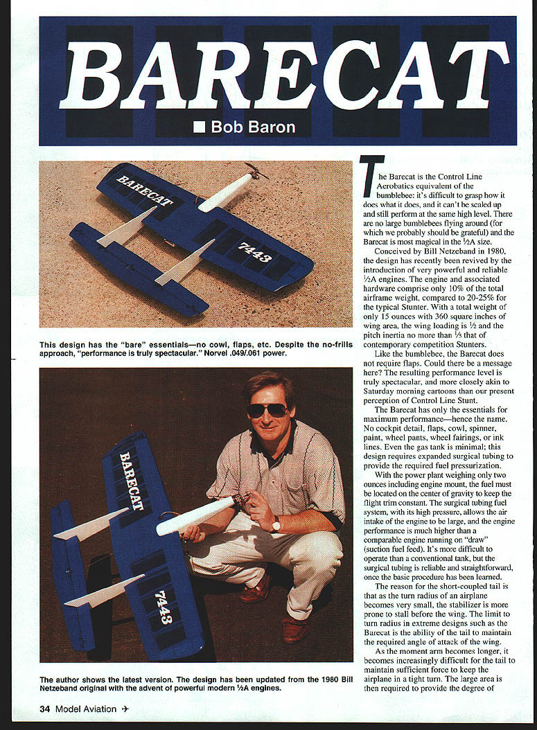
The Barecat is the Control Line Aerobatics equivalent of the bumblebee: it's difficult to grasp how it does what it does, and it can't be scaled up and still perform at the same high level. The Barecat is most magical in the 1/2A size.
Conceived by Bill Netzeband in 1980, the design has recently been revived by the introduction of very powerful and reliable 1/2A engines. The engine and associated hardware comprise only about 10% of the total airframe weight, compared to 20–25% for the typical Stunter. With a total weight of only 15 ounces and 360 square inches of wing area, the wing loading is about half that of typical Stunters, and the pitch inertia is no more than one-fifth that of contemporary competition Stunters.
Like the bumblebee, the Barecat does not require flaps. The resulting performance level is spectacular — more akin to Saturday-morning cartoons than our present perception of Control Line Stunt.
The Barecat contains only the essentials for maximum performance — hence the name. No cockpit detail, flaps, cowl, spinner, paint, wheel pants, wheel fairings, or ink lines. Even the gas tank is minimal; this design requires expanded surgical tubing to provide the required fuel pressurization.
Because the power plant weighs only about two ounces including engine mount, the fuel must be located at the center of gravity to keep the flight trim constant. The surgical-tubing fuel system, with its high pressure, allows a large air intake to the engine and results in much higher performance than the same engine running on suction (draw) feed. It is more difficult to operate than a conventional tank, but the surgical-tubing system is reliable and straightforward once learned.
The short-coupled tail is deliberate: as the turn radius of an airplane becomes very small, the stabilizer is more prone to stall before the wing. The limit to turn radius in extreme designs such as the Barecat is the tail's ability to maintain the required angle of attack for the wing. As the moment arm becomes longer, the tail must develop increasing force to keep the airplane in a tight turn; this is why larger area is required on conventional Stunters versus Combat models.
Once the geometry of the wing and tail are developed, nose length is determined simply to position the center of gravity. Because the engine is so light, an ounce of ballast was used to keep an already long nose from becoming ridiculous.
The landing gear may seem an extravagance, but since this is a Stunter (not a pure Combat model), a gear is used. The original single-wheel gear matched the bare-essential format but required additional skids and was a nuisance when flying with a stooge: the airplane would rock side-to-side in slight gusts and takeoffs were nerve-wracking. The extra wheel is a small price to pay.
SPECIFICATIONS
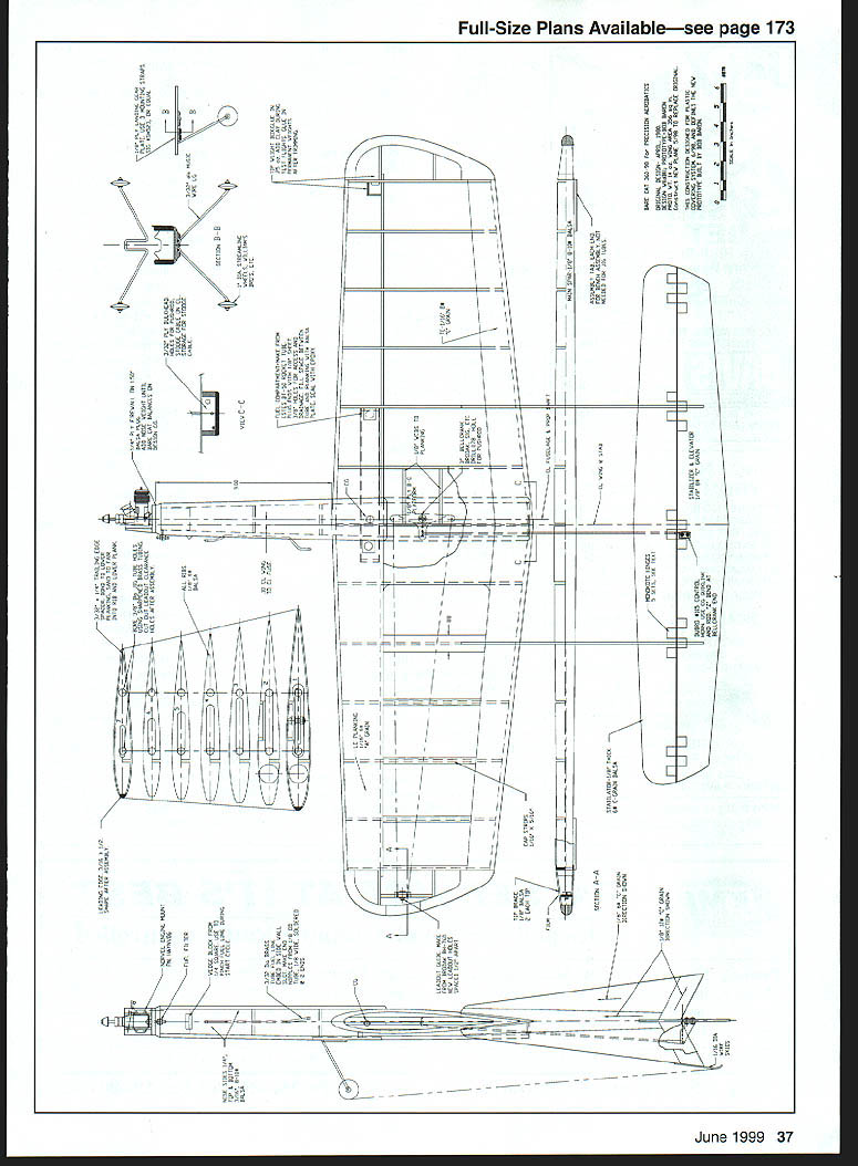
- Type: CL 1/2A Stunt
- Wingspan: 40 inches
- Engine: Norvel .049 / .061 (author prefers .061)
- Flying weight: ~14–15 ounces
- Construction: Built-up
- Covering/finish: MonoKote
- Notes:
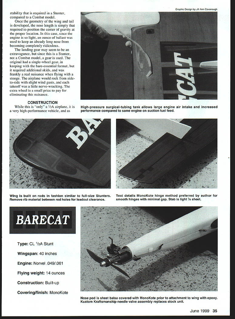
- High-pressure surgical-tubing tank allows a large air intake and increased engine performance compared to suction-fed setups.
- Wing built in rod-spar fashion similar to full-size Stunters.
- MonoKote hinge method preferred by author. Remove rib material between rod holes for leadout clearance. Smooth hinges; minimal gap.
- Stabilizer: light 1/8" sheet.
- Nose pod: 1/16" sheet balsa, covered and MonoKoted prior to attachment to wing with epoxy.
- Kustom Kraftsmanship needle-valve assembly recommended to replace the sensitive stock unit.
CONSTRUCTION
This is "only" a 1/2A airplane, but it is a very high-performance vehicle and requires the same degree of attention to straightness, lightness, and detail as any conventional contest model.
Wing
The wing must be accurate. Build on rods, as pioneered by Al Rabe.
- Make wing ribs by sandwiching the required number of rib blanks between two 1/16" plywood end templates. Pin the templates to the stack of blanks.
- Before carving and sanding the ribs to the templates, cut precision 5/32" holes in the rib blanks using sharpened brass tubing in a drill press.
- Place carved ribs on 3/8" steel rods supported by precision blocks. Work directly over the plans; position ribs exactly and use blocks to keep each rib square to the table when bonding the trailing edge sheeting.
- Glue the 3/32" trailing-edge insert to the trailing edge prior to bonding the bottom trailing edge to the ribs.
- After bonding the bottom trailing edge, place fiberglass tape over the ribs to protect them when sanding the 1/32" insert to match rib contour. Remove tape and bond the top of the trailing edge in place.
- Install the main spar, leading and trailing-edge sheeting, trailing-edge closeouts, and capstrips while the assembly is aligned on the rods.
- Once the rods are removed, cut out the area between the rib holes to provide leadout clearance.
- Complete controls and center-section planking, followed by wingtips, leadout guide, and tip box.
- When sheeting the center section, splice 1/16" sheet on a flat surface to obtain the required width, then cut to fit the center section.
Stab / Elevator
The original Barecat used a geodetic stabilator and a nonlinear bellcrank. To make the design more producible, it was modified to a conventional split stab/elevator with a standard bellcrank.
- Use light 1/8" sheet for the stab/elevator.
- Hinging with minimal weight is critical. The author’s MonoKote hinge method:
- Cut and sand stab and elevator; radius hinge lines.
- Cover both surfaces with MonoKote.
- Prepare two 3"x12" MonoKote sheets: stretch one adhesive-side up on glass, overlay the second adhesive-side down with a 5/8" overlap, and stretch in place.
- Use a metal ruler as a mask and iron the overlap at ~300°F to bond.
- Cut 1/2" strips (use a clear plastic rule as a guide) and trim hinges leaving handling tabs.
- Tack the hinges to one surface (first 1/8"); space hinges in groups of three with 3/32" between hinges.
- Interlay tabs on the mating surface, lay the assembly on glass, stretch and tack the tabs, then iron the entire hinge.
- Mark spanwise, cut excess tabs, and finish by ironing each hinge. Use ~200°F for final bonding to the wood.
- The method is neat, durable, and quick—about 1/2 hour for the operation.
Fuselage / Nose Pod
- The nose pod is made from sheet balsa. Cut the slot for the fuel tube prior to covering.
- Use epoxy for firewall mounting; cyanoacrylate (CYA) is not tough enough for this joint.
- Install details (fuel tube, filter bracket) before attaching the assembly to the wing. MonoKote all components separately and glue in place; cut covering away where wood-to-wood bonds are required.
- Use 30-minute epoxy for all major assembly joints. For fuselage-to-wing, boom-to-wing, and stabilizer-to-boom bonds, tack-glue parts in place and wipe excess epoxy with alcohol. The next day, add a glue fillet and again wipe away excess with alcohol.
Landing Gear
- The Barecat originally used a single-wheel gear to stay minimal but added a second wheel to avoid rocking and troublesome takeoffs when flying with a stooge. The extra wheel stabilizes ground handling and is recommended.
Engine / Fuel System
This is the most novel part of the airplane for many Stunt fliers: a high-pressure surgical-tubing tank used with a small Norvel 1/2A engine.
- Engine:
- Preferred engines: Norvel .049 or .061 (author prefers the .061 for more torque/power at the same weight). New one-piece-case 1/2A engines are also candidates.
- After thorough break-in (may require up to an hour), hand-starts are possible even on pressure. A small electric starter made for 1/2A engines is convenient—ensure the engine is not hydraulically locked before using it.
- The author reduced the .061 intake diameter with 3/32" OD brass tubing epoxied in place with JB Weld to make needling easier on pressure feed; still ample power on 50 feet of .008 cable.
- Kustom Kraftsmanship needle-valve assembly recommended: stock needle is very sensitive on pressure systems; Kustom assembly gives a running range of about 1/4 turn.
- Norvel injection-molded engine mounts are accurate but soft; avoid stripping. Use sheet-metal or self-tapping screws.
- Norvel Freedom plug with 3–4 head gaskets gives good performance but may last only 3–4 flights. A Nelson-plug adapter head (available from Larry Driskill) is more robust.
- Prop options: Tornado 5.5x3, APC 5.7x3 cut to 5.25, or APC 6x2 cut to 5.25, depending on flying style.
- Fuel: 25% nitro with at least half the lubricant as castor oil. Sig 1/2A fuel and Norvel fuel work well.
- Surgical-tubing tank construction and operation:
- Use surgical tubing from a reputable supplier (author uses Sig Manufacturing).
- Slip some 1/16" ID tubing over a small Sig eyelet. Then slip 3/32" ID tubing (1/16" wall thickness) over the eyelet flange and wrap with 24-gauge wire.
- Use 1/16" wall thickness tubing; 1/32" wall thickness is too thin and does not provide uniform pressure.
- Knot the end of the 3/32" tube to seal the tank. Stretch the 3/32" tubing near the eyelet to create a weak spot so the tank fills first at the front when pressurized.
- When filling the tank, always wear safety glasses—an exploding tank can spray fuel.
- Use a large syringe to pressurize/fill the tank. After filling, close off the fuel line with an alligator clip and position the fuel line on the transfer tube in the fuselage. Connect the ignition battery.
- Start procedure:
- Place your finger to cut off fuel flow, pressurize the tank, start the engine, then release your finger.
- Prime by pressing the fuel line against the pinch block, remove the alligator clip, and slowly release pressure to prime the engine. Flip the engine until it fires.
- Modulate pressure on the pinch block to keep the engine running until it comes up to temperature and will run without pressure on the pinch block.
- Needle the engine to just slightly less than full power.
- Use a Du-Bro Ni-Cd starting battery that positively clips to the head for Norvel head/plug. Use alligator clips for a Nelson plug. A secure battery hookup is essential—your hands will be busy with the fuel system on startup.
- Once accustomed to the procedure, starts are relatively easy and the power is impressive—this engine can turn a 5.25x3 at ~27,000 rpm.
- Lines: use seven-strand .008 cable, 50 feet long. Lap times are approximately four seconds. In smooth air, the model can be flown on lines as long as 55 feet.
- Caution: use seven-strand .008 cable; do not use three-strand .008 (marginal for safety and difficult to handle). Brodak sells seven-strand .008 cable (724-966-2726). You can use .012 cable for easier handling, but expect a noticeable loss in performance.
PERFORMANCE AND NOTES
- The Barecat is a challenge to build and fly, but the result is highly rewarding and excellent for sharpening flying skills. The author flew this design exclusively for six months and found it an aid in improving technique; after returning to conventional .40-powered Stunters he won the US Team Trials for the first time.
- After flying the Barecat for a few months, regular Stunters may seem tame by comparison. The added fun and adrenaline more than compensate.
Bob Baron 4957 Dana Dr. Kennesaw, GA 30144
Transcribed from original scans by AI. Minor OCR errors may remain.

