
BareCat 650-C
Bill Netzeband
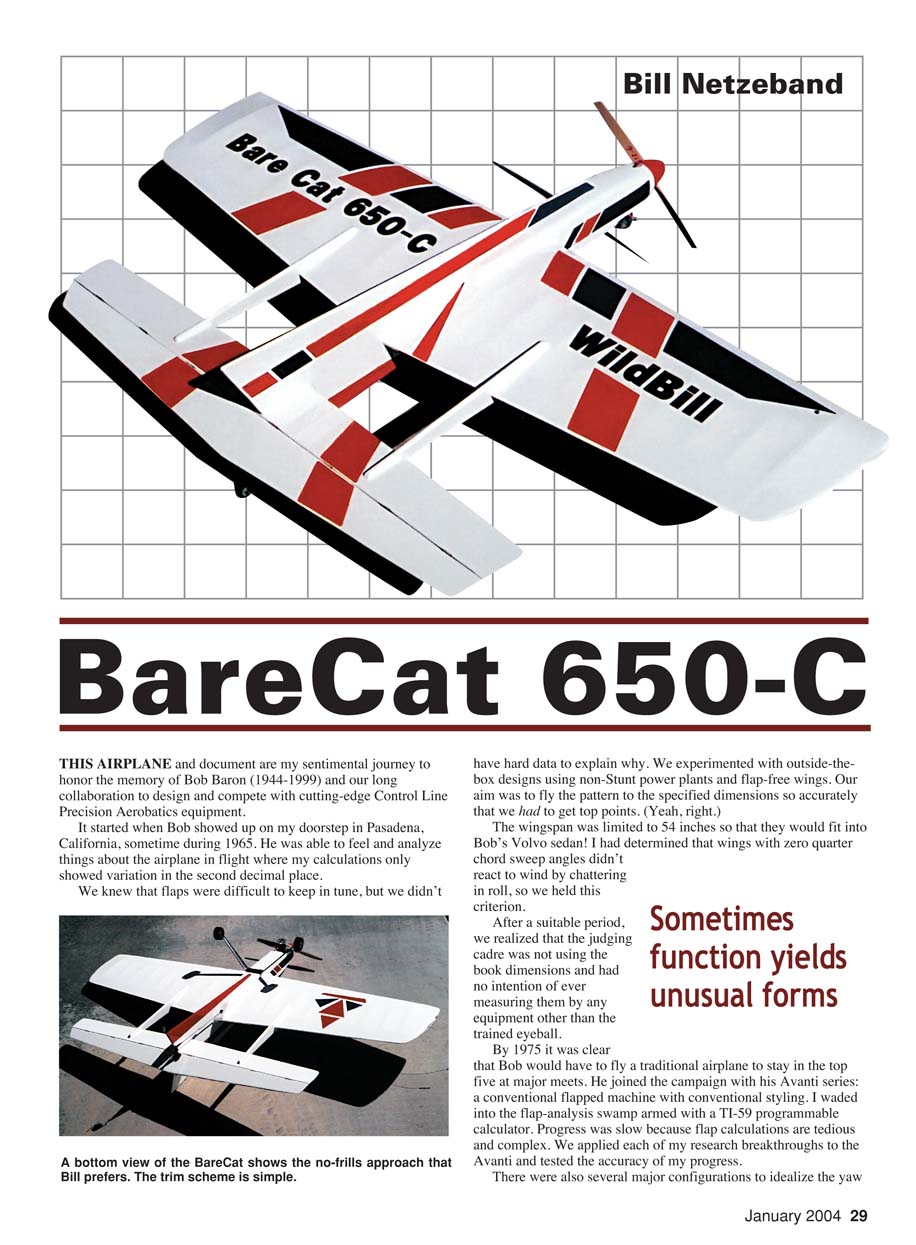
This airplane and document are my sentimental journey to honor the memory of Bob Baron (1944–1999) and our long collaboration to design and compete with cutting-edge Control Line Precision Aerobatics equipment.
It started when Bob showed up on my doorstep in Pasadena, California, sometime during 1965. He was able to feel and analyze things about the airplane in flight where my calculations only showed variation in the second decimal place.
We knew that flaps were difficult to keep in tune, but we didn't have hard data to explain why. We experimented with outside-the-box designs using non‑Stunt power plants and flap‑free wings. Our aim was to fly the pattern to the specified dimensions so accurately that we had to get top points.
The wingspan was limited to 54 inches so that they would fit into Bob's Volvo sedan. I had determined that wings with zero quarter‑chord sweep angles didn't react to wind by chattering in roll, so we held this criterion.
After a suitable period, we realized that the judging cadre was not using the book dimensions and had no intention of ever measuring them by any equipment other than the trained eyeball. By 1975 it was clear that Bob would have to fly a traditional airplane to stay in the top five at major meets. He joined the campaign with his Avanti series: a conventional flapped machine with conventional styling. I waded into the flap‑analysis swamp armed with a TI‑59 programmable calculator. Progress was slow because flap calculations are tedious and complex. We applied each of my research breakthroughs to the Avanti and tested the accuracy of my progress.
There were several major configurations to idealize the yaw axis, the power‑plant package, the landing gear, the Rabe rudder, and to search for the magic flap‑elevator relationship. Along with the aerodynamic package criterion, we added simple structure with maximum longevity. In 1984 I tiptoed into the computer era and was able to get answers more rapidly. Unfortunately I developed all of my programs using arcane software, so I won't be able to provide the math for your design efforts.
It became clear that flaps introduce forces that vary widely with any center‑of‑gravity (CG) shift or a minor velocity change. While flaps can make a possible 40% more lift available to the wing, they load the elevator excessively and demand lots of extra thrust. I kept looking for ways to compete without flaps because I prefer simple solutions, and my skill level peaked out a little bit above average.
Bob and I left off anything that did not contribute to flying the AMA rule‑book pattern dimensions, such as labor‑intensive decorations, artistic shapes, and high finishes, which add up to weight and cost.
The Humbug series, initiated in 1968, was based on 7:1 aspect‑ratio wings controlled by 10:1 aspect‑ratio stabilators, with minimal fuselage and appendages. The stabilators were later replaced by stabilizer‑elevator surfaces. They were also based on low power‑to‑weight ratio airframes. The original Humbug used a Fox .19 to power 490 square inches of wing at 39 ounces. Subsequent versions backed down to 6:1 aspect‑ratio wings and 8:1 stabilizers. They produced positive comments from the general population but missed the winner's circle too often.
The 1/2A BareCat was designed in 1980 to achieve the lowest practical wing loading and to take advantage of reducing the wing aspect ratio to 4:1 and the tail to 6:1. The tail became 30% of the wing, and the tail moment arm was 14 inches. We stored fuel on the CG in a bladder tank since a tank in the 11‑inch nose would upset the CG during flight. The whole 1/2A project went too far outside the box to become a popular configuration.
In 1993 I wrote a story called "The Stunt Ace" and designed a theoretically optimized machine that would do a book pattern. It required a super .09 engine to save dead weight and fuel and to allow .012‑inch‑diameter lines. Fuel was stored in a high‑pressure bladder mounted on the CG, as in the 1/2A BareCat. I had to specify several unobtainium space‑age materials to keep the weight down. It flew great on paper, but Ace missed qualifying at its first Nats by a half point.
The machine had a 600‑square‑inch wing, huge centerline fin surfaces, a single wheel, booms, a stabilator, etc., and only weighed 15 ounces. Bob enjoyed the story and asked me if it would fly with a .15 engine. He built the BareCat 600 from my sketches using a Nelson .15 Combat engine. The puzzlement came when the 40‑ounce machine flew off the bench, and the few times Bob and the Nelson got together with the needle valve and the experimental bladder fuel system, it handled like an eagle! Those happy moments were too few, and Bob shelved it.
I got my hands on the airframe in 1998 and tried a Norvel .15. I replaced the stabilator and nonlinear bellcrank with a 50% stabilizer‑elevator assembly. The thing teased me by flying all of the maneuvers, but it couldn't deliver adequate confidence. It ended up with a Double Star .40, a conventional fuel tank in the nose, it gained 7 ounces, and it became a better‑than‑average performer. There was not enough sizzle, though.
Bob had a final adventure using the BareCat '98 that was published in the June 1999 Model Aviation. He took it to the 1998 Nationals for recreation. Tragically, his Spartan broke up during a test flight after he had qualified for the finals. Being a consummate competitor, Bob decided to fly the BareCat.
Several problems, in addition to being first up to fly the next day, prompted an all‑nighter. He'd been flying with .008‑inch lines on the airplane powered by a 1cc engine. The last trimming trauma was a frantic session to install a combat‑tuned VA .049. He had help from Larry Driskill and "Sleepy" Dawson. After little real sleep, they got in a fast test flight at 6 a.m. Bob's first flight was humming along when the engine mount broke and the VA sailed off into the boondocks. Bob finessed it back to the runway with no further damage.
The next frantic fix involved reinstalling the 1cc engine and a set of "equivalent" .012‑diameter lines. With no test flight, Bob racked up a 500‑point score from the Nationals judges—not too shabby for an outside‑the‑box machine.
In 1998 Tom Dixon was producing a Double Star 50, and we decided to give the BareCat another shot. We used the 1/2A BareCat geometry and enlarged it to produce 650 square inches of wing. After reviewing the layout, we adjusted the tail moment arm and stabilizer aspect ratio to more reasonable sizes for a large airplane.
Bob constructed the first model and used an inverted Double Star 50 engine and spinner. That airplane was almost finished when he passed away in September 1999. Tom Dixon finished Bob's model and flew it a few times. It needed flight trimming, but Tom and I decided that Bob's last project shouldn't be put at any more risk.
To make Bob's airplane unique, I modified the drawings to use an upright engine and aluminum two‑wheel landing gear. I built the "A" model and powered it with a Double Star 50. While tolerating nose‑heavy trim, I crashed it inverted, broke the engine, and cracked a few major joints. During the repair phase I shortened the nose to move the CG to the design location, and Tom replaced the engine. The next flight series was truncated at four. The partially tuned BareCat was feeling good, and I tried an Hourglass. I ham‑handedly executed the first corner and the model came loose on the second corner, quickly hiding behind my hat, and augered into the unyielding ground before I could turn around.
There were several large pieces, but none of them had joints that lent themselves to reconstruction. Besides that, the new engine was split open after the fuel tank mashed around it, and the engine beam mounts made a wishbone out of the engine crankcase.
Post‑mortem analysis revealed that the twin‑finned design had excessive yaw stability but inadequate side area to generate enough yaw torque to recover from extreme adverse yaw. Bob never overcontrolled a model, so the problem didn't show up until I got my hands on one. The twin‑finned BareCat 650 project ended with two prototypes, and I moved on to the B model.
The BareCat 650‑B incorporated the single‑finned side view of the old 600, a sidewinder engine on a Radio Control engine mount, and it preserved the now‑proven 650 plan‑view geometry. I used a 4‑year‑old Silver Fox .40 to take advantage of the .015‑diameter cable. This is a powerful engine. I settled on 10% fuel and an APC 12.25 x 3.75 propeller.
This allows a rich, level flight and plenty of reserve thrust for the vertical maneuvers. It comes on and off reliably, and with a 20% oil blend it needs less than 4 ounces to complete the pattern.
Trimming the model was straightforward and surprise‑free. I cleaned up the slight tendency to turn tighter outside by sliding the lines down on the handle to adjust my leverage and feel. The 650‑B at 54 ounces competes in the Advanced class with good results for me. I currently fly it with a Tom Dixon‑prepared O.S. .46 LA and use 66 feet of that dreaded .018‑diameter cable required by rules. We sincerely believe that too much horsepower is about right.
I wouldn't expect those competing in the Expert class to use something as simple as this machine as their competition mount. This is an excellent airplane with which to work your way up through the ranks before you have to start the arduous task of keeping a flap model in tune.
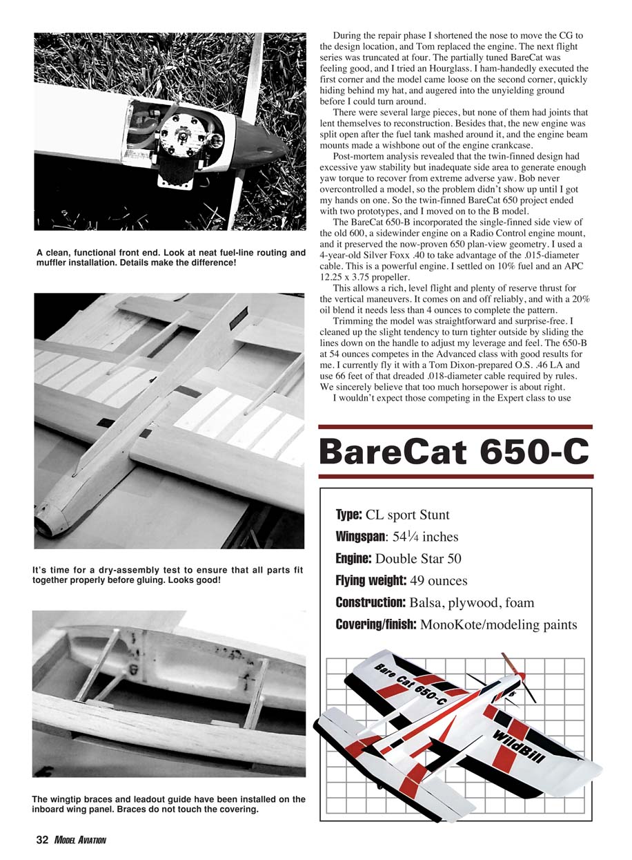
BareCat 650‑C — Overview
Type: CL sport Stunt Wingspan: 54¼ inches Engine: Double Star 50 Flying weight: 49 ounces (dry for prototype C) Construction: Balsa, plywood, foam Covering/finish: MonoKote / modeling paints
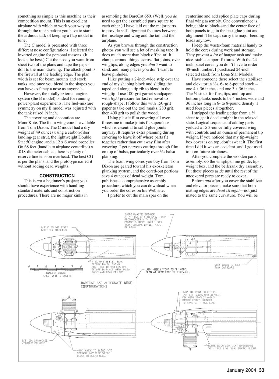
The C model is presented with three different nose configurations. I selected the inverted engine for personal reasons (it looks the best). Cut the nose you want from sheet two of the plans and tape the paper doll to the main drawing. The attach point is the firewall at the leading edge. The plan width is set for beam mounts and stock tanks, and once you blend in the shapes you can have as fancy a nose as anyone's.
However, the totally external engine system (the B model) is ideal for running power‑plant experiments. The fuel‑mixture symmetry on my B model was adjusted with the tank radius set at 1/8 inch.
The covering and decoration are MonoKote. The foam wing core is available from Tom Dixon. The C model had a dry weight of 49 ounces using a carbon‑fiber landing‑gear strut, the lightweight Double Star 50 engine, and a 12 x 6 wood propeller. On 68 feet (handle to airplane centerline) x .018‑diameter cables, there is plenty of reserve line tension overhead. The best CG is per the plans, and the prototype nailed it without adding dead weights.
CONSTRUCTION
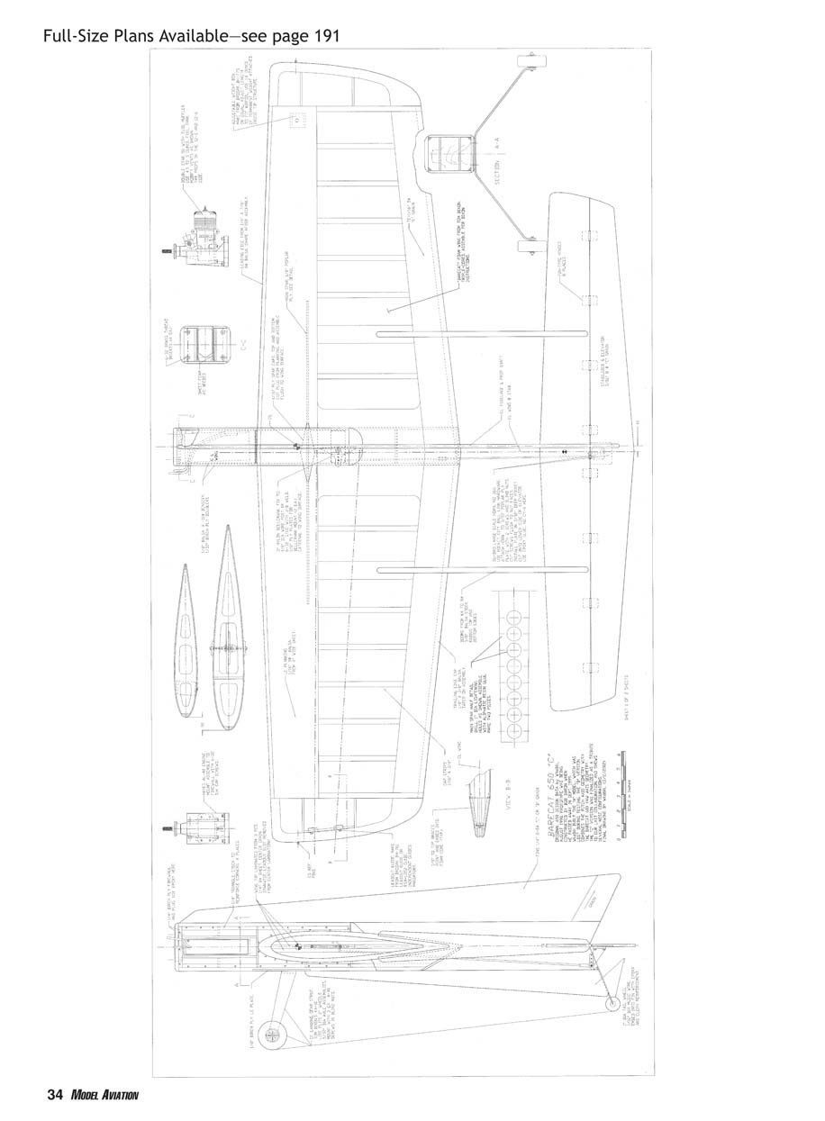
This is not a beginner's project; you should have experience handling standard materials and construction procedures. There are no major kinks in assembling the BareCat 650, but you do need to get the assembled parts square to each other. I have laid out the major parts to provide self‑alignment features between the fuselage and wing and the tail and the airplane.
As you browse through the construction photos you will see a lot of masking tape. It does much more than block off paint: it clamps around things, across flat joints, over wingtips, along edges you don't want to sand, and many other places you don't want to leave pinholes.
I like putting a 2‑inch‑wide strip over the end of my shaping block and sliding the taped end along a tip rib to blend in the wingtip. I use 100‑grit garnet sandpaper with light pressure for fast removal to rough‑shape, then 150‑grit to take out tool marks, followed by 280 and 400 grit to polish the wood.
Using plastic film covering all over forces me to make joints fit super‑close, which is essential to solid glue joints anyway. It requires extra planning during construction to leave it off where parts fit together rather than cutting away film after covering. I get nervous cutting through film on top of balsa, particularly over 1/16" balsa planking.
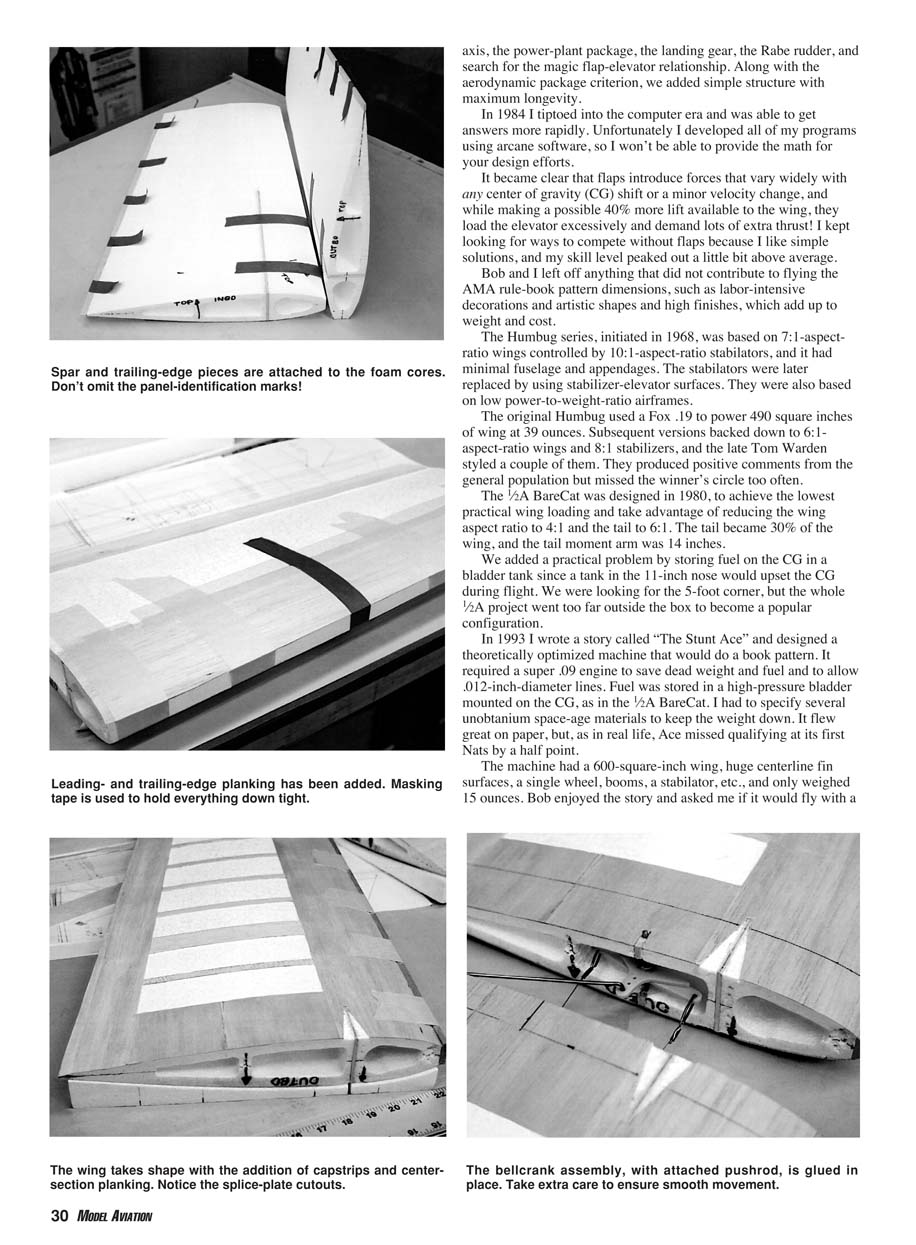
The foam wing cores you buy from Tom Dixon are geared toward his exoskeleton planking system, and the cored‑out portions save 4 ounces of dead weight. Tom publishes a comprehensive assembly procedure, which you can download when you order the cores from his web site.
I prefer to cut the main spar on the centerline and add splice plate caps during final wing assembly. One convenience is being able to block‑sand the center face of both panels to gain the best glue joint and alignment. The caps carry the major bending loads.
I keep the waste‑foam material handy to hold the cores during work and storage. They prevent a lot of hangar rash and make nice, stable support fixtures. With the 24‑inch panel cores, you don't have to order 48‑inch lumber. I purchased 24‑inch selected stock from Lone Star Models.
Have someone select the stabilizer and elevator in 1/16", 6‑ to 8‑lb balsa stock — one 4 x 36 inches and one 3 x 36 inches. The 1/4" stock for fins, tips, and top and bottom planks needs to be 4 inches wide and 36 inches long in 6‑ to 8‑lb density. I used four pieces altogether.
I stripped the leading edge from a 1/4" sheet to get it dead straight in the relaxed state. Logical sequencing of adding parts yielded a 15.3‑ounce fully covered wing with controls and an ounce of permanent tip weight. If you noticed that my tip‑weight box cover is on top, don't sweat it—the first time I did it was an accident, and I got used to it on future airplanes.
After you complete the wooden parts assembly, do the wingtips, line guide, tip‑weight box, and the bellcrank dry assembly. Put these pieces aside until the rest of the uncovered parts are ready to cover.
Before and after you cover the stabilizer and elevator pieces, make sure that both mating edges are dead straight—not just mated to the same curvature. You will be rewarded with an elevator that drops freely by its own weight. Careful location and cutting of hinge slots will save you problems during final assembly, when the parts are all covered and polished.
The control‑horn base takes a bit of skill but gives a clean, fuelproof assembly. Make sure that the horn is located on the bottom and the inboard side before you cut the pocket. I cut out the fin parts at the same time as the stabilizer parts and get into a rhythm of rounding edges, block‑sanding, and polish‑sanding these parts.
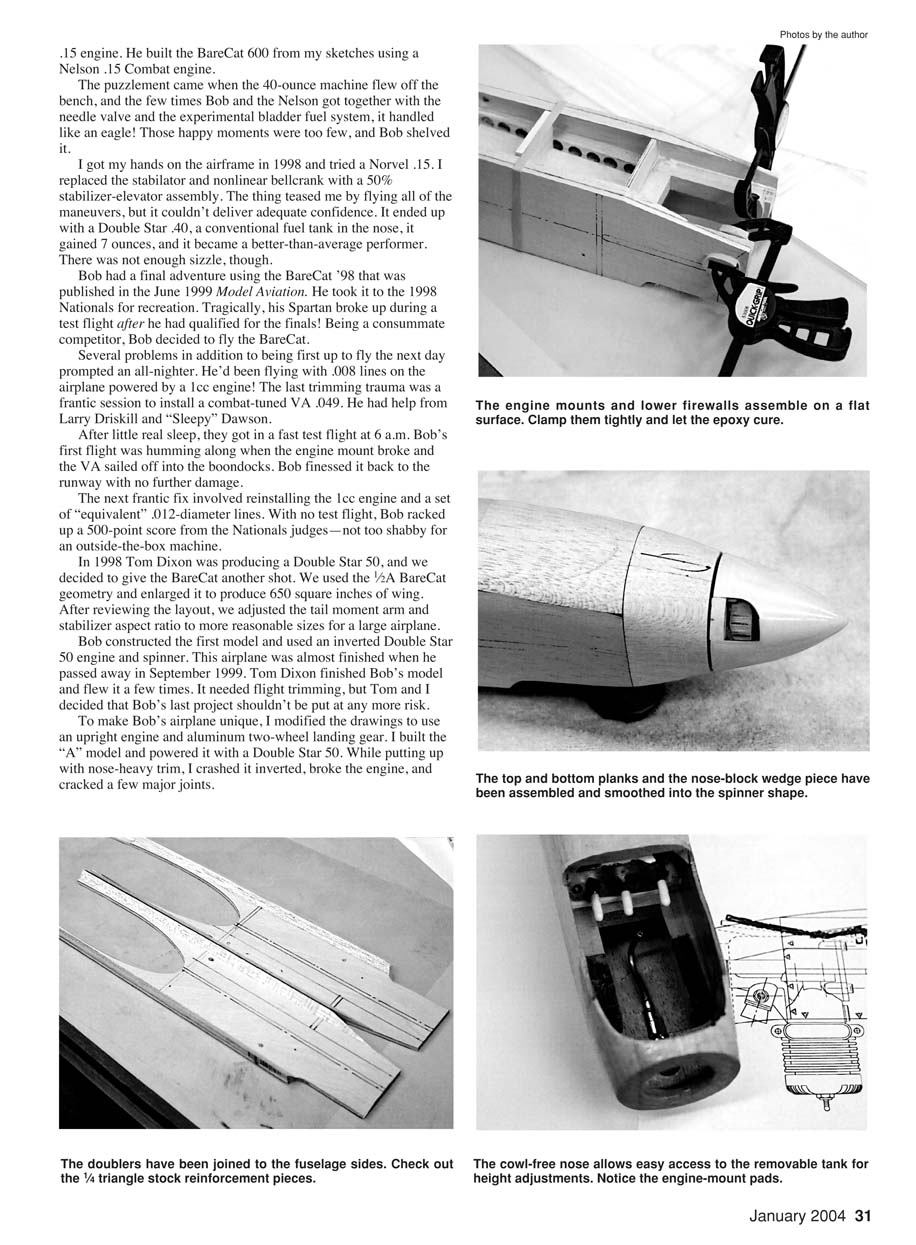
I drilled a series of 1/2‑inch holes along the engine mounts to save dead weight. Using a Forstner drill bit I let the center point just break out of the hole's bottom, which leaves a solid glue surface. I use 1/8‑inch dowel pins to key the fuselage sides and doublers during their glue process. I use epoxy, well squeegeed, and apply a great deal of pressure between flat surfaces to gain optimum joint strength. The pins are sanded on both sides until flush to both surfaces.
I make a subassembly of the engine mounts, two subfirewalls and the spacer block, and the filler piece, assembled squarely and flat using epoxy. This group is used to square and align the fuselage sides and top assembly on a nice, flat surface. If this assembly is true, the final product works better.
Thoroughly coat with epoxy the inside surfaces that will be exposed to fuel. Do the engine mounting holes and spacer plates, then tape up the engine. Mount it and a sacrificial spinner and carve the nose. Here you should have the uncovered wood parts ready for final assembly.
Final Assembly
- Tape the wing halves together and dry‑assemble the fuselage to the wing.
- Use a flat tabletop to fit the top fin and the booms and stabilizer together.
- Once these joints are tuned to firm slip fits, proceed with covering the parts. The closer these joints fit, the better the strength, and you can really get quality without fillets to cover the gaps.
- Glue final joints carefully, ensuring parts are square.
- Add all of the deadweight parts: landing gear assembly, control horn, pushrod half, fuel tank and padding, and plumbing.
The covering and decorations are up to you and your comfort level. One thing Bob and I learned is that the appearance points awarded now far outweigh the 80 points awarded in the early days of Stunt; appearance judging has changed design direction away from the ugly barn‑door machines.
Flying
If your finished CG is within 1/8" of the design location, you might as well proceed to flight tests. The lines' location on the plans are for the design CG and a 50‑ounce dry weight. You can tune your model from there as you get used to it.
I was able to hit the design CG right on with a wood propeller, and so far the lines rake is correct using 66‑foot x .018‑diameter cables, eyelet to eyelet. This delivers a flight radius, including 2.5 feet for my extended arm, of 70.8 feet.
I have an ounce of tip weight in the box, for a total of 2 ounces. I am still playing the propeller and tank‑height game while feeling safe to ease through all of the pattern maneuvers. I learned that 6.0‑second laps are too slow and that 5.5 seconds brings up safe tension and control forces.
The Double Star 50 is performing routinely with no bad habits on 10% nitro fuel. I still need to stabilize the power‑plant components before determining the ideal fuel capacity. It will probably be less than 5 ounces.
Since Bob is no longer available to make my numbers sing, will there be more BareCat type projects? The three models presented here represent optimal geometry under the present pattern specifications. Someone could probably shave off a few ounces with carbon fiber and a lost‑foam wing structure, but the resulting machinery would not present enough improvement to warrant the additional effort.
I believe that any of the top‑10 pilots could compete successfully with a BareCat 650. Brave words, for sure, but I don't believe any of them will try it. Don't feel sorry for me; I had my time in the barrel and am ready to coast a bit. Please try the BareCat—you'll like it!
Thanks, Bob. It was a fun run.
MA Bill Netzeband 23978 Villa Pammila Murrieta, CA 92562
Materials Sources
- Foam wing cores (BareCat), Bolly landing gear (KA‑10), Double Star 50 engine:
Tom Dixon Box 671166 Marietta, GA 30062 Tel/Fax: (770) 592‑3279 http://members.tripod.com/~TomDixon/tomdixon.htm
- Fuel tank, controls, wheels, propellers:
Brodak Mfg. & Distributing Co. Inc. 100 Park Ave. Carmichaels, PA 15320 (724) 966‑2726 Fax: (724) 966‑5760 www.brodak.com
- Fuel tank, controls, wheels, propellers:
RSM Distribution 21899 Heliotrope Ln. Wildomar, CA 92595 (714) 931‑6038 www.rsmdistribution.com
- Selected‑density balsa (see plans):
Lone Star Models 115 Industrial Lancaster, TX 75134 (972) 218‑9663 (800) 687‑5555 (to order) Fax: (972) 218‑9211 www.lonestar‑models.com
Transcribed from original scans by AI. Minor OCR errors may remain.

