
Barnabus
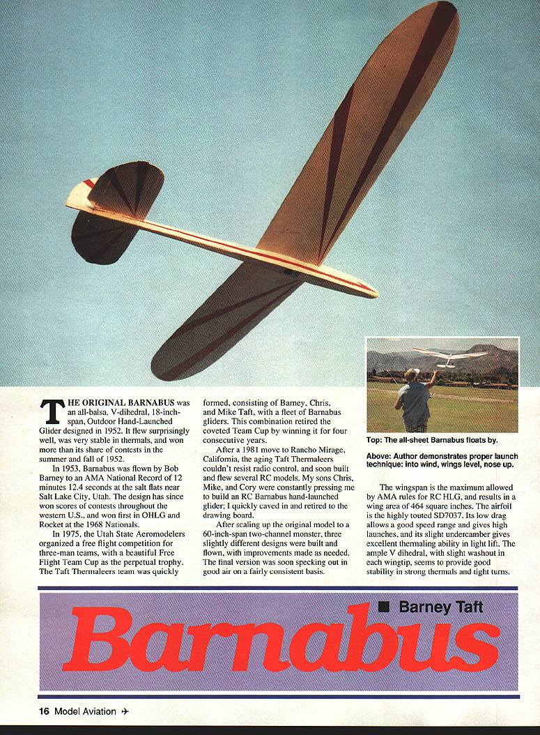
The original Barnabus was an all‑balsa, V‑dihedral, 18‑inch‑span Outdoor Hand‑Launched Glider designed in 1952. It flew surprisingly well, was very stable in thermals, and won more than its share of contests in the summer and fall of 1952.
In 1953, Barnabus was flown by Bob Barney to an AMA national record of 12 minutes 12.4 seconds at the salt flats near Salt Lake City, Utah. The design has since won scores of contests throughout the western U.S., and won first in OHLG and Rocket at the 1968 Nationals.
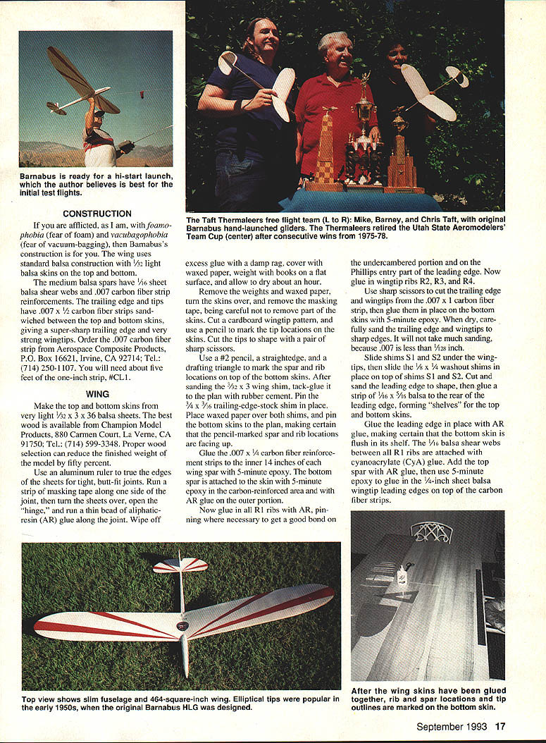
In 1975, the Utah State Aeromodelers organized a free‑flight competition for three‑man teams, with a beautiful Free Flight Team Cup as the perpetual trophy. The Taft Thermaleers team was quickly formed, consisting of Barney, Chris, and Mike Taft, with a fleet of Barnabus gliders. This combination retired the coveted Team Cup by winning it for four consecutive years.
After a 1981 move to Rancho Mirage, California, the aging Taft Thermaleers couldn't resist radio control, and soon built and flew several RC models. My sons Chris, Mike, and Cory were constantly pressing me to build an RC Barnabus hand‑launched glider; I quickly caved in and retired to the drawing board.
After scaling up the original model to a 60‑inch‑span two‑channel monster, three slightly different designs were built and flown, with improvements made as needed. The final version was soon specking out in good air on a fairly consistent basis.
The wingspan is the maximum allowed by AMA rules for RC HLG and results in a wing area of 464 square inches. The airfoil is the highly touted SD7037. Its low drag allows a good speed range and gives high launches, and its slight undercamber gives excellent thermaling ability in light lift. The ample V dihedral, with slight washout in each wingtip, seems to provide good stability in strong thermals and tight turns.
CONSTRUCTION
If you are afflicted, as I am, with foamo‑phobia (fear of foam) and vacubagophobia (fear of vacuum‑bagging), then Barnabus's construction is for you. The wing uses standard balsa construction with 1/32 light balsa skins on the top and bottom.
The medium balsa spars have 1/16 sheet balsa shear webs and .007 carbon‑fiber strip reinforcements. The trailing edge and tips have .007 x 1/2 carbon fiber strips sandwiched between the top and bottom skins, giving a super‑sharp trailing edge and very strong wingtips. Order .007 carbon fiber strip from Aerospace Composite Products, P.O. Box 16621, Irvine, CA 92714; Tel: (714) 250‑1107. You will need about five feet of the one‑inch strip, #CL1.
WING
Make the top and bottom skins from very light 1/32 x 3 x 36 balsa sheets. The best wood is available from Champion Model Products, 880 Carmen Court, La Verne, CA 91750; Tel: (714) 599‑3348. Proper wood selection can reduce the finished weight of the model by fifty percent.
Use an aluminum ruler to true the edges of the sheets for tight, butt‑fit joints. Run a strip of masking tape along one side of the joint, then turn the sheets over, open the "hinge," and run a thin bead of aliphatic resin (AR) glue along the joint. Wipe off excess glue with a damp rag, cover with waxed paper, weight with books on a flat surface, and allow to dry about an hour.
Remove the weights and waxed paper, turn the skins over, and remove the masking tape, being careful not to remove part of the skins. Cut a cardboard wingtip pattern, and use a pencil to mark the tip locations on the skins. Cut the tips to shape with a pair of sharp scissors.
Use a #2 pencil, a straightedge, and a drafting triangle to mark the spar and rib locations on top of the bottom skins. After sanding the 3/32 x 3 wing shim, tack‑glue it to the plan with rubber cement. Pin the 3/4 x 1/8 trailing‑edge‑stock shim in place. Place waxed paper over both shims, and pin the bottom skins to the plan, making certain that the pencil‑marked spar and rib locations are facing up.
Glue the .007 x 1/4 carbon‑fiber reinforcement strips to the inner 14 inches of each wing spar with 5‑minute epoxy. The bottom spar is attached to the skin with 5‑minute epoxy in the carbon‑reinforced area and with AR glue on the outer portion.
Now glue in all R1 ribs with AR, pinning where necessary to get a good bond on the undercambered portion and on the Phillips entry part of the leading edge. Now glue in wingtip ribs R2, R3, and R4.
Use sharp scissors to cut the trailing edge and wingtips from the .007 x 1 carbon fiber strip, then glue them in place on the bottom skins with 5‑minute epoxy. When dry, carefully sand the trailing edge and wingtips to a sharp edge. It will not take much sanding, because .007 is less than 1/32 inch.
Slide shims S1 and S2 under the wingtips, then slide the 1/8 x 1/4 washout shims in place on top of shims S1 and S2. Cut and sand the 1/16 x 5/16 balsa to shape, then glue a strip of 1/16 x 5/16 balsa to the rear of the leading edge, forming "shelves" for the top and bottom skins.
Glue the leading edge in place with AR glue, making certain that the bottom skin is flush in its shelf. The 1/16 balsa shear webs between all R1 ribs are attached with cyanoacrylate (CyA) glue. Add the top spar with AR glue, then glue the inner 14‑inch carbon‑reinforced area to the bottom spar with 5‑minute epoxy.
Glue the dihedral gussets to one half of the wing with AR, using clothespins to hold them in place. Allow to dry thoroughly.
Attach the top skins as follows: apply 30‑minute epoxy to the .007 carbon‑fiber trailing edge, wingtips, and top spar reinforcements. Now apply AR glue liberally to all ribs, the balsa portion of the top spar, and the balsa portion of the wingtip leading edge. Position the top skin, pin down the leading edge, carefully fit the skin to the shelf, then weight the skin with several thick magazines to get a good bond to each rib. Use several clothespins to hold the wingtips tightly together until thoroughly dry.
Glue the wing halves together with AR, blocking up each tip five inches. When dry, lightly sand the wing with 400‑grit paper; be very careful not to sand through the skins. Glue plywood reinforcement F7 to the top of the wing, then drill for an 8‑32 nylon bolt. Drill the leading edge of the wing for a 1/8 birch dowel, and glue in place with CyA.
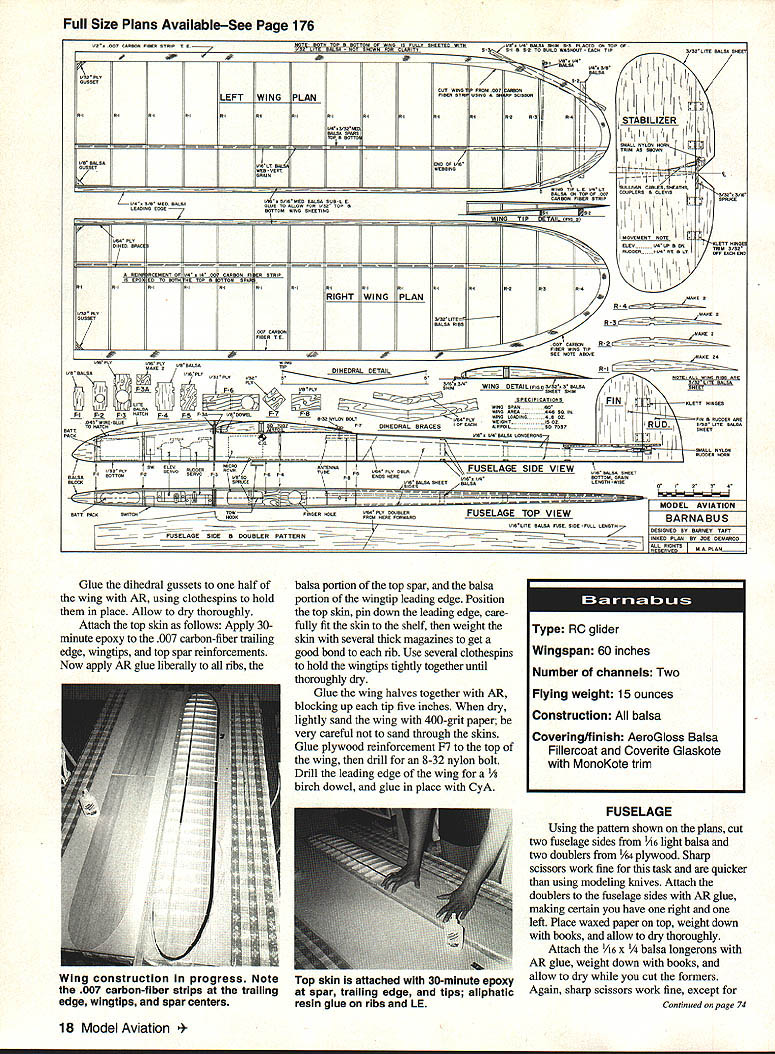
Specifications
- Type: RC glider
- Wingspan: 60 inches
- Number of channels: Two
- Flying weight: 15 ounces
- Construction: All balsa
- Covering/finish: AeroGloss Balsa Fillercoat and Coverite Glaskote with MonoKote trim
FUSELAGE
Using the pattern shown on the plans, cut two fuselage sides from 1/16 light balsa and two doublers from 1/64 plywood. Sharp scissors work fine for this task and are quicker than using modeling knives. Attach the doublers to the fuselage sides with AR glue, making certain you have one right and one left. Place waxed paper on top, weight down with books, and allow to dry thoroughly.
Attach the 1/16 x 1/4 balsa longerons with AR glue, weight down with books, and allow to dry while you cut the formers. Again, sharp scissors work fine for most cutting; use a modeling knife where necessary. Cut the formers from balsa with the grain running lengthwise, and glue in place with CyA.
Use CyA to attach F6 to the top of the bottom plywood cover, as well as the .045 wire tow hook. The 1/16 plywood finger hole is also glued to the bottom of the 1/32 plywood bottom with CyA. Cut the balsa nose block to shape, and glue in place.
Drill and tap the 1/8 plywood former F8 to receive the 8‑32 nylon wing bolt. This gives a strong, snug wing hold‑down without the use of a flaky blind mounting nut.
RADIO INSTALLATION
Install microservos with servo‑mounting tape, attaching them securely to both the bottom and the sides of the fuselage as shown on the plans. After placing the battery pack and micro receiver in position, install the #507 Sullivan control‑rod sheaths, making certain you glue them to the fuselage sides in several places to prevent buckling.
Make Z‑bends in the control rods where they hook up to the servos, then strengthen them by running a coat of solder on the rods for about six inches past the bends. This gives a snug, light‑weight, slip‑free connection.
Place the control rods in their sheaths, and hook the control rods to the servos. Attach the rudder control rod to the outermost servo‑arm hole and the elevator control rod to the innermost servo‑arm hole. This gives maximum rudder movement and minimum elevator movement. The control rods and sheaths exit at the fuselage rear, but do not cut them to exact length until after the tail has been installed.
TAIL
Cut the fin, rudder, stab, and elevator from very light 3/32 sheet, sand the edges round, and install #RK2‑7 Klett hinges. I trimmed 3/32 from the ends of each hinge to save weight and make installation easier.
Glue the tail to the fuselage with CyA, and attach the smallest control horns you can locate. (If you can't locate any that are small enough, make your own from 1/16 plywood.) Cut the control‑rod sheaths and control rods to the proper length, then attach the #507 Sullivan clevises, leaving room for final adjustments by screwing in or out. Adjust throw to give 1‑1/4 inches of rudder and 1/4 inch of elevator each way.
Glue in the receiver antenna tube, then glue on the 1/16 balsa top rear fuselage cover with the grain running crosswise. Carve the front fuselage hatch from soft balsa, and glue in the .045 wire front hold‑down. The rear hold‑down is with a small servo screw into former F3. The rear portion of the hatch is glued to the wing.
COVERING/PAINTING
The original was given two coats of AeroGloss Balsa Fillercoat (sanded with 400‑grit paper after each coat) and one coat of Coverite Glaskote. This gives a light, glossy finish to which MonoKote trim can be applied.
Other coverings may be used, but their weight should be considered. Litespan is the lightest and is available from Charlie's R/C Goodies, 2828 Cochran Street, Suite 281, Simi Valley, CA 93065; Tel: (805) 581‑5061. Coverite's Micafilm is the next lightest; then come any of the other popular iron‑ons such as MonoKote, UltraCote, etc. Use these if you aren't too concerned about weight.
FLYING
The most important part of preflight preparation is properly locating the center of gravity. Make certain that your model balances exactly 2‑1/2 inches from the leading edge of the wing. You will probably have to add at least an ounce of lead to the nose to achieve this balance point.
Transcribed from original scans by AI. Minor OCR errors may remain.

