
BDF-1
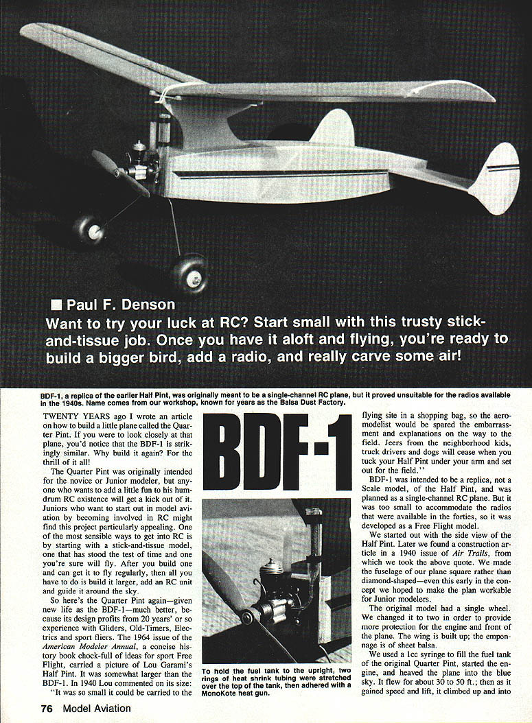
BDF-1, a replica of Lou Garami's earlier Half Pint, was originally meant to be a single-channel RC plane but proved unsuitable for the radios available in the 1940s. The name comes from our workshop, long known as the Balsa Dust Factory.
Twenty years ago I wrote an article on how to build a little plane called the Quarter Pint. The BDF-1 is strikingly similar and has been given new life, improved by two decades of experience with gliders, old-timers, electrics and sport fliers. The Half Pint was described in a 1940 issue of Air Trails as so small it could be carried to the flying site in a shopping bag. The BDF-1 was intended as a replica (not a scale model) of the Half Pint and was originally planned as single-channel RC, but because it was too small for the radios of the era it was developed as a Free Flight model.
The Quarter Pint/BDF-1 is excellent for juniors starting in model aviation and for any modeller who wants a simple, well-proven stick-and-tissue project. Build one, learn to fly it reliably, then scale it up or add radio if you wish.
Flight memory
We used a 1 cc syringe to fill the fuel tank of the original Quarter Pint, started the engine, and launched the plane. It flew 30–50 feet, gained speed and climbed into a loop, rolled out at the top and continued circling right until the fuel ran out. Then the rudders took over, the plane circled left and floated gently to the ground. Those magical flights inspired the BDF-1 revival.
Construction
We suggest you start by kitting the plane. Look over the parts list on the plans, visit your local hobby shop and stock up on everything you don’t already have in the workshop.
Key adhesives and tools mentioned:
- Cyanoacrylate adhesives (thick and thin)
- Kick‑It accelerator (speeds CA set)
- Sandpaper (various grits)
- Hobby razor, small brushes
- Waxed paper or plastic wrap for building
- Small drill and drill bits
- Heavy thread for sewing landing gear
- Small dowels or round toothpicks for wing hold‑down
Fuselage
- Build the right fuselage side first. Pin the 1/16‑in. fuselage side filler to the plans and glue in all longerons and crosspieces. Prop the fuselage filler 1/16 in. above the plans, then finish the construction with 3/32‑in. sq. balsa where called for.
- Build the left fuselage side in the same manner.
- Pin the right side back to the plans and glue formers F3 and F4 in place, ensuring they are perpendicular to the side. Glue the left side in place atop the two formers.
- Sew the landing gear to former F1 as indicated on the plans. Check the location of the blind‑mounting nuts that will secure the engine to the firewall to ensure the landing gear does not interfere. Work the blind nuts into the back side of the firewall and add a drop of UFO (or CA) to hold them in place.
- Remove the fuselage from the plans, insert former F1 and glue in place. Drill the firewall for the four blind‑mounting nuts.
- Level the fuselage by inserting a block under the firewall, then pin the fuselage to the plan to keep it true. Bring the tail end together by squeezing it between two food cans (or similar supports) so the rims touch the longeron lines on the plans. Insert and glue the top and bottom tail crosspieces and all cross braces along the fuselage.
- Fill the bottom area between F1 and F2 with 1/16‑in. sheet balsa.
- Cut three pylon sections from 1/16‑in. sheet balsa. Laminate these pieces with CA (UFO Thick and Thin work well); note grain direction—two outside layers vertical grain and one inside layer horizontal grain.
- Remove the fuselage from the plans and insert the pylon between formers F2 and F4. This is critical: the wing incidence is determined by the pylon location. Mark centerlines on the formers and duplicate plan measurements from the top of each former to the top of the pylon. Glue the pylon in place.
- Add the wing platform atop the pylon and brace it with 1/4‑in. triangular stock. Add 3/32‑sq. strips as dihedral fillers. Drill holes and add the wing hold‑down dowels (round toothpicks).
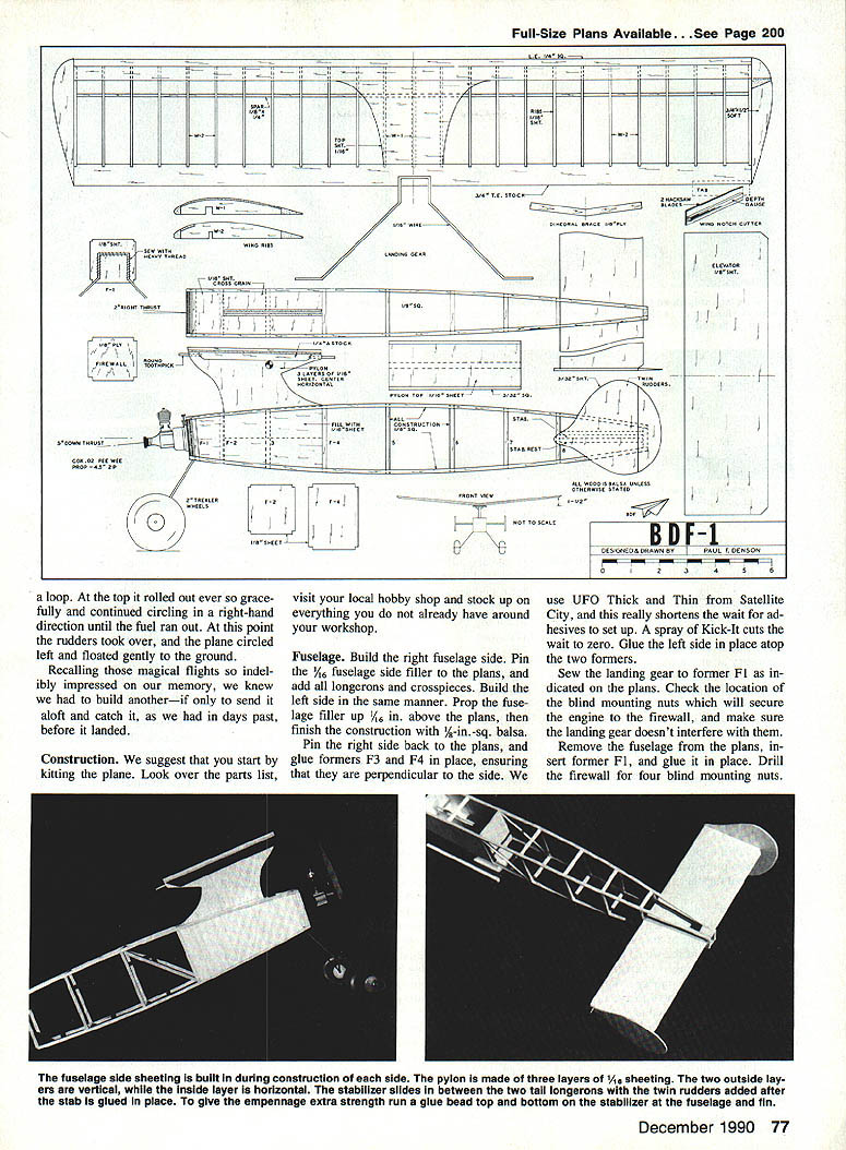
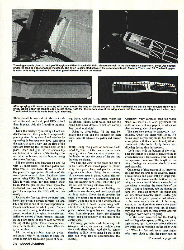
The fuselage side sheeting is applied during construction. The stabilizer slides between the two tail longerons. Twin rudders are added after the stabilizer is glued in place to give the empennage extra strength—run a bead of glue along the top and bottom of the stabilizer where it contacts the fuselage and fin.
Wing
- Use waxed paper or plastic wrap over the plans. Pin the trailing edge stock in place.
- Using ribs as spacers, pin the center spar in place. Add all ribs except the two center W1s and glue. Add and glue the leading edge spar.
- When the glue has set, cut the wing into two halves.
- Remove pins holding one half, prop that tip up about 3 in., check fit between spars and sand a bevel in one wing half using the edge of the workbench as a guide. Fit and glue the two halves together.
- When glued, remove the wing from the plans, insert the dihedral brace and glue it securely to the side of the center spar.
- Make wing tips from soft triangular stock or whittle them from soft sheet balsa.
- Add 1/16‑in. center sheeting. Cut a small notch in the first W2 ribs to accommodate this sheeting.
- For trailing edge notches, use two hacksaw blades taped together and tape a gauge to limit cut depth.
Assembly and Covering
- Carefully sand the entire model using blocks of sandpaper glued to plywood for flat sanding.
- Covering the wing and fuselage:
- Determine the spanwise tear direction of tissue (tear corner to see grain).
- Cut a piece of tissue about 1/2 in. larger on all sides than the area to be covered.
- Lay tissue on the bottom of the wing, run a line of dope thinner where the tissue touches the centerline, and rub the tissue so dope comes up through and dries quickly.
- Stretch the tissue spanwise and attach at the tips and along leading/trailing edges using thinner as needed.
- Trim paper back to spars with a sharp razor and cement edges down with dope applied by a brush. Smooth ragged edges with fine sandpaper.
- Shrink the covering by misting with water, then pin the wing half to the bench with balsa blocks between pins and wing to protect the covering. Allow to dry thoroughly; repeat for the other half.
- Cut and fit center‑section sheeting and dihedral doublers. Cement center sheeting and dihedral braces, then re‑secure covering over the center as required.
- Cover the fuselage and empennage similarly. Where there is balsa filler under the paper, apply thinner and smooth the paper; where open, thin only around edges first.
- Give all surfaces two coats of dope diluted 1:1. Sand lightly between coats with 400 wet/dry sandpaper.
- Trim and finish as desired (we used Super MonoKote Trim Sheet for details).
Landing Gear and Wing Mount
- Sew the landing gear to former F1 with heavy thread as shown on the plans.
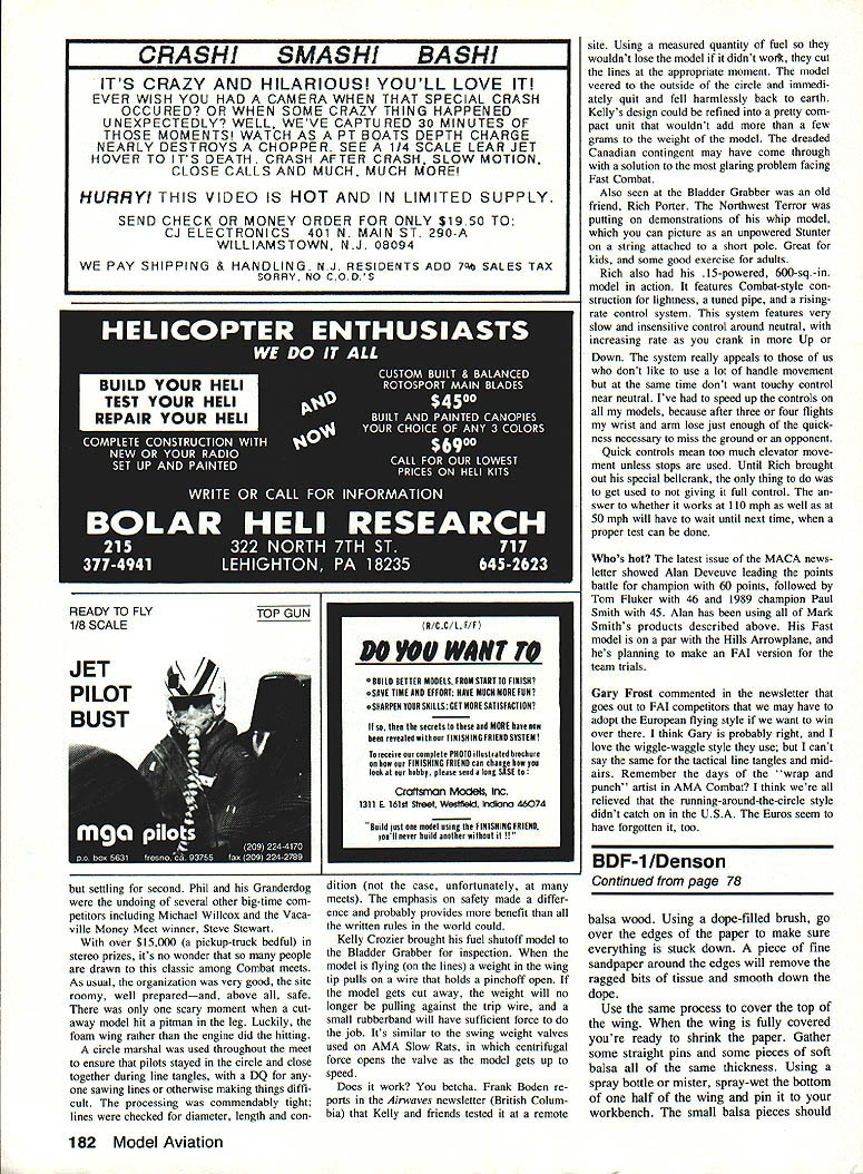
- Cement the wing pylon between formers F2 and F4 (not on F3) and brace it with 1/4‑in. triangular stock.
- A 1/4‑in. triangular strip under the leading edge adds incidence.
- After spraying with water and applying paint dope, mount wing blocks and pin the wing to the workbench so air can circulate and the assembly dries and does not warp.
Final Fitting and Engine Installation
- Check fit of firewall and wing; add any needed doublers or fillets and sand smooth.
- The firewall is set up to give the correct downthrust; you must add side thrust. When bolting the engine to the firewall, place a couple of washers between the back of the engine and the firewall on the left side (as viewed from the pilot) to produce the required side thrust.
- Drill the fuel tank hole carefully—its location is important. The hole must pass between the two bolts that hold the backplate and tank to the crankcase. If you misplace the hole, you may end up drilling a second one.
- We modified a medicine dropper as a tank: heated glass tubing and stretched the end so 1/4‑in. plastic tubing fits. Shorten the dropper, fasten it to a hardwood strip on the firewall, and secure with heat‑shrink tubing or small strips of tubing as required.
- Fill the medicine dropper tank with fuel, extract a bit into a syringe to prime the engine, wind the spring and launch when ready. Monitor fuel level and begin launch when the tank is nearly empty so the engine run is the correct length for retrieval.
Flying and Trim
- Do NOT launch the BDF-1 with a full tank of fuel—an engine run that long will put the plane out of sight overhead.
- Center‑of‑gravity: as marked on the plans (about two‑thirds of the wing chord). Check before first flight.
- Choose a calm day and a flat, soft field. Hold the plane over your head, walk or run until it wants to lift, then launch forward and level.
- If the plane floats straight, drops slowly and rolls to a stop, it’s perfect. If it dives or stalls, change wing incidence using strips of 1/16‑in. sheet balsa cracked to match the dihedral:
- If the plane dives, place spacers under the forward edge of the wing.
- If it stalls, place spacers under the trailing edge.
- Typical flight sequence: as the plane picks up speed it will climb in a right spiral (engine right trim), then when the engine quits it will slow and the rudders will take over, turning into a left spiral glide and floating down.
- Trimming:
- Make small incremental changes.
- If the plane initially climbs and then goes into a steep right bank, resist overcorrecting with too much left rudder (which can cause a left spiral).
- A small tab on the right wing tip (cardboard or light aluminum) bent down a little prevents a right spiral; the same effect can be achieved with wash‑in on the wing. We trim the left rudder very slightly and leave the right rudder neutral.
- A few test flights will give you a feel for timing the launch and further fine trimming.
Conclusion
The BDF-1 blends the old stick‑and‑tissue thrills with some modern building tips. It’s a fine project for novices moving up from wind‑ups or for experienced RC pilots wanting a change of pace. With careful building, careful trimming and modest fuel runs, it will repay you with delightful, nostalgic flights.
Transcribed from original scans by AI. Minor OCR errors may remain.

