
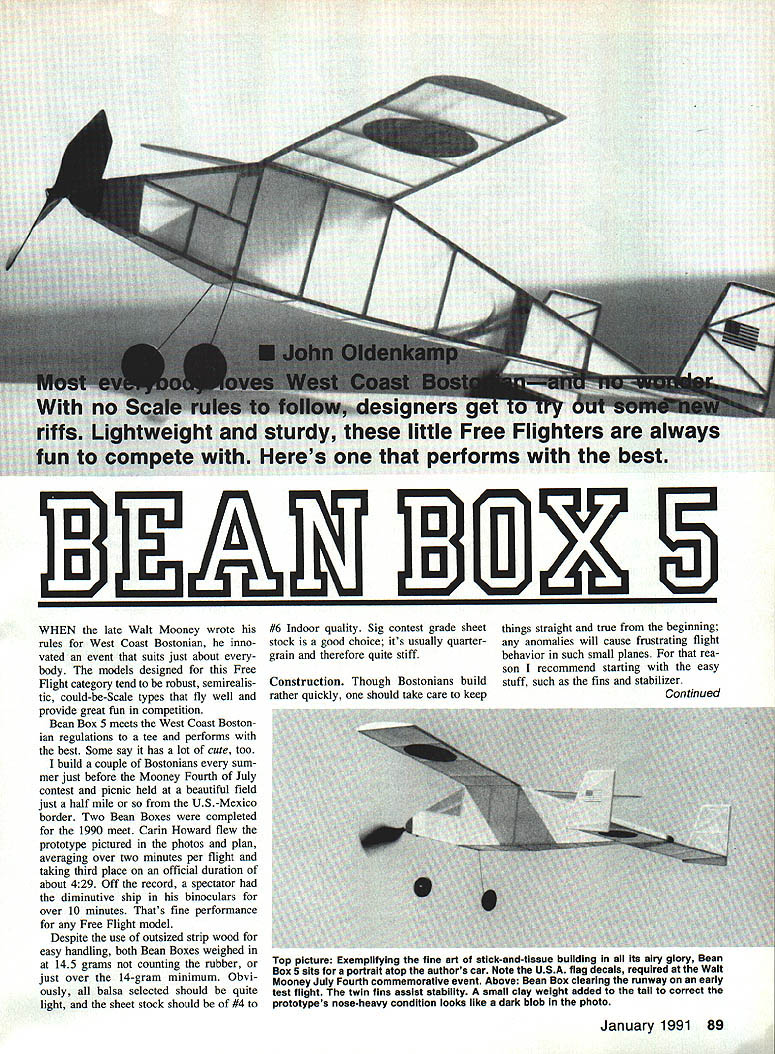
John Oldenkamp
BEAN BOX 5
When the late Walt Mooney wrote his rules for West Coast Bostonians, he invented an event that suits just about everybody. The models designed for this Free Flight category tend to be robust, semi-realistic, could-be-scale types that fly well and provide great fun in competition.
Bean Box 5 meets the West Coast Bostonian regulations to a tee and performs with the best. Some say it has a lot of cute, too. I build a couple of Bostonians every summer just before the Mooney Fourth of July contest and picnic held at a beautiful field a half mile or so from the U.S.–Mexico border. Two Bean Boxes were completed for the 1990 meet. Carin Howard flew the prototype pictured in the photos and plan, averaging over two minutes per flight and taking third place on an official duration of about 4:29. Off the record, a spectator had the diminutive ship in his binoculars for over 10 minutes. That's fine performance for any Free Flight model.
Despite the use of outsized strip wood for easy handling, both Bean Boxes weighed in at 14.5 grams not counting the rubber, or just over the 14-gram minimum. Obviously, all balsa selected should be quite light, and the sheet stock should be of #4 to #6 indoor quality. Sig contest-grade sheet stock is a good choice; it's usually quarter-grain and therefore quite stiff.
Construction
Though Bostonians build rather quickly, take care to keep things straight and true from the beginning; any anomalies will cause frustrating flight behavior in such small planes. For that reason I recommend starting with the easy stuff, such as the fins and stabilizer.
Fins and stabilizer
Use the softest wood available for these components. Begin by inserting pins around the outlines with the help of a straightedge, then fit and attach the major elements using Hot Stuff or a similar thin CyA (cyanoacrylate) glue. Carefully cut and fit the diagonals; they should be finger tight but no more, lest warps develop later.
Wing
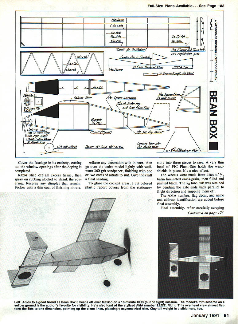
Prepare a thin plywood rib template with notches and registration pins as shown on the plan. To produce rib sets, simply press the template on the balsa stock, run a single-edged razor blade around the outline, then nick off the ends and notches with a chopping action. Cut the tip and center ribs from medium 1/16" sheet, the remainder from either 1/32" or 3/32" sheet.
Pin down the leading edge, then trap the ribs in place along the trailing edge stock. Raise the ribs in the washout area as indicated, and angle the center ribs for dihedral. Use the template shown on the plan.
When you're satisfied with the alignment, glue each rib station with CyA. Add the top spars and tip braces from 1/16" x 3/32" strip wood.
At this point the flying surfaces can be finished and prepared for covering. With a sanding block and 220-grit paper, smooth all flat areas and round the edges of the fin and stabilizer at the front and rear. Be sure to create the gentle upsweep on the leading-edge bottom, since it's a necessary part of the design.
Carefully cut the wing panel, then smooth out the center bevel. Prop each tip up 1/4", pin the center ribs together, and glue them firmly with a few drops of thin CyA.
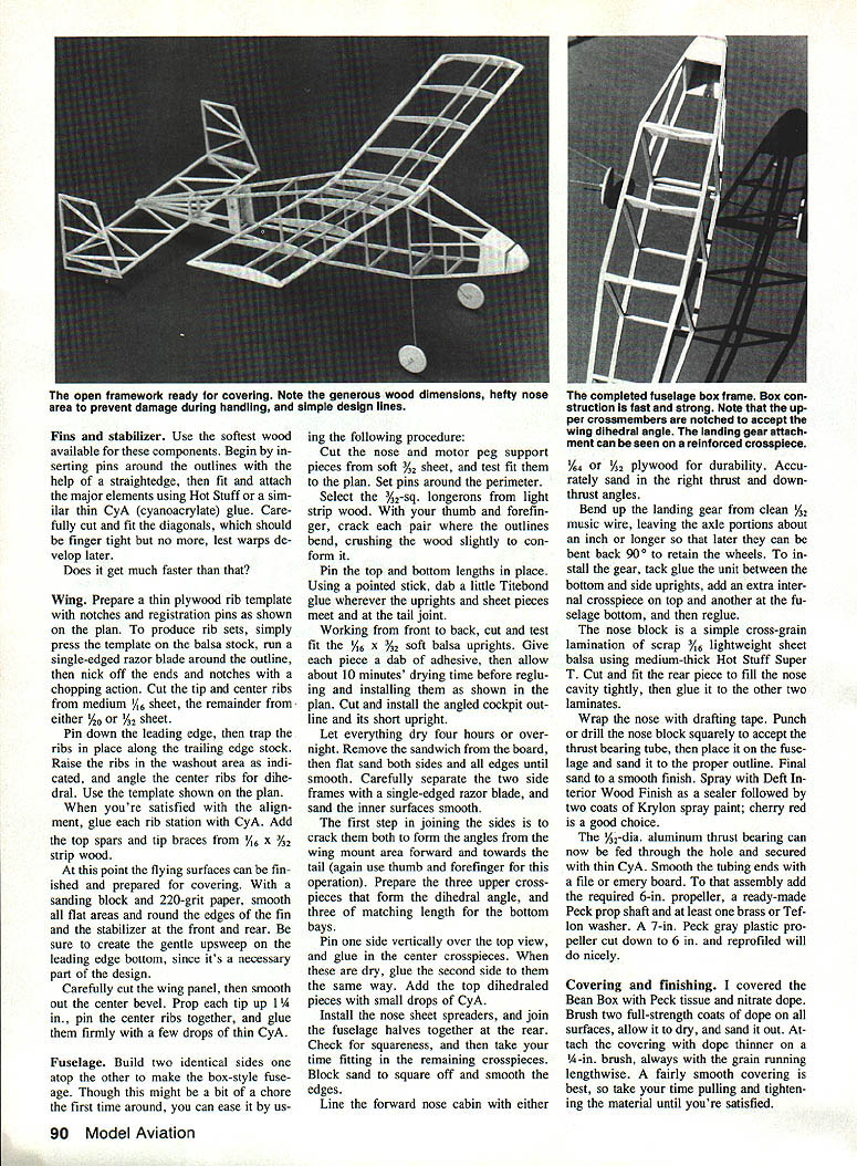
Fuselage
Build two identical sides atop one another to make the box-style fuselage. Though this might be a bit of a chore the first time around, you can ease it by using the following procedure.
Cut the nose and motor-peg support pieces from soft 3/32" sheet, and test-fit them to the plan. Set pins around the perimeter. Select the 3/32"-sq longerons from light strip wood. With your thumb and forefinger, crack each pair where the outlines bend, crushing the wood slightly to conform it.
Pin the top and bottom lengths in place. Using a pointed stick, dab a little Titebond glue wherever the uprights and sheet pieces meet at the tail joint.
Working from front to back, cut and test-fit 1/16" x 3/32" soft balsa uprights. Give each piece a dab of adhesive, then allow about 10 minutes' drying time before regluing and installing as shown on the plan. Cut and install the cockpit outline and its short upright.
Let everything dry four hours or overnight. Remove the sandwich from the board, then flat-sand both sides and all edges until smooth. Carefully separate the two side frames with a single-edged razor blade, and sand the inner surfaces smooth.
The first step in joining the sides is to crack them both to form the angles from the wing-mount area forward and toward the tail (again, use thumb and forefinger for this operation). Prepare the three upper crosspieces that form the dihedral angle, and three of matching length for the bottom bays.
Pin one side vertically over the top view, and glue in the center crosspieces. When these are dry, glue the second side to them the same way. Add the top dihedral pieces with small drops of CyA.
Install the nose-sheet spreaders, and join the fuselage halves together at the rear. Check for squareness, and then take your time fitting in the remaining crosspieces. Block-sand to square off and smooth the edges.
Line the forward nose cabin with either 1/16" or 1/32" plywood for durability. Accurately sand in the right thrust and down-thrust angles.
Bend up the landing gear from clean 1/32" music wire, leaving the axle portions about an inch or longer so that later they can be bent back 90° to notch the wheels. To install the gear, tack-glue the unit between the bottom and side uprights, add an extra internal crosspiece on top and another at the fuselage bottom, and then reglue.
The nose block is a simple cross-grain lamination of scrap 3/16" lightweight sheet balsa using medium-thick Hot Stuff. Cut and fit the rear piece to fill the nose cavity tightly, then glue it to the other two laminates.
Wrap the nose with drafting tape. Punch or drill the nose block squarely to accept the thrust-bearing tube, then place it on the fuse and sand it to the proper outline. Final sand to a smooth finish. Spray with Deft Interior Wood Finish as a sealer followed by two coats of Krylon spray paint; cherry red is a good choice.
The 1/32"-dia. aluminum thrust bearing can now be fed through the hole and secured with thin CyA. Smooth the tubing ends with a file or emery board. To that assembly add the required 6" propeller, a ready-made Peck prop shaft and at least one brass or Teflon washer. A 7" Peck gray plastic propeller cut down to 6" and reprofiled will do nicely.
Covering and finishing
I covered the Bean Box with Peck tissue and nitrate dope. Brush two full-strength coats of dope on all surfaces, allow it to dry, and sand it smooth. Attach the covering with dope thinner on a 1/4" brush, always with the grain running lengthwise. A fairly smooth covering is best, so take your time pulling and tightening the material until you're satisfied.
Cover the fuselage in its entirety, cutting out the window openings after the doping is completed. Razor-slice off all excess tissue, then spray on rubbing alcohol to shrink the covering. Respray any dimples that remain. Follow with a thin coat of finishing nitrate.
Adhere any decoration with thinner, then go over the entire model lightly with well-worn 360-grit sandpaper, finishing with one or two coats of nitrate to suit. Give the craft a final sanding.
To glaze the cockpit areas, cut colored plastic report covers from the stationery store into three pieces to size. A very thin bead of PIC Plasti-Stic holds the window shields in place — it's a nice effect.
The wheels were made from discs of 1/16" balsa laminated cross-grain, then filled and painted black. The 1/32" tube hub was retained by bending the axle ends back parallel to flight direction and snipping them off.
Add the AMA number, flag decal, and name-and-address identification before final assembly.
Final assembly
After carefully scraping away tissue wherever parts are meant to join, trial-fit and CyA the rudders to the stabilizer and the wing to the fuselage. Since this is a locked-in machine, I deliberately skewed the stabilizer/rudder unit to give a left glide turn, making the offset about 1/8" through the stabilizer span. No tilt was used.
Before adding full beads of CyA, be certain that all alignments are as precise as you can get them, whether by eyeballing or measuring. Take your time!
At this point the model should be almost ready for flight. All that remains is to drill out the motor-peg hole — a bamboo skewer makes a fine tool for this purpose — and to double-check (and admire!) your work.
Early in flight testing it was clear that Bean Box had a sound pedigree and more than a little potential. Flight times climbed from scant seconds to well over five minutes' duration, and the model showed an uncanny ability to ride out light morning thermals.
Some initial disappointments had to be counteracted. When the plane didn't climb as high as expected, I put a small wad of clay on the tail. When it went straight under power, I shimmed in more right thrust. When it occasionally stalled under full winds, I used more downthrust. Those are the only adjustments available on a locked-in airplane, so it makes sense to know them well.
No glide tests were done. Since it's nearly impossible to predict a small model's behavior until it's up there amongst 'em, there's little sense in risking a bent prop shaft before the first flight.
Both Bean Boxes ran on two strands of RAF 1/8 x 1/4-inch rubber, using a maximum of about 1,100 turns. A blast tube is highly recommended, as is a nonplush rubber lube to help keep your masterpiece clean. I've found that an STP spray product called Son of a Gun works really well and I use it exclusively. Saturate the motor and leave it out overnight. Pat off the excess with a paper towel, and your motor's ready to go.
Epilogue
Because both prototypes eventually rode away in strong (but undetected) lift, I'm considering including dethermalizing hardware in the next batch. But I'd have to shave off some weight elsewhere in the model to work it in. I'll probably also separate the wing for positive action.
Transcribed from original scans by AI. Minor OCR errors may remain.

