
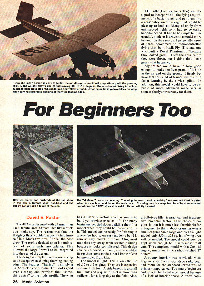
THE 4B2 (For Beginners Too) was designed to incorporate all the flying requirements of a basic trainer and put them into a reasonably sized package that would be pleasing to look at. Many of us fly from unimproved fields so it had to be easily hand-launched. It had to be simple but unusual. A modeler is drawn to a model more by emotion than reason. I personally know of three newcomers to radio-controlled flying that built Kwik-Fly III's and one who built a Royal Phantom II "because they looked great." I left the area before they were flown, but I think that I can guess what happened.
My trainer would have to look good enough to make the flyer proud of it both in the air and on the ground. I firmly believe that this kind of trainer will result in faster learning by the novice "pilot." In addition, this model would have to be capable of more advanced maneuvers as soon as the flyer was ready for them.
For Beginners Too
David E. Pastor
The 4B2 was designed with a larger than usual frontal area. Streamlined like a brick you might say. The reason was that the fledgling flyer wouldn't suddenly find himself in a Mach-two dive if he let the nose drop. The profile decided upon is reminiscent of some early monoplanes. This allowed the large firewall to be integrated into the rest of the design.
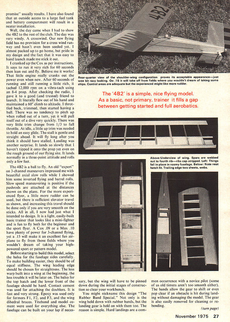
The design is simple. There is no carving to do except when shaping the wing leading edge. The headrest "fairing" is simply a 3/16" thick piece of balsa. This looks good even close-up and provides that "something extra" to the model profile. The wing has a Clark Y airfoil which is simple to build yet provides excellent lift. Too many beginners get tied down building their first model when they could be learning to fly it. This model can be ready for finishing in a very few hours. An easy model to build is also an easy model to repair. Also, most modelers shy away from scratch-building because it looks complicated. This design can be carved, cut out, and assembled faster than some models that I know of can be assembled from kits.
The model is light. This allows the use of .10 to .15 engines. They are inexpensive and use little fuel. A side benefit is a small fuel tank and a quart of fuel is more than sufficient for a long day at the field. Also, a bulb-type filler is practical and inexpensive. No small factor in this choice of engines is that it is much less formidable for a beginner to think about cranking over a small engine than a large one. With a light model, only 350 to 375 sq. in. of wing area will be needed. The model could now be kept small enough to fit into most small cars. The completed model with a Cox .15 engine, minus only the radio, weighed 27 ounces.
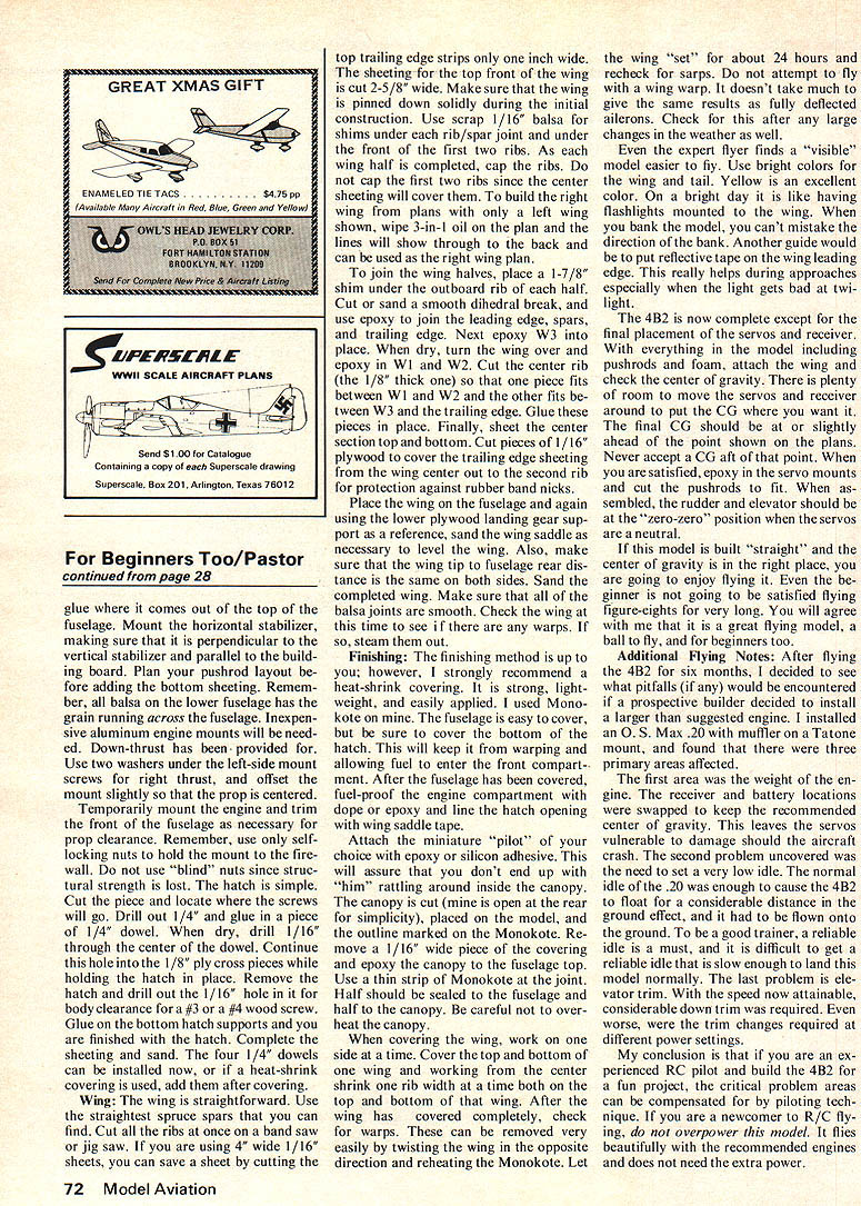
A roomy interior was provided. Most beginners start with sport-type radio gear and room for the standard servos was of primary importance. Too many beginners end up badly balanced model because of a lack of interior space. I have also found that an outside access to a large fuel tank and battery compartment will result in a neater installation.
Well, the day came when I had to show the 4B2 to the rest of the club. The day was very windy. A crosswind. Our new flying field has no provision for a cross wind runway and hasn't even been seeded yet. I almost packed up to go home, but pride in my design and the fact that it was easy to hand launch made me stick it out.
I cranked up the Cox as per instructions. It says to run it very rich for 60 seconds then lean out and fly. Believe me it works! That little engine really cranks out the power even when new. After 60 seconds of running and still running a little rich, it tached 12,000 rpm on a vibra-tach using an 8-4 prop. After checking the radio, I gave it to a good (and trusted) friend to launch. It literally flew out of his hand and maintained a 60° climb to altitude. I throttled back, trimmed, then started having a ball. There was no tendency to pitch up when rolled out of a turn, yet it will pull itself out of a dive very quickly. There was very little trim change from 1/3 to full throttle. At idle, a little up trim was needed to hold an easy glide. The stall is gentle and straight ahead. It will fly long after you think it should have stalled. Landing was another surprise. It lands so slowly that I haven't tipped it onto the prop yet even on the rough ground of our flying site. It lands normally in a three-point attitude and rolls only a few feet.
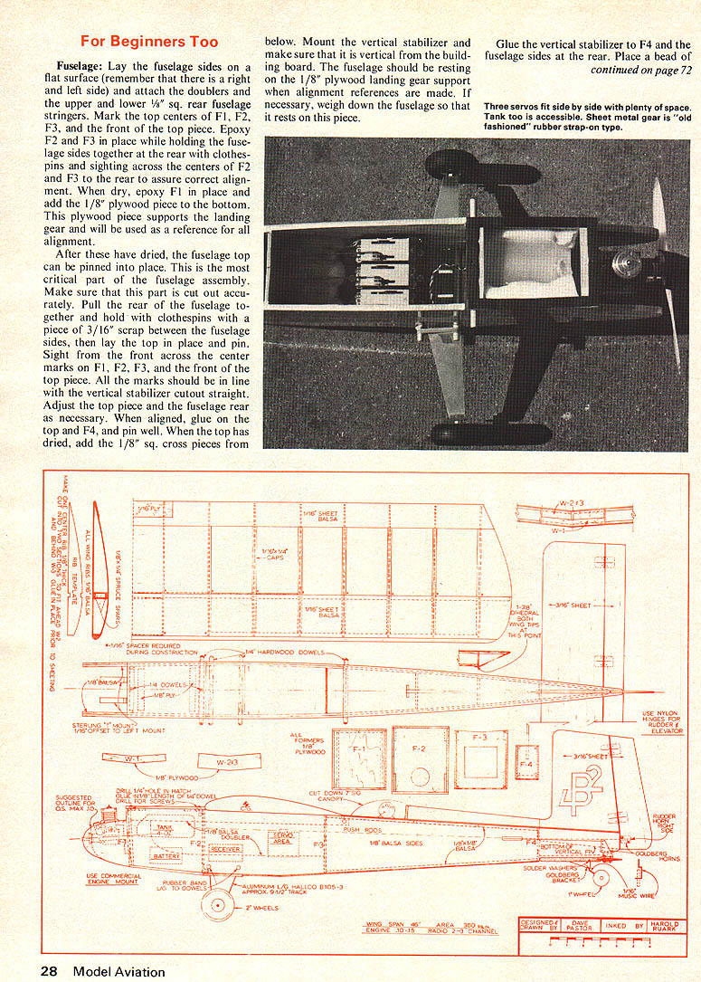
The 4B2 is a ball to fly. An old "expert" on 3-channel maneuvers impressed me with beautiful axial slow rolls while I showed him some inverted flying and barrel rolls. Slow speed maneuvering is positive if the pushrods are attached at the distances shown on the plans. For the more experienced flyer, a little more rudder can be used, but there is sufficient elevator travel as shown, and increasing this travel should be done only if you are very smooth on the sticks. All in all, I now had just what I intended to design. It is a light, easily-built basic trainer that looks like a mini-fighter and is fun to fly both for the beginner and the sport flyer. A Cox .09 or a Max .10 have plenty of power for 3-channel flying, yet a .15 will make it an excellent fun airplane to fly from those fields where you wouldn't dream of taking your high-powered sport or pattern model.
Before starting to build this model, select the balsa for the fuselage sides carefully. To make building easier, they should be of equal stiffness. The wing leading edge should be chosen for straightness. The less warp built into a wing at the beginning, the less trouble it will be later on. The balsa for the top hatch and the lower front of the fuselage should be hard. Contact cement was used for attaching the doublers. It is fast and very strong. Epoxy was used only for formers F1, F2, and F3, and the wing dihedral braces. Titebond and model cement were used for everything else. The fuselage can be built on your lap if necessary, but the wing will have to be pinned down during the initial stages of construction so clear your workbench.
You might nickname this design "The Rubber Band Special." Not only is the wing held down with rubber bands, but the landing gear is held on with them too. The reason is simple. Hard landings are a common occurrence with a novice pilot (some of us old timers aren't too smooth either). The bands allow the gear to shift or even pop clear if an obstacle is hit during landing without damaging the model. The gear is also easily removed for cleaning or rebending. Fuselage: Lay the fuselage sides on a flat surface (remember that there is a right and left side) and attach the doublers and the upper and lower 1/8" sq. rear fuselage stringers. Mark the top centers of F1, F2, F3, and the front of the top piece. Epoxy F2 and F3 in place while holding the fuselage sides together at the rear with clothespins and sighting across the centers of F2 and F3 to the rear to assure correct alignment. When dry, epoxy F1 in place and add the 1/8" plywood piece to the bottom. This plywood piece supports the landing gear and will be used as a reference for all alignment.
After these have dried, the fuselage top can be pinned into place. This is the most critical part of the fuselage assembly. Make sure that this part is cut out accurately. Pull the rear of the fuselage together and hold with clothespins with a piece of 3/16" scrap between the fuselage sides, then lay the top in place and pin. Sight from the front across the center marks on F1, F2, F3, and the front of the top piece. All the marks should be in line with the vertical stabilizer cutout straight. Adjust the top piece and the fuselage rear as necessary. When aligned, glue on the top and F4, and pin well. When the top has dried, add the 1/8" sq. cross pieces from below. Mount the vertical stabilizer and make sure that it is vertical from the building board. The fuselage should be resting on the 1/8" plywood landing gear support when alignment references are made. If necessary, weigh down the fuselage so that it rests on this piece.
Glue the vertical stabilizer to F4 and the fuselage sides at the rear. Place a bead of glue where it comes out of the top of the fuselage. Mount the horizontal stabilizer, making sure that it is perpendicular to the vertical stabilizer and parallel to the building board. Plan your pushrod layout before adding the bottom sheeting. Remember, all balsa on the lower fuselage has the grain running across the fuselage. Inexpensive aluminum engine mounts will be needed. Down-thrust has been provided for. Use two washers under the left-side mount screws for right thrust, and offset the mount slightly so that the prop is centered.
Temporarily mount the engine and trim the front of the fuselage as necessary for prop clearance. Remember, use only self-locking nuts to hold the mount to the firewall. Do not use "blind" nuts since structural strength is lost. The hatch is simple. Cut the piece and locate where the screws will go. Drill out 1/4" and glue in a piece of 1/4" dowel. When dry, drill 1/16" through the center of the dowel. Continue this hole into the 1/8" ply cross pieces while holding the hatch in place. Remove the hatch and drill out the 1/16" hole in the fuselage clearance for a #3 or a #4 wood screw. Glue on the bottom hatch supports and you are finished with the hatch. Complete the sheeting and sand. The four 1/4" dowels can be installed now, or if a heat-shrink covering is used, add them after covering.
Wing: The wing is straightforward. Use the straightest spruce spars that you can find. Cut all the ribs at once on a band saw or jig saw. If you are using 4" wide 1/16" sheets, you can save a sheet by cutting the top trailing edge strips only one inch wide. The sheeting for the top front of the wing is cut 2-5/8" wide. Make sure that the wing is pinned down solidly during the initial construction. Use scrap 1/16" balsa for shims under each rib/spar joint and under the front of the first two ribs. As each wing half is completed, cap the ribs. Do not cap the first two ribs since the center sheeting will cover them. To build the right wing, form plans with only a left wing shown, wipe 3-in-1 oil on the plan and the lines will show through to the back and can be used as the right wing plan.
To join the wing halves, place a 1-7/8" shim under the outboard rib of each half. Cut or sand a smooth dihedral break, and use epoxy to join the leading edge, spars, and trailing edge. Next epoxy W3 into place. When dry, turn the wing over and epoxy in W1 and W2. Cut the center rib (the 1/8" thick one) so that one piece fits between W1 and W2 and the other fits between W3 and the trailing edge. Glue these pieces in place. Finally, sheet the center section top and bottom. Cut pieces of 1/16" plywood to cover the trailing edge sheeting from the wing center out to the second rib for protection against rubber band nicks.
Place the wing on the fuselage and again using the lower plywood landing gear support as a reference, sand the wing saddle as necessary to level the wing. Also, make sure that the wing tip to fuselage rear distance is the same on both sides. Sand the completed wing. Make sure that all of the balsa joints are smooth. Check the wing at this time to see if there are any warps. If so, steam them out.
Finishing: The finishing method is up to you; however, I strongly recommend heat-shrink covering. It is strong, lightweight, and easily applied. I used Monokote on mine. The fuselage is easy to cover, but be sure to cover the bottom of the hatch. This will keep it from warping and allowing fuel to enter the front compartment. After the fuselage hatch has been covered, fuel-proof the engine compartment with dope or epoxy and line the hatch opening with saddle tape.
Attach the miniature "pilot" of your choice with epoxy or silicone adhesive. This will insure that you don't end up with "him" rattling around inside the canopy. The canopy is cut (mine is open at the rear for simplicity), placed on the model, and the outline marked on the covering. Remove a 1/16" wide strip of covering at the canopy joint. Use a thin strip of Monokote at the joint. Half should be sealed to the fuselage and half to the canopy. Be careful not to overlap the canopy.
When covering the wing, work on one side at a time. Cover the top and bottom of the wing panels, working from the center out one rib at a time. After the wing has been covered completely, check for warps. If warps exist, they can be removed very easily by twisting the wing in the opposite direction and reheating the Monokote. Let the wing "set" for about 24 hours and recheck for warps. Do not attempt to fly with a wing warp. It doesn't take much to give the same results as fully deflected ailerons. Check for this after any large changes in the weather as well.
Even the expert flyer finds a "visible" model easier to fly. Use bright colors for the wing and tail. Yellow is an excellent color. On a bright day it is like having flashlights mounted to the wing. When you bank the model, you can't mistake the direction of the bank. Another guide would be to put reflective tape on the wing leading edge. This really helps during approaches, especially when the light gets bad at twilight.
The 4B2 is now complete except for the final placement of the servos and receiver. With everything in the model including pushrods and foam, attach the wing and check the center of gravity. There is plenty of room to move the servos and receiver around to put the CG where you want it. The final CG should be at or slightly ahead of the point shown on the plans. Never accept a CG aft of that point. When you are satisfied, epoxy in the servo mounts and cut the pushrods to fit. When assembled, the rudder and elevator should be at the "zero-zero" position when the servos are neutral.
If this model is built "straight" and the center of gravity is in the right place, you are going to enjoy flying it. Even the beginner is not going to be satisfied flying figure-eights for very long. You will agree with me that it is a great flying model, and not only for beginners too.
Additional Flying Notes: After flying the 4B2 for six months, I decided to see what pitfalls (if any) would be encountered if a prospective builder decided to install a larger than suggested engine. I installed an O.S. Max .20 with muffler on a Tatone mount, and found that there were three primary areas affected.
The first area was the weight of the engine. The receiver and battery locations were swapped to keep the recommended center of gravity. This leaves the servos vulnerable to damage should the aircraft crash. The second problem uncovered was the need to set a very low idle. The normal idle of the .20 was enough to cause the 4B2 to float for a considerable distance in ground effect, and it had to be flown onto the ground. To be a good trainer, a reliable idle is a must, and it is difficult to get a reliable idle that is slow enough to land this model normally. The last problem is elevator trim. With the speed now attainable, considerable down trim was required. Even worse, there were trim changes required at different power settings.
My conclusion is that if you are an experienced R/C pilot and build the 4B2 for fun as a project, the critical problem areas can be compensated for by piloting technique. If you are a newcomer to R/C flying, don't overpower this model. It flies beautifully with the recommended engines and does not need the extra power.
Transcribed from original scans by AI. Minor OCR errors may remain.

