
Beliaev's Winner
Background
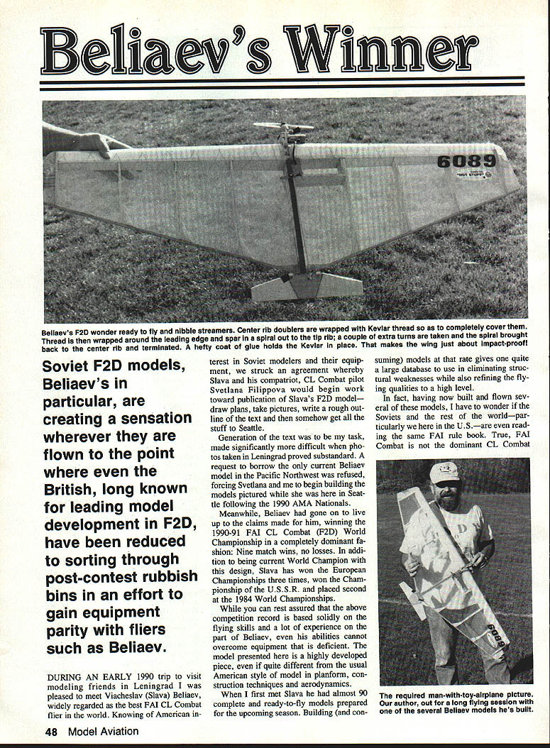
Soviet F2D models—Beliaev's in particular—are creating a sensation wherever they are flown. Even British fliers, long known for leading model development in F2D, have been reduced to sorting through post-contest rubbish bins to gain equipment parity with fliers such as Viacheslav (Slava) Beliaev.
During an early 1990 trip to Leningrad I met Slava Beliaev, widely regarded as the best FAI CL Combat (F2D) flier in the world. Knowing of American interest in Soviet models and equipment, Slava and compatriot CL Combat pilot Svetlana Filippova agreed to prepare plans, photos and a rough text outline for publication and get the material to Seattle. Generating the final text proved difficult: photos taken in Leningrad were substandard and a request to borrow the only current Beliaev model in the Pacific Northwest was refused, so Svetlana and I built the pictured models in Seattle after the 1990 AMA Nationals.
Beliaev lived up to his reputation by winning the 1990–91 FAI CL Combat (F2D) World Championship in dominant fashion: nine match wins, no losses. He has also won the European Championships three times, the Championship of the U.S.S.R., and placed second at the 1984 World Championships. His record rests on outstanding flying skill and extensive experience, but the equipment presented here is also a major factor.
Beliaev had nearly 90 complete, ready-to-fly models prepared for a season. Building at that rate provides a large database for eliminating structural weaknesses and refining flying qualities. The design presented is highly developed—quite different from usual American models in planform, construction techniques and aerodynamics.
Design Features
- The model favors rugged, repeatable construction over exotic materials. Kevlar thread reinforcement is used; carbon fiber is available in the Soviet Union but is little used here.
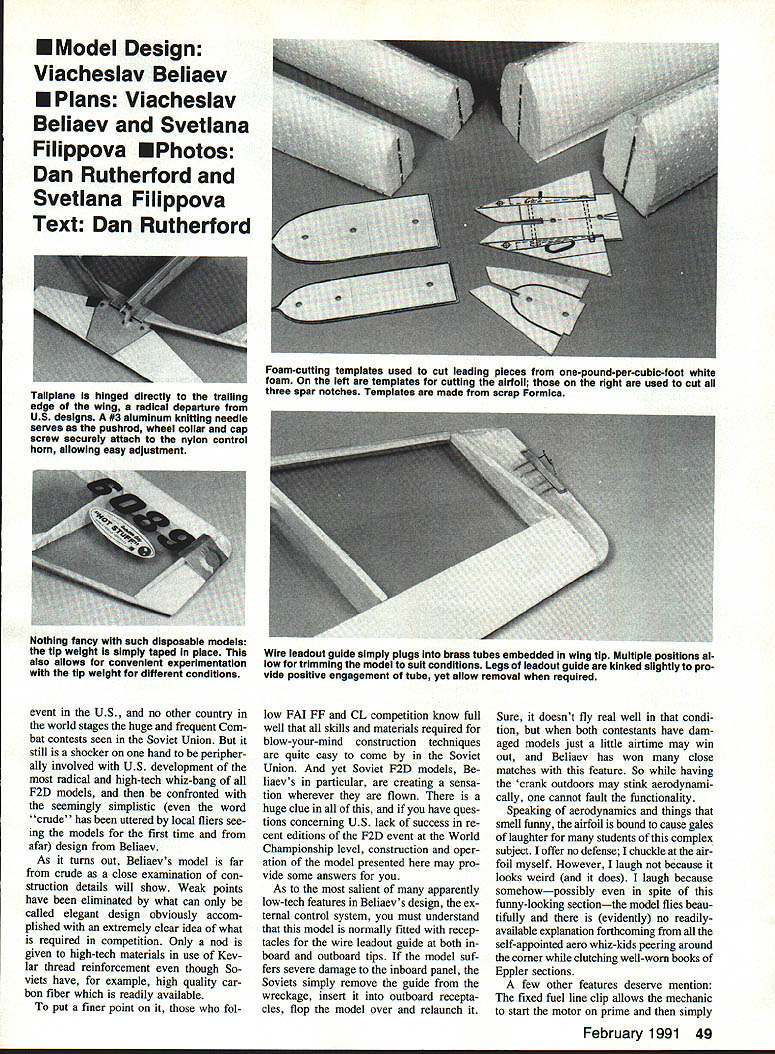
- External control system: receptacles and a wire leadout guide are fitted at both inboard and outboard tips. If the inboard guide is wrecked, the Soviets remove it, insert the outboard receptacle, flip the model and relaunch. Aerodynamically suboptimal, but highly functional in match situations.
- Airfoil: unconventional and often laughed at by aero students, yet it flies beautifully. Experience proves its effectiveness despite its odd appearance.
- Practical pit features: fixed fuel-line clip for quick starts, underside-mounted streamer clip to keep pit work on one side, and taped-on tip/tail weights for quick trim changes.
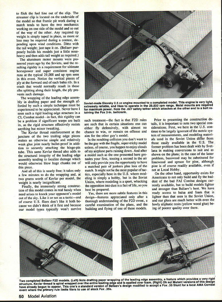
- Aluminum motor mounts provide rigidity required for consistent high-rpm engine runs.
- Vertical pieces of 1/32-in. ply at the forward end of each balsa rib prevent ribs splitting in a crash.
- Leading-edge wrapped in drafting paper produces exceptional rigidity.
- Kevlar wrapping at trailing-edge joints and hinge-pin juncture makes otherwise weak glue joints nearly bullet-proof.
The design emphasizes impact resistance because collisions and intentional "whacking" of opponents' models are a common tactic in Soviet F2D competition. A fragile, super‑tricky model is disadvantaged when physical contact occurs.
Construction
Note: Soviet measurements and materials differ from those found in the U.S. Svetlana converted dimensions to U.S. practice. Basswood may substitute for limewood and spruce for pine where appropriate.
Templates and Spars
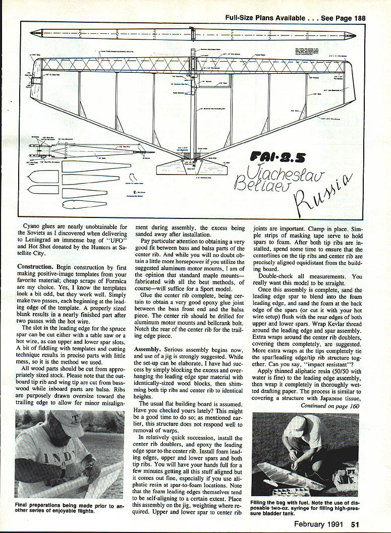
- Make positive-image templates from a stable material (Formica recommended).
- Cut foam parts with a hot wire; two passes beginning at the leading edge produce a properly sized blank.
- Cut the slot in the spruce spar (table saw or hot wire). Upper and lower spar slots can be cut the same way.
- Use appropriately sized stock for all wood parts:
- Outboard tip rib and wing tip: basswood.
- Inboard parts: balsa.
- Ribs purposely drawn oversize toward the trailing edge to allow for alignment sanding after assembly.
- Pay attention to the fit between bass and balsa parts of the center rib.
Center Rib
- Glue the center rib complete, ensuring a very good epoxy joint between the bass front end and the balsa piece.
- Drill the center rib for aluminum motor mounts and the bellcrank bolt.
- Notch the rear of the center rib for the trailing-edge joiner.
- Install center rib doublers and plan for Kevlar wrapping later.
Assembly (use a jig)
- Use a jig or a simple block-and-shim setup to get identical heights for tip ribs and the center rib.
- Check that the building board is level; the structure resists correction of warps once built.
- Epoxy the leading-edge spar to the center rib, then install foam leading edges, upper and lower spars and both tip ribs. Masking tape can hold spars to foam temporarily.
- Align centerlines on the tip ribs and center rib so they are equidistant from the building board.
- Clamp and allow glue to cure; double-check straightness.
Leading Edge
- Sand the leading-edge spar to blend into the foam leading edge. Trim the foam flush with the rear edges of the spars.
- Wrap Kevlar thread around the leading edge and spar assembly. Extra wraps are advised at the tips and center-rib doublers.
- Apply thinned aliphatic resin (50/50 with water is fine) to the leading-edge assembly, then wrap completely in wetted drafting paper (similar to covering with Japanese tissue). Drafting paper is tough and available in large sheets; other light papers may work in a pinch.
- Hold the assembly aligned while drying. Use wing tips with wood blocks, weights and shims to maintain geometry.
- The paper-wrapped leading edge gains maximum rigidity after the wrap cures.
Trailing Edge and Ribs
- Assemble the trailing-edge pieces to the center joiner and hinge-pin tubing; sand trailing edges to a slight taper (not razor sharp).
- With the framework in the jig, glue the trailing-edge assembly to tip ribs and center rib.
- Install remaining ribs in each wing panel, glue all small gussets and doublers shown on the plans.
- Note the 1/32-in. vertical ply pieces between the nose of each rib and the leading-edge assembly.
- When dry, remove the wing from the jig, sand and fair joints, then sheet the lower wing surface with 1/32-in. balsa. Sand smooth and true.
- Install tubular hinge pins and check alignment in open and closed positions.
- Glue all gussets between the trailing edge and ribs. Thin cyano (Hot Stuff) is recommended for these joints.
Kevlar Wrap and Center Rib
- Install a 1/32-in. diameter wire common to the center rib upper and lower surfaces, extending from the bellcrank area to the trailing edge.
- Spiral-wrap Kevlar thread around the center-rib assembly with many wraps (10–12) directly behind the spars and immediately in front of the trailing-edge joiner. Tack-glue wraps with Hot Stuff as needed.
- Center-rib doublers wrapped with Kevlar thread cover the center rib completely. The Kevlar spirals out to the tip rib with extra turns and returns to the center rib where it is glued down. This makes the wing nearly impact-proof.
Bladder, Stab and Hinges
- Install the bladder compartment (two pieces of balsa) and epoxy-fuel-proof it completely.
- Carve the stab to shape by rounding edges; no special airfoil needed.
- Reinforce the elevator per Beliaev: .010-in. aluminum sheet attached with contact cement; 1/4-in. ply is an alternative.
- Cover the elevator with light plastic film. If you cannot find the Soviet nylon fittings, substitute Du-Bro 3/32-in. aileron wire bearings; they have proven reliable.
Controls and Hardware
- Motor mounts: aluminum mounts recommended for Sport and competition; well-made maple mounts are acceptable for lighter builds.
- The external control system uses receptacles at both tips for the wire leadout guides so outboard guides can be used if the inboard guide is wrecked.
- The bellcrank: a 2-in. Fox or Sig bellcrank spaced to 2-in. works. Beliaev uses a machined aluminum pin to retain the crank; 6-32 all-thread is an alternative.
- Pushrod: needs to be relatively stiff. A 3/32-in. aluminum knitting needle from a fabric store works well.
- A Du-Bro 1/8-in. wheel collar can accept the pushrod; secure it with a 4-40 setscrew to the control horn. Total elevator movement: start with no more than 1-1/4 in. for first flights; less is safer.
- Install engine-retaining wire attached to the bellcrank anchor.
Covering
- Paper-covered foam tolerates heat poorly, so choose coverings that won't damage foam. FasCal is acceptable but a bit heavy.
- Soviets use a one-mil Mylar-like material: light, tough, and not glue-heavy. They attach it with a thinned adhesive similar to automotive weather-stripping adhesive.
- A practical U.S. method: spray a light coating of 3M 77 Spray Adhesive on the ribs and glue points, then attach any heat-shrinkable film and shrink gently. Beliaev attaches covering only to ribs, center rib, trailing edges, around tip ribs, center-rib doublers, and a good coat along the leading-edge rub—no glue on the leading edge itself. Each panel is covered with one piece of film.
- Typical weights quoted: Soviet film ~23 g, Clearplane ~22 g. Covering adhesive as used above can be as little as 1 g.
- After covering, glue a piece of 1/64-in. ply to the covering over the bladder box and fuel-proof the motor-mount area.
Final Assembly and Setup
- Install elevator with control horn; retain hinge with a pin and tape during fitting.
- Install bellcrank and pushrod. Ensure the pushrod retention and adjustments are secure.
- Attach a high-performance 2.5 cc engine. The model is designed for 1° to 3° thrust offset to the outside of the circle; for first flights start with a couple degrees of offset.
- Check balance: the competition balance point is rather rearward for the performance delivered. For first flights, move the balance point 1/2 in. to 5/8 in. forward of the suggested position; add another 1/8 in. if you haven't flown in a while.
- If minor warps exist, correct them; the structure resists correction, so build straight from the start. Tape 5 grams to the outboard tip for the first flight if desired. Use .012 x 52-ft. lines for early flights (competition requires .015 x 52-ft. lines).
Flying and Performance
- Conduct initial test flights with a short fuel load.
- Focus early flights on whether the wings are level in upright and inverted flight.
- As you move the balance point rearward and increase elevator travel (toward the plan's setting), the model comes alive: very tight, high-speed loops and precision turning are possible.
- The model accelerates immediately out of cranked maneuvers with a high-revving 2.5 cc engine.
- Advanced maneuvers include progressively tightening loops, tight inside/outside loops of 3½–4 ft. diameter at very low altitude, and a host of combat- and show-oriented maneuvers (wiggles, squirgles, stairs, hooks, "S" turns with tiny half loops, etc.).
- The design's ruggedness is essential; collision survival is a real match consideration.
Beliaev sums up his design: "The construction of this model is simple enough to allow for easy building while also being extremely reliable in competition. I feel construction of the model as presented in this article is the best I have ever used. Happy flights to you."
Materials and Substitutions
- Basswood may substitute for limewood; spruce for pine.
- U.S. balsa and foam tend to be lighter than Soviet materials; better adhesives (cyanoacrylate, epoxy) are more readily available here.
- STELS-produced Gievsky 2.5 cc engines are what Beliaev commonly uses; similar high-performance 2.5 cc engines in North America are heavier but workable.
Acknowledgments
Thanks to Viacheslav Beliaev for freely supplying plans and information, and to Svetlana Filippova for converting and preparing the material for publication. Their cooperation made this article possible.
Technical Data
- Wingspan: 47 in.
- Total area (including tailplane): 532 sq. in.
- Model weight, less fuel: 16.8 oz. (15.5 oz. is better and achievable with U.S. foam, good wood and cyano glues; one 14.2-oz. model was built but was structurally marginal for competition)
- Wing loading: 4.55 oz. per sq. ft.
Transcribed from original scans by AI. Minor OCR errors may remain.

