
Bellanca Columbia
Dave Haught
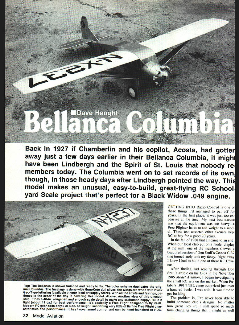
Back in 1927, if Clarence Chamberlin and his copilot Bert Acosta had gotten away just a few days earlier in their Bellanca Columbia, it might have been Lindbergh and the Spirit of St. Louis that nobody remembers today. The Columbia went on to set records of its own in those heady days after Lindbergh pointed the way. This model makes an unusually easy-to-build, great-flying RC schoolyard-scale project that's perfect for a Black Widow .049 engine.
Getting into Radio Control
Getting into radio control is one of those things I'd managed to put off for years. At first it was simply too expensive; then I told myself the equipment was too heavy—a Free Flighter hates added weight. These and assorted other excuses kept RC at bay for about 20 years.
In the fall of 1988 that all came to an end. At a local club model display one member showed a beautiful version of Don Srull's Cessna C-37 that immediately caught my eye. After finding and reading Srull's article in the November 1986 Model Aviation, I began investigating the small RC sets on the market. When Futaba's 4NBL came out priced just over a hundred bucks, I was sold. It was time to get building.
The radio would be getting a good workout in a glider, so my first scale RC would have to be a high-wing monoplane. I initially considered the Spirit of St. Louis, but there were concerns about nose moment and tail size—old Free Flight scale habits are hard to break. One night, watching the TV movie The Spirit of St. Louis, I saw a scene of Jimmy Stewart handling a Bellanca and knew the decision was made: the Columbia.
History
The Columbia was a specially built Bellanca with huge fuel capacity, designed to set duration and distance records. Owners Charles Levine and Clarence Chamberlin planned to fly nonstop from New York to Paris, but were beaten by Lindbergh by only a few days. Undaunted, the aviators modified their route and decided to go to Berlin.
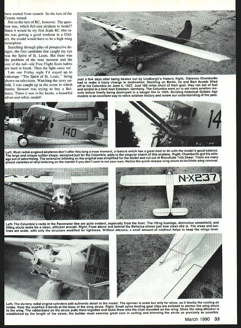
With fellow pilot Bert Acosta, Chamberlin crossed the Atlantic on June 4, 1927. Four thousand four hundred miles later the Columbia ran out of fuel and made a forced landing in a village called Helfta, just outside Eisleben (Eisleben), Germany. The aviators received a hero's welcome, and the Columbia went on to set more aviation records before finally being destroyed in a hangar fire in New Castle, Pennsylvania, in 1935.
Building historical Golden Age models is an excellent way to relive aviation history and renew our understanding of the past.
Photos and notable details
- Left: The Columbia's roots in the Pacemaker line are evident—especially the front lifting fuselage and distinctive windshield. Lifting struts make for a clean, efficient aircraft.
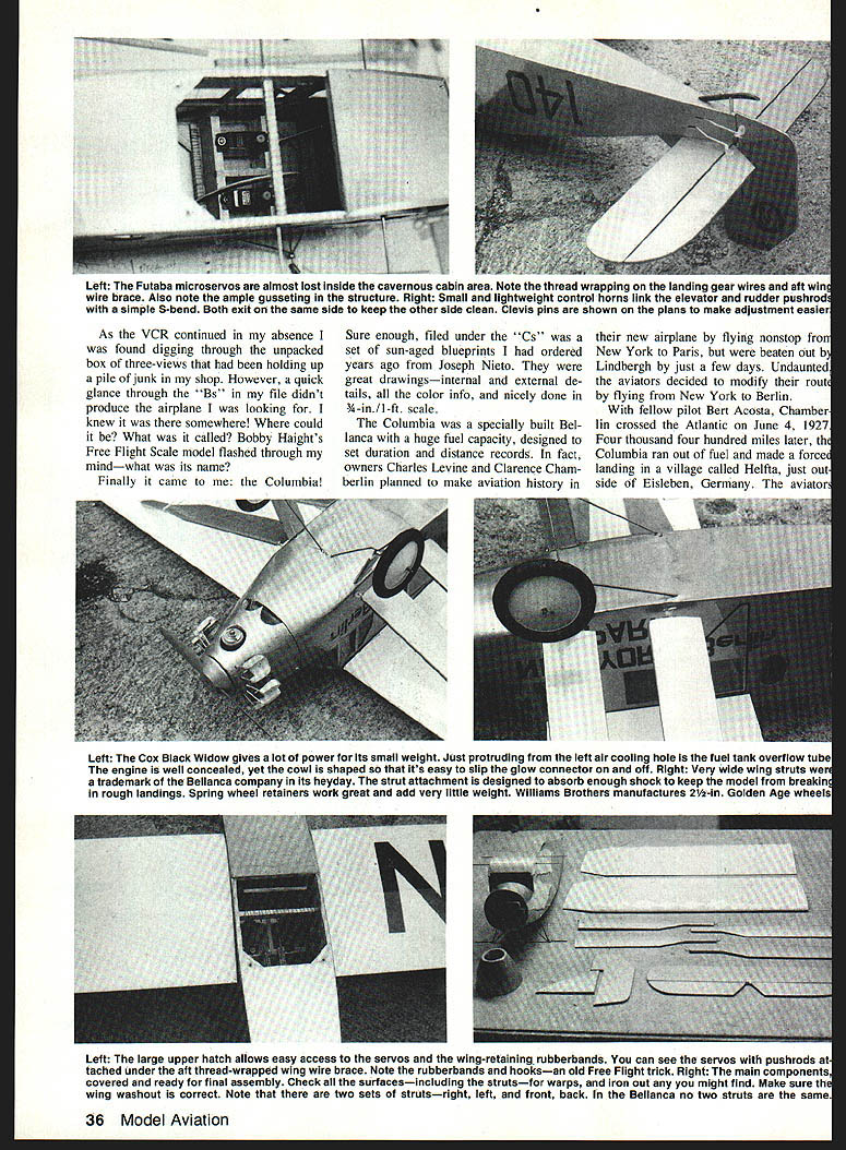
- Right above: Bellanca shows clean, out-scale structure modified for lightness. Without ailerons, a small amount of washout helps keep the wings level.
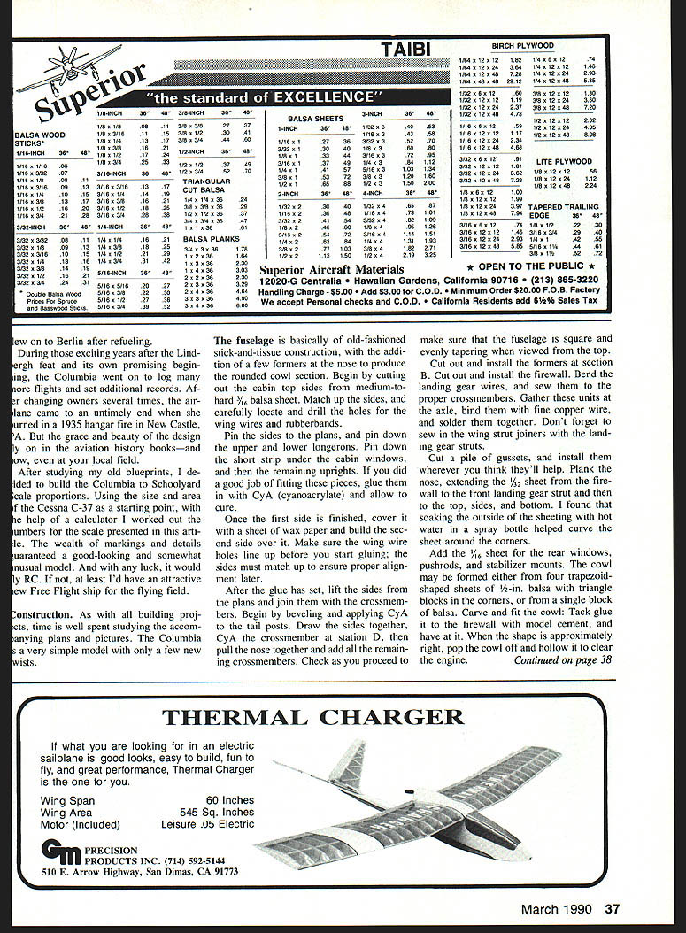
- Left: Dummy radial engine cylinders add authentic detail. Model spinner and cowling show blocks and the cooling-air intake. Note modified Z-bends at the base of the wing struts.
- Right: Small nylon landing-gear clips anchor the wing struts. A wing rubber-band strut pulls the panels together and locks; the clips are mounted on the wing. Since wing dihedral is established by the length of the struts, the builder must take care cutting and trimming struts precisely.
Most radial-engined airplanes don't offer the long nose moment this one has, but it contributes a great deal to model balance. The large, unique rudder shape designed for the Columbia adds singular charm. Chamberlin got mileage from the extensive advertising lettering on the original; a simplified cutout MonoKote trim sheet is available, and precut varieties and vinyl lettering are on the market if you don't want to cut your own. Note the quick-release wing struts that facilitate wing removal.
The model: 40-inch wingspan, about 11 ounces build weight for best performance. It retains fine Free-Flight characteristics and flies itself; modern RC gear adds about 3–4 ounces. Two-channel control; can be hand-launched or ROG. Finish scheme duplicates the original Columbia: fuselage in MonoKote dull silver, wings white with black Geotype lettering. Struts and fairings are available from local art-supply sources; covering the model takes patience and about a day to complete.
Construction
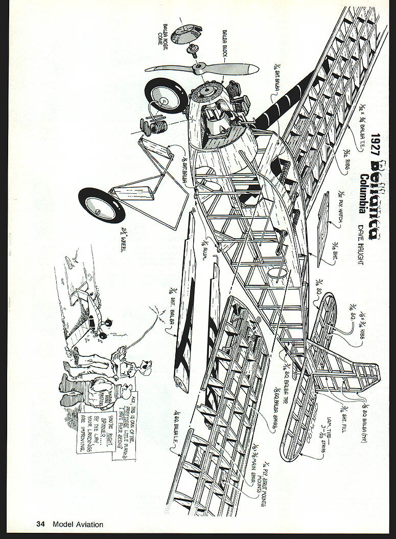
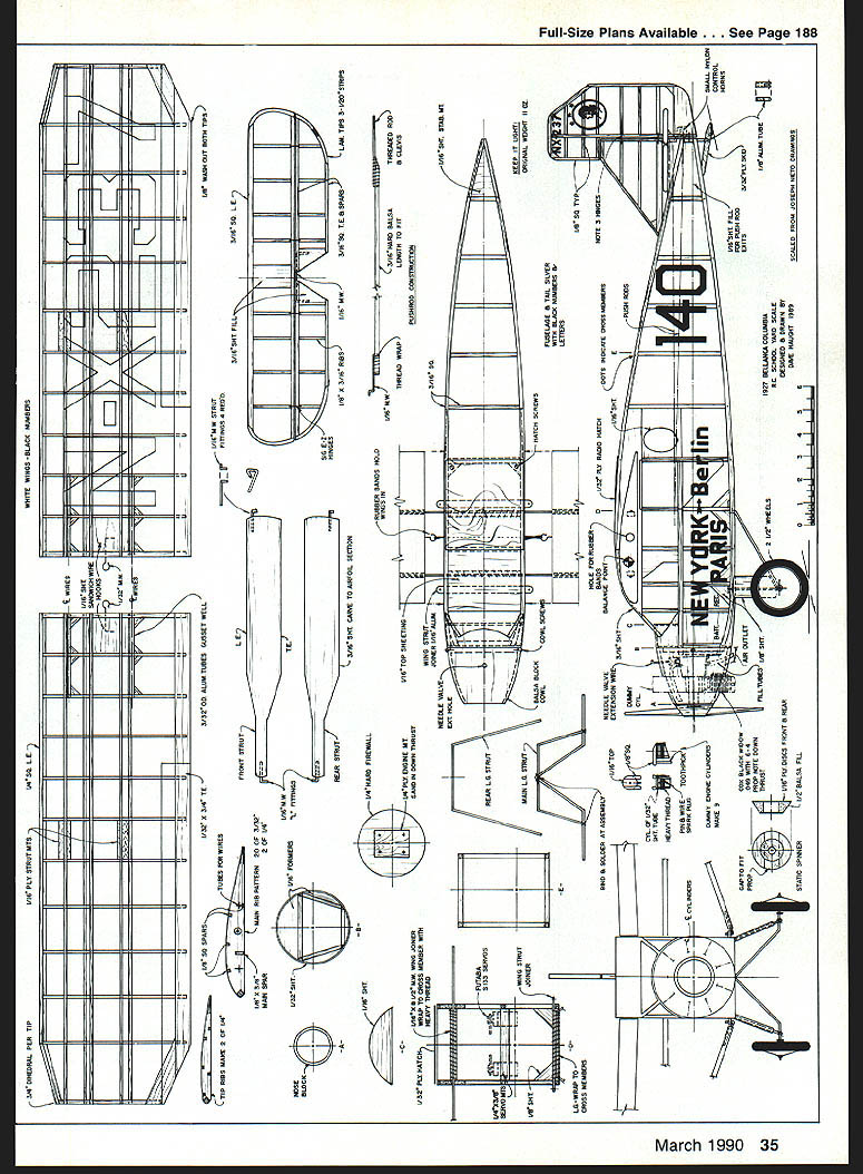
As with all building projects, time is well spent studying the accompanying plans and pictures. The Columbia is a very simple model with only a few new twists.
Fuselage
The fuselage is basically old-fashioned stick-and-tissue construction, with a few formers at the nose to produce the rounded cowl section.
- Begin by cutting the cabin top sides from medium-to-hard 3/16-in. balsa sheet. Match the sides and carefully locate and drill the holes for the wing wires and rubber bands.
- Pin the sides to the plans and pin down the upper and lower longerons. Pin down the short strip under the cabin windows and then the remaining uprights. If you did a good job fitting these pieces, glue them with CA (cyanoacrylate) and allow to set.
- Once the first side is finished, cover it with a sheet of wax paper and build the second side over it. Make sure the wing wire holes line up before gluing; the sides must match to ensure proper alignment later.
- After the glue has set, lift the sides from the plans and join them with the crossmembers. Bevel and apply CA to the tail posts. Draw the sides together, fold the CA crossmember at station D, then pull the nose together and add the remaining crossmembers. Check frequently to ensure the fuselage is square and evenly tapering when viewed from the top.
- Cut out and install the formers at section B and the firewall.
- Bend the landing-gear wires and sew them to the proper crossmembers. Gather these units at the axle, bind them with fine copper wire, and solder them together. Sew in the wing strut joiners with the landing gear struts.
- Cut a pile of gussets and install them wherever helpful.
- Plank the nose by extending 3/32-in. sheet from the firewall to the front landing gear strut and then to the top, sides, and bottom. Soaking the outside of the sheeting with hot water in a spray bottle helps curve the sheet around the corners.
- Add 1/16-in. sheet for the rear windows, pushrod openings, and stabilizer mounts.
- The cowl may be formed from four trapezoid-shaped sheets of 1/8-in. balsa with triangle blocks in the corners, or from a single block of balsa. Carve and fit the cowl; tack-glue it to the firewall with model cement and let it set. When the shape is roughly right, remove the cowl and hollow it to clear the engine.
Mount the engine, then cut openings in the cowl so it can be slipped on in one piece over the engine. Drill two holes for the cowl-retaining screws, soak the holes with CA, and install the cowl when the glue is dry. Finish-sand the fuselage.
Install the landing-gear fairings and sand to shape. Install and sand the hatch cover. The hatch can be hinged to the top of the fuselage with the MonoKote covering; two small sheet-metal screws keep it closed at the rear.
Tail surfaces
Begin by forming the stabilizer tips.
- Cut three strips 7/8 x 1/4 x 6 in. long and soak them in hot water for a few minutes.
- Wax the form edges with a white crayon. Run the strips between your fingers as you take them out of the water to remove some excess water and give them a little pre-bend.
- Apply a light coat of white glue to one side of each strip before stacking the next. Continue until all three strips are stacked and wet.
- Holding one end of the strips against the trailing edge of the form, pull the strips around the form with enough tension to force out excess water and glue but not so much as to break them. Secure with pins and tape until dry.
- The formed tip will be about 1/8 in. thick; sand both faces smooth and carefully slice it into two 1/16-in.-wide tips. Sand each tip to final dimension (about 3/16 in. where specified) and pin them to the plans.
Cut out the 3/16-in. sheet parts and pin the stabilizer parts to the plan. CA all joints and allow them to cure. Repeat the same procedure with the rudder and fin, using 1/8-in. balsa. Use hard balsa for sheet parts where the control horns attach, or strengthen the attachment area with a light coat of CA. Sand edges well and prepare surfaces for covering. Join the elevators with the wire connector and set the assembly aside for covering.
Wing
- Select medium-firm, straight-grained balsa strips for spars and leading edges. The trailing-edge strip will need to be trimmed to 3/16 in. for the top and bottom of the wing.
- Since all ribs except the tip ribs are the same shape (but may be different thicknesses), cut them on a band saw ensuring uniformity. Set four of the 3/32-in. ribs and the two 1/8-in. ones together, lining them up carefully, and drill the holes for the wing tubes all at once.
- Pin the main bottom spar, the rear spar, and the bottom trailing edge to the plans. Accurately position all upper ribs over the spars and glue each joint. Add the leading and trailing edges and the top spars.
- Lift the wing from the plan and install the wing tubes and gussets.
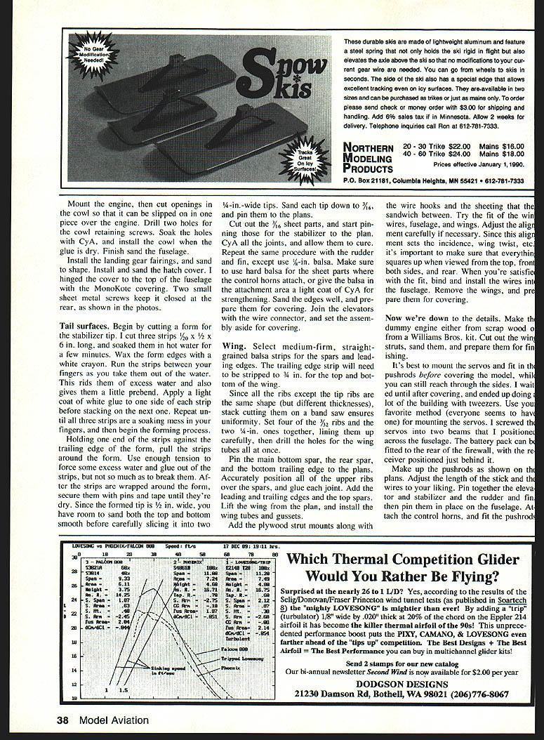
- Add the plywood strut mounts along with the wire hooks and the sheeting that the wires sandwich between. Try the fit of the wing with the wires, fuselage, and wing fairings. Adjust alignment carefully; this alignment sets incidence, wing twist, etc. Make sure everything squares up when viewed from the top, front, both sides, and rear.
- When satisfied with the fit, bind and install the wires into the fuselage. Remove the wings and prepare them for covering.
Details and finishing
- Make the dummy engine from scrap wood or a Williams Bros. kit. Cut out the cooling fins, sand, and prepare for finishing.
- It's best to mount the servos and fit the pushrods before covering; you can still reach through the sides during covering. Install the battery and receiver so they are easily accessed for adjustments.
- Make up the pushrods as shown on the plans and adjust their lengths and the wires to your liking.
- Pin the elevator and stabilizer and the rudder and fin in place on the fuselage, attach the control horns, and fit the pushrods.
- Cover the airframe, apply trim and lettering, install the dummy engine and cowl, and do final balance and control checks before flying.
Build light—about 11 ounces—for best performance. The Columbia is basically a Free-Flight design that flies itself; with modern RC it sacrifices very little and becomes an enjoyable, attractive RC schoolyard-scale model.
Transcribed from original scans by AI. Minor OCR errors may remain.

