
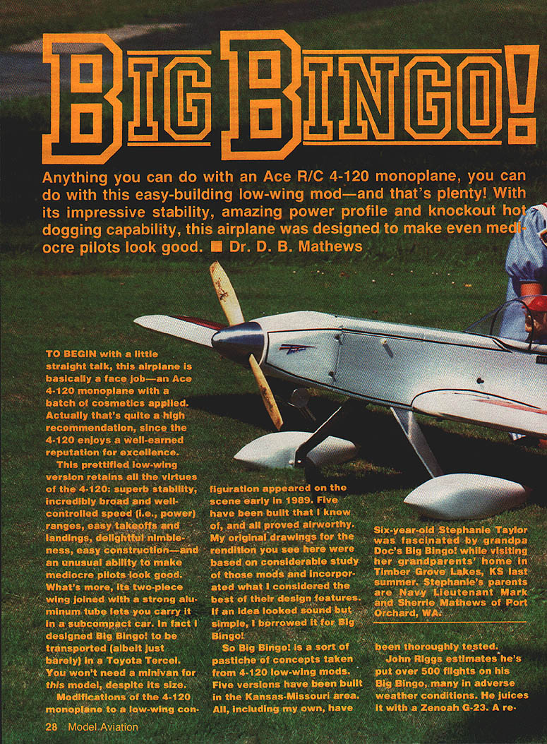
BIG BINGO!
Anything you can do with an Ace R/C 4-120 monoplane, you can do with this easy-building low-wing mod—and that's plenty! With its impressive stability, amazing power profile and knockout hot-dogging capability, this airplane was designed to make even mediocre pilots look good. — Dr. D. B. Mathews
To begin with a little straight talk: Big Bingo! is basically a face job—an Ace R/C 4-120 monoplane with a batch of cosmetics and a low-wing conversion applied. That's a high recommendation, since the 4-120 already enjoys a well-earned reputation for excellence.
This prettified low-wing version retains all the virtues of the 4-120: superb stability, broad and well-controlled speed (power) ranges, easy takeoffs and landings, delightful nimbleness, straightforward construction—and an unusual ability to make mediocre pilots look good. Its two-piece wing joined with a strong aluminum tube lets you carry it in a subcompact car; I designed Big Bingo! to be transported (albeit just barely) in a Toyota Tercel. You won't need a minivan for this model, despite its size.
Modifications of the 4-120 to a low-wing configuration appeared early in 1989. Five have been built that I know of, and all proved airworthy. My drawings for the rendition you see here were based on study of those mods and incorporate what I considered the best of their design features. If an idea looked sound and simple, I borrowed it for Big Bingo!
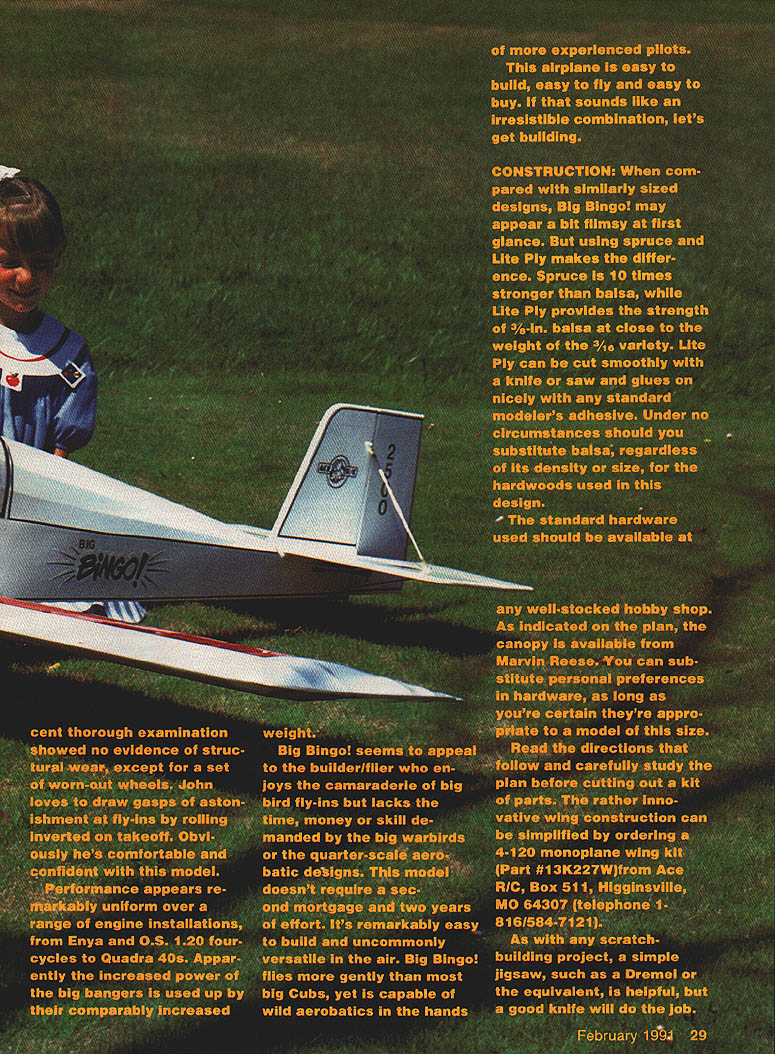
Five versions have been built in the Kansas–Missouri area; all, including my own, have been thoroughly tested. John Riggs estimates he's put over 500 flights on his Big Bingo, many in adverse weather conditions. He juices his with a Zenoah G-23 and routinely draws gasps of astonishment by rolling inverted on takeoff—clearly comfortable and confident with the model.
Performance is remarkably uniform across a range of engine installations, from Enya and O.S. 1.20 four-cycles to larger two-stroke engines such as the Sidewinder ST 2500 and Quadra 40s. The increased power of the big burners is often offset by their increased weight.
Big Bingo! appeals to builders who enjoy the camaraderie of big-bird fly-ins but lack the time, money or skill demanded by big warbirds or quarter-scale aerobatic designs. It doesn't require a second mortgage or two years of effort. It's easy to build, easy to fly and uncommonly versatile in the air—from docile flying to wild aerobatics in experienced hands.
Full-size plans: page 188.
CONSTRUCTION
Spruce and Lite Ply are the structural core of Big Bingo!. Spruce is far stronger than balsa, and Lite Ply provides the strength of 3/16-in. balsa at close to the weight of 3/32-in. Lite Ply cuts smoothly with a knife or saw and glues well with standard model adhesives. Under no circumstances should you substitute balsa, regardless of density or size, for the hardwoods specified.
Standard hardware should be available at any well-stocked hobby shop. The canopy shown on the plan is available from Marvin Reese. You may substitute personal preferences in hardware, but be certain they are appropriate for a model of this size.
Tools: As with any scratch-building project, a simple jigsaw (e.g., a Dremel) is helpful, though a good knife will do for many tasks. Medium-viscosity CyA (cyanoacrylate) and epoxy adhesives were used in the prototypes.
- Read the directions and study the plan before cutting.
- The innovative wing construction can be simplified by ordering an Ace R/C 4-120 monoplane wing kit (Part #13K227W) from Ace R/C, Higginsville, MO.
Materials and general tips
- Use a smooth, flat work surface to keep the structure straight—straight models fly straight.
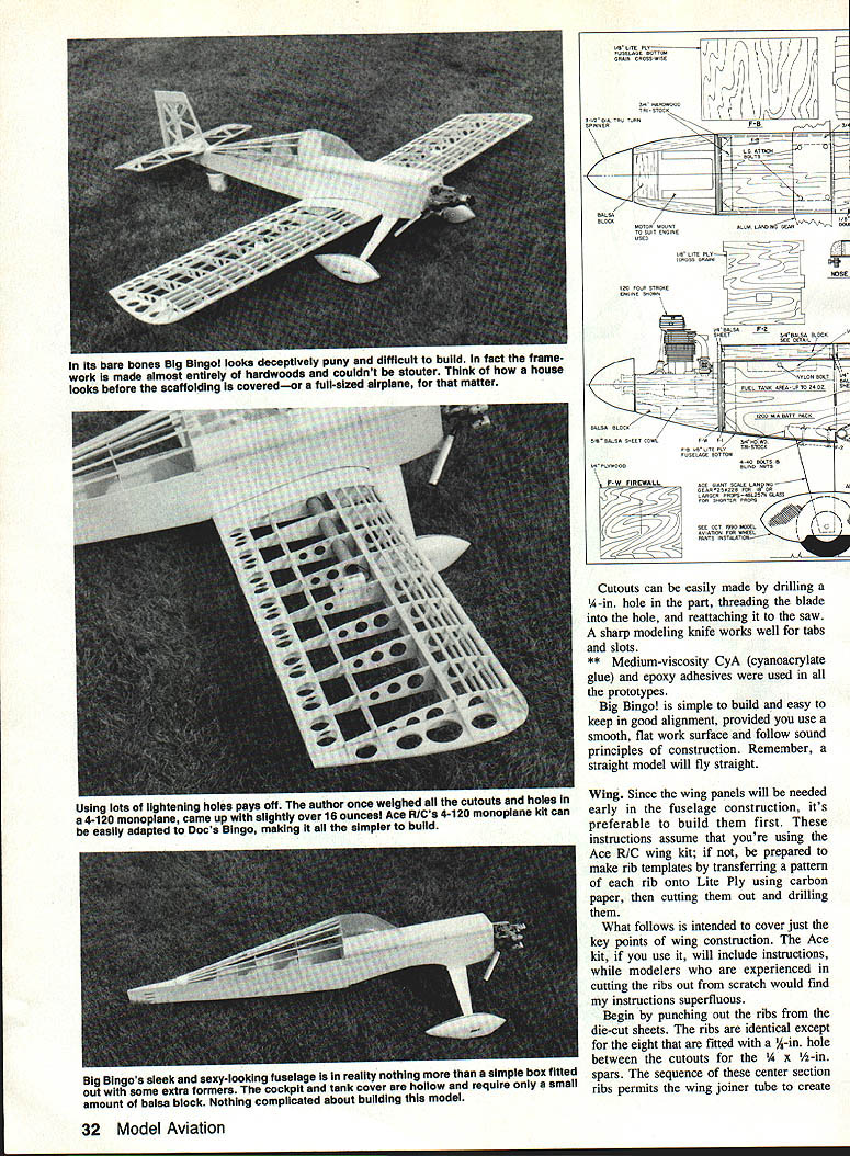
- Cutouts and lightening holes are effective: in one 4-120 the author weighed all the cutouts and came up slightly over 16 ounces.
- Cutouts can be made by drilling a 1/4-in. hole, threading the blade into the hole, and reattaching it to the saw. A sharp modeling knife works well for tabs and slots.
Fuselage
- Transfer fuselage parts with carbon paper from the plans; use a straightedge for straight lines.
- The joint line shown on the plan assumes 36-in. Lite Ply sheets; if you use 48-in. sheeting the joint isn't necessary.
- Install doublers with epoxy and align the structure using small Lite Ply scraps in the matching slots; weight down while the epoxy cures.
- Fit F-1, F-2, F-3 and the cockpit floor without gluing; trim tabs and slots if needed and be sure the assembly is square in all planes. Tape the unit together and flow medium CyA along the joints for a double-glue bond.
- The tank hatch floor is held in place with masking tape rather than glued to the sides to provide access.
- Glue in the hardwood landing gear block and reinforce with a piece of hardwood triangular stock.
- Install the rear bottom piece by drawing the sides in with masking tape; with the 3/4 x 1/4-in. tail post in place, clamp the fuselage rear and square. Apply CyA along joints.
- Glue the slotted tail wheel block in place with the slot centered under the fuselage bottom.
- Glue T-3 atop F-3 using scrap Lite Ply reinforcements. Add turtledeck formers and epoxy the triangular stabilizer floor flush with the tops of the sides.
- Install 1/4 x 1/4-in. spruce stringers. Note that some former halves are notched or flat to permit stringer adjustment for a smooth contour. Trim and sand the stringers to round them off.
Cockpit and hatch
- Build balsa rails on the fuselage, cut a Lite Ply top, and glue it to the rails. Use balsa block to form quarter-round tapers into the fuselage sides.
- After final sanding, cut the hatch area free with a razor saw. Attach two strips of 1/4-in. plywood to the hatch bottom and thread 4-40 bolts through the fuselage sides into them to retain the hatch.
Wing hold-downs
- Position hardwood wing hold-down blocks as shown on the plan: centered 3 in. from the rear of F-2, with the rearmost one 3 in. from the front of F-3. They must be flush with the wing saddle and may be rasped to final shape.
- Place the completed wing in the saddle, mark equidistance from the tail post, drill through the wing into the fuselage, remove the wing, tap the blocks for 1/4-20 bolts, and enlarge the wing holes to 1/4 in.
Tank and battery
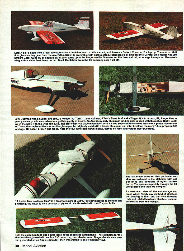
- Although enough room is provided for a 20-oz. tank, a 16-oz. tank is sufficient for most engines including large SuperTigres. Coat the inside of the compartment and the bottom of the hatch with epoxy before installing the tank.
- Position the tank as high as possible with both lines exiting the firewall and cradle it in foam rubber. A 1,000-mAh flat battery pack will fit under a 16-oz tank.
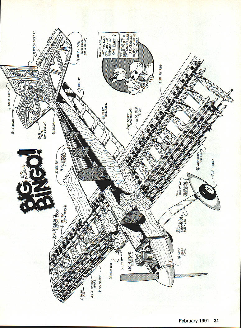
Engine and cowl
- Drill the firewall to suit your chosen engine and mount. Examples used in prototypes include SuperTigre 2500, Sidewinder ST 2500, ST 3000, Zenoah G-23, and others.
- A carved wooden cowl is shown; fuelproof the cowl interior. Use a spinner backplate drilled for your engine—3-1/2 in. has worked well for ST 2500/3000 setups.
- Engine mounting options include sidewinder mounts, engines upright in the nacelle, or commercial fiberglass mounts.
Tail surfaces and controls
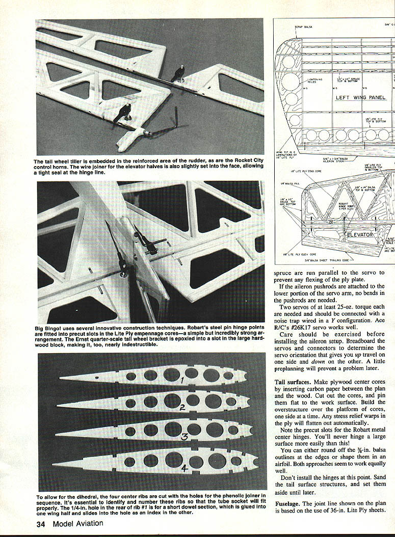
- Make plywood center cores for tail surfaces by transferring plans with carbon paper. Pin flat and build the overstructure over the platform of cores, one side at a time.
- Note the precut slots for Robart metal center hinges—these make hinging large surfaces straightforward.
- You may round the 3/16-in. balsa outlines or shape them with an airfoil; both work.
- Do not install hinges at this point; sand surfaces and set aside.
- Tack-glue the stabilizer to the fin, keeping it perpendicular and aligned with the rear of the stab. File a notch in the stab trailing edge for elevator joiner wire clearance.
- Slip the tailwheel tiller arm into the rudder and place the assembly on the stabilizer mount. Slide the tongue of the tailwheel bracket into the slot in the tailwheel block and attach with epoxy. Tack-glue the stabilizer to the fuselage.
Pushrods and linkage
- Use fiberglass pushrods and appropriate hardware. Cut 4-40 threaded rods to 2-3/8 in. for the front links and 6-1/2 in. for the rear.
- Slip Dave Brown plastic plugs over the rods, drill a 1/4-in. hole one inch from each end of the shaft, poke the bent wire through, smear the plug with epoxy or thick CyA, and push into the shaft. Secure the wire with thin CyA.
- I prefer a 4-40 solder link on the servo end and an adjustable clevis on the surface end.
- Slip pushrod guides over each pushrod and install them in the fuselage. The rudder and elevator pushrods cross over: the rudder pushrod exits the lower fuselage slot and the elevator pushrod exits the top slot.
- Install Rocket City 1/4-scale horns in the predrilled holes.
- Adjust wire length on the servo end for neutral positions, then disconnect at the horn end, pull rods forward, and solder the front links with silver solder.
Landing gear
- Choice of landing gear is shown on the plan. For 1.20-strokers or smaller two-strokes, the Klett fiberglass gear included in the Ace 4-120 kit is preferable since it is nearly a pound lighter than the longer aluminum unit. The Klett unit safely clears only up to 16-in. props.
- The landing gear can be secured to the fuselage block with a #6 x 1-in. sheet metal screw or with 6-32 bolts and blind nuts.
Notes on specific construction details
- The lightening holes shown in some turtledeck formers are appropriate for lighter powerplants that tend to make the plane tail-heavy. Larger engines (ST 2500 and up) can cause a nose-heavy condition; add the recommended reinforcements in that case (3/4 x 1/4-in. strips inside the fuselage top from F-3 rearward, along the bottom/side joint, and a 3/4-in. triangular balsa reinforcement at the fin-stab junction if needed).
- Arrange right and left sheeting pieces so the better side faces outward. The Big Bingo design locks together and overcomes most warpage.
- A buried tank is a potential leak source. Provide access to the tank and plumbing: the hatch is held by plywood rails threaded with 1/4-20 nylon bolts in the prototype.
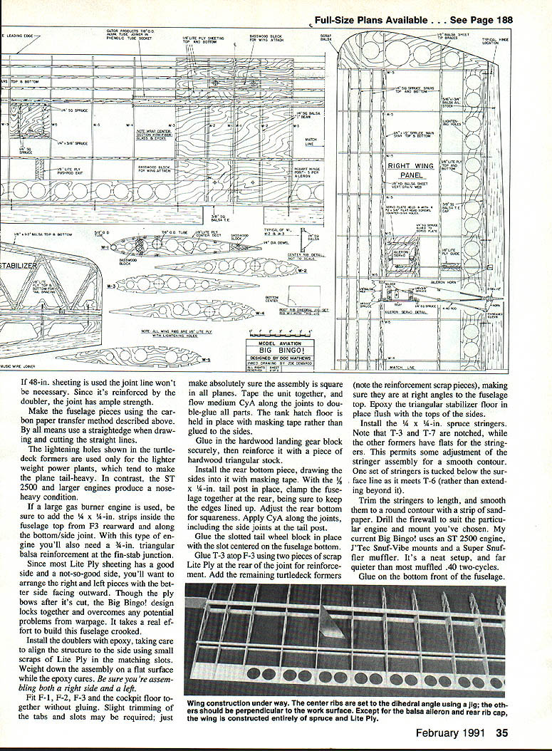
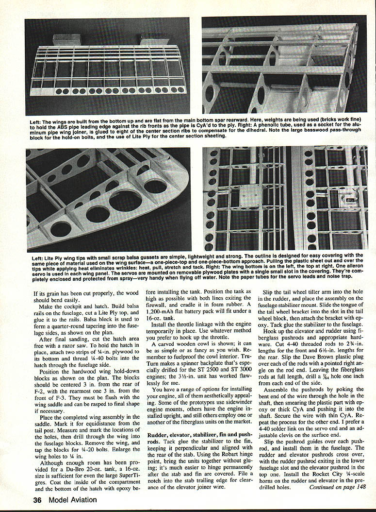
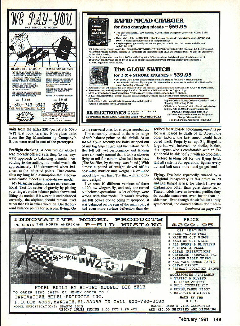
Wing (build early)
Since wing panels are needed early in fuselage construction, build the wing first. These instructions assume you are using the Ace R/C wing kit; if not, make rib templates by transferring each rib pattern onto Lite Ply using carbon paper, then cut and drill.
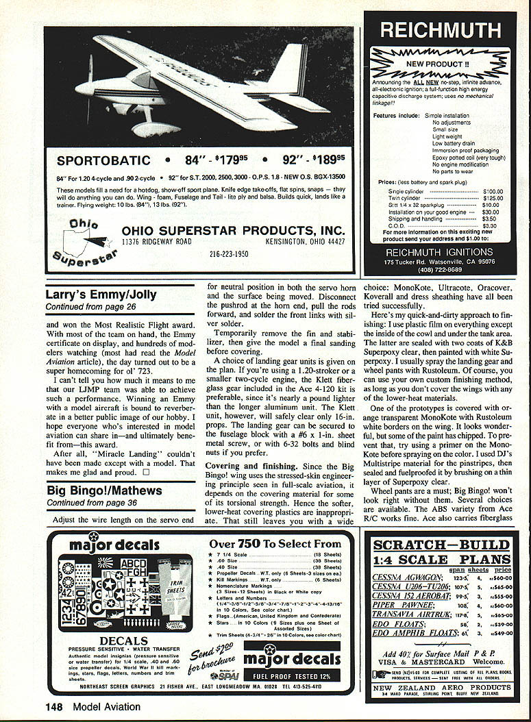
- Begin by punching out the ribs from the die-cut sheets. Ribs are identical except for a number fitted with holes for the spars and the wing joiner tube; label them carefully.
- The sequence of center-section ribs permits the wing joiner tube to set the dihedral angle. Note orientation differences among ribs (e.g., tube hole positions) and label them to avoid assembly errors.
- Prep the PVC leading-edge pipe with 120-grit sandpaper for good adhesion. Some bowing is normal; the pipe will straighten as it's glued to the ribs.
- Add hardwood bolt blocks and sheet the top center section; then add top spars, wing tips, etc.
Hot Stuff / Sprayment assembly technique (fast and repeatable)
- Lightly spray a flat piece of plate glass with 3M Sprayment 77. Place the plans on the glass, spray lightly, and cover them with waxed paper (not plastic wrap).
- Coat the waxed paper heavily with Sprayment and allow it to become tacky.
- Position parts on the plans and hold them with Sprayment. Start with the bottom trailing edge sheet, then add bottom spars, using a rib or two for precise alignment. The airfoil is flat from the bottom spar rearward, which simplifies alignment.
- Use a scrap ply dihedral gauge to position rib #1. Shear webs, precut and sized, position other ribs.
- Once the center-section bottom sheeting is in place, flow CyA on both sides of rib joints to glue.
- Add the PVC leading edge and glue in place. Sheet the top center section and install the remaining components.
Reinforcements and servo installation
- Add 1/8 x 1/4-in. balsa strips, block sanded to contour, to center-section ribs where they meet Lite Ply sheeting to increase gluing area.
- Mount the aileron servo plate to the wing with 3-48 bolts and blind nuts rather than screws. Run two strips of scrap spruce parallel to the servo to prevent flexing of the ply plate.
- If the aileron pushrods attach to the lower portion of the servo arm, no bends in the pushrods are needed.
- Two servos of at least 25-oz. torque each are recommended and should be connected with a noise trap wired in a Y configuration (Ace R/C #26K17 works well).
- Breadboard the servos and connectors to determine orientation that gives up travel on one side and down on the other; preplanning prevents later problems.
Tail surfaces
- Use the Robart metal center hinges in the precut slots for easy hinging of large surfaces.
- Sand tail surfaces and delay final hinging until after covering for easier alignment.
Covering and finishing
Because the Big Bingo! wing uses a stressed-skin approach, the covering material contributes to torsional strength. Avoid softer, lower-heat covering films.
- Suitable coverings: MonoKote, Ultracote, Oracover, Koverall, dress sheathing.
- My approach: use plastic film on everything except the inside of the cowl and under the tank area. Seal those areas with two coats of K&B Superpoxy clear, then paint with white Superpoxy.
- Spray landing gear and wheel pants with Rustoleum if desired.
- For transparent film finishes (e.g., orange transparent MonoKote), consider priming the MonoKote before spraying paint to prevent chipping. DJ Multistripe or ABS striping materials work well for accenting.
- Fiberglass wheelpants and gear from various manufacturers have been used successfully in prototypes.
Preflight checking
- Balance: Place your fingers on the balance points shown on the plans and lift the model. If built and balanced correctly, the airplane should remain level rather than tilt. Use forward balance points for easy "pussycat" flying and rearward points for stronger aerobatics.
- Test all systems, tighten every nut and bolt, and verify control throws and linkages before flight.
Flying
- These 4-120-derived models have an odd but delightful idiosyncrasy: they perform outside maneuvers even better than inside ones. Even though the airfoil isn't truly symmetrical, Big Bingo! handles inverted flight exceptionally well.
- In skilled hands the model can perform snaps, spins, figure eights, vertical eights, Cuban eights, snaps at the top of an inside loop, inverted flat spins, and more. It is limited mainly by the pilot's skill.
- Big Bingo! is aerodynamically clean and slows well without becoming squirrelly. It tracks exceptionally well on takeoff, typically needing only a touch of right rudder halfway down the run. It can be trimmed to fly hands-off and will go exactly where it's pointed when maneuvering.
- A fun routine: during vertical climbout, alternately deflect the rudder left and right to make the plane "wiggle," then stall turn and half roll on the descent—a maneuver I call the "Bingo wiggle."
- Landing: because the landing gear is farther forward than normal, you can do wheel landings by slowing well out on final and bringing it in without a flare.
Field notes and anecdotes
- I've seen ten different 4-120 low-wing versions fly; only one performed poorly, and its problems were due to misproping, incorrect balance, excessive surface deflection, and an inexperienced pilot.
- In one incident the bolts stripped out of a large SuperTigre and the muffler fell off; with nearly a pound of weight removed from the nose the model still flew nearly normally.
- Practical details from prototypes: four wing hold-down blocks, servos on rails, carbon-fiber pushrods, tall brace wires, and 4-40 threaded rods for empennage bracing (these cannot be omitted). One prototype fastened the stabilizer with solder links; sections of nylon control horns passed completely through the tailwheel block. A buried tank leaked in one example—access to plumbing is recommended.
Final note
For a large return on a modest investment, Big Bingo! is hard to beat. It offers an incredible power profile and a broad performance envelope that takes you from docile cruising to full-stop aerobatics. It's easy to build, easy to fly, and a lot of fun to own.
Full-size plans: page 188.
Transcribed from original scans by AI. Minor OCR errors may remain.

