
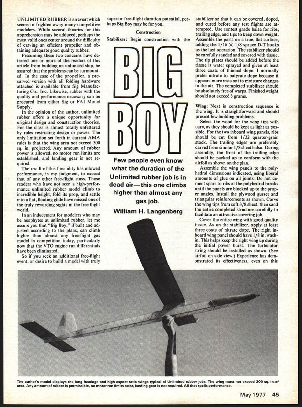
Big Boy
Few people even know what the duration of the Unlimited rubber job is in dead air—this one climbs higher than almost any gas job.
William H. Langenberg
UNLIMITED RUBBER is an event which seems to frighten away many competitive modelers. While several theories for this apprehension may be adduced, perhaps the most valid ones center around the difficulty of carving an efficient propeller and obtaining adequate good quality rubber.
Presuming these two concerns have deterred one or more of the readers of this article from building an unlimited ship, be assured that the problems can be surmounted. In the case of the propeller, a pre-carved version with all folding hardware attached is available from Sig Manufacturing Co., Inc. Likewise, rubber with the quality and performance necessary can be procured from either Sig or FAI Model Supply.
In the opinion of the author, unlimited rubber offers a unique opportunity for original design and construction theories. For the class is almost totally unfettered by rules restricting design or power. The only limitation set forth in current AMA rules is that the wing area not exceed 300 sq. in. projected. Any amount of rubber power is allowed, no motor run limits are established, and landing gear is not required.
The result of this flexibility has allowed performance, in my judgment, to exceed that of any other free-flight class. Those readers who have not seen a high-performance unlimited rubber model climb to incredible height, fold its prop, and settle into a flat, floating glide have missed one of the truly rewarding sights in the free flight world.
In an inducement for modelers who may be neophytes at unlimited rubber, let me assure you that "Big Boy," if built and adjusted according to the plans, can climb higher than almost any free-flight gas model in competition today, particularly now that the VTO engine run differentials have been eliminated.
So if you seek an additional free-flight event, or desire to build a model with truly superior free-flight durational potential, perhaps Big Boy may be for you.
Construction
Stabilizer: Begin construction with the stabilizer so that it can be covered, doped, and cured before any test flights are attempted. Use contest grade balsa for ribs, trailing edge, and tips to keep down weight. Assemble the parts on a true, flat surface, adding the 1/16 x 1/8 spruce D-T hooks as the last operation. The stabilizer should be carefully sanded and covered with tissue. The tip plates should be added before the tissue is water sprayed and given at least three coats of thinned dope. I normally prefer nitrate to butyrate dope because it appears more resistant to moisture changes in the air. The completed stabilizer should be absolutely free of warps. Finished weight should not exceed 8 grams.
Wing: Next in construction sequence is the wing. It is straightforward and should present few building problems.
Select the wood for the wing tips with care, as they should be kept as light as possible. For the two inboard wing panels, ribs should be cut from 1/32 quarter-grain stock. The trailing edges are preferably carved from similar 1/8 sheet balsa. During assembly, the front of the trailing edge should be packed up to conform with the airfoil as shown on the plan.
Assemble the wing panels to the polyhedral dimensions indicated, using liberal amounts of glue on all joints. Do not cement spars to ribs at the polyhedral breaks until the panels are blocked up to the proper angles. Install the plywood gusset and triangular reinforcements as shown. Carve the wing tips from soft 3/8 sheet, then sand the entire completed structure carefully to facilitate an attractive covering job.
Cover the entire wing with good quality tissue. As on the stabilizer, apply at least three coats of nitrate dope. The right inboard wing panel should have 1/8 in. wash-in. This helps keep the right wing up during the initial power burst. The turbulator string should be installed as shown. (See airfoil on side view.) Experience has demonstrated its effectiveness, even on this multi-spar wing. Set the wing aside and allow it to cure thoroughly. Finished weight should not exceed 32 grams.
Fin:
The fin is cut from soft 3/32 in. sheet to the outline shown on the plans. It should be carved and sanded to a streamline shape as indicated so as to give a left turn in the glide.
Fuselage:
Select four hard 1/8 x 1/8 balsa strips, 48 in. long, for the longerons. If 48-in. length stock is not available, 36 in. strips can be used if they are properly spliced. When splicing, use a 3/4-in. long bevel, carefully fitted, and double glue the joints. Do not locate the splices at the same distance along the fuselage length. The best position for a splice is at the junction of two diagonals, which act as reinforcing members.
Build two fuselage sides on the plan, ensuring that the diagonals do not run the same directions on both sides. Add the 1/8 sheet fillers for the rear rubber peg. It is prudent to dope both flat sides of the 1/16 x 1/8 diagonals before cutting them to size so that the rubber lube will not be absorbed by the raw wood. The longerons should also be doped before building the fuselage sides.
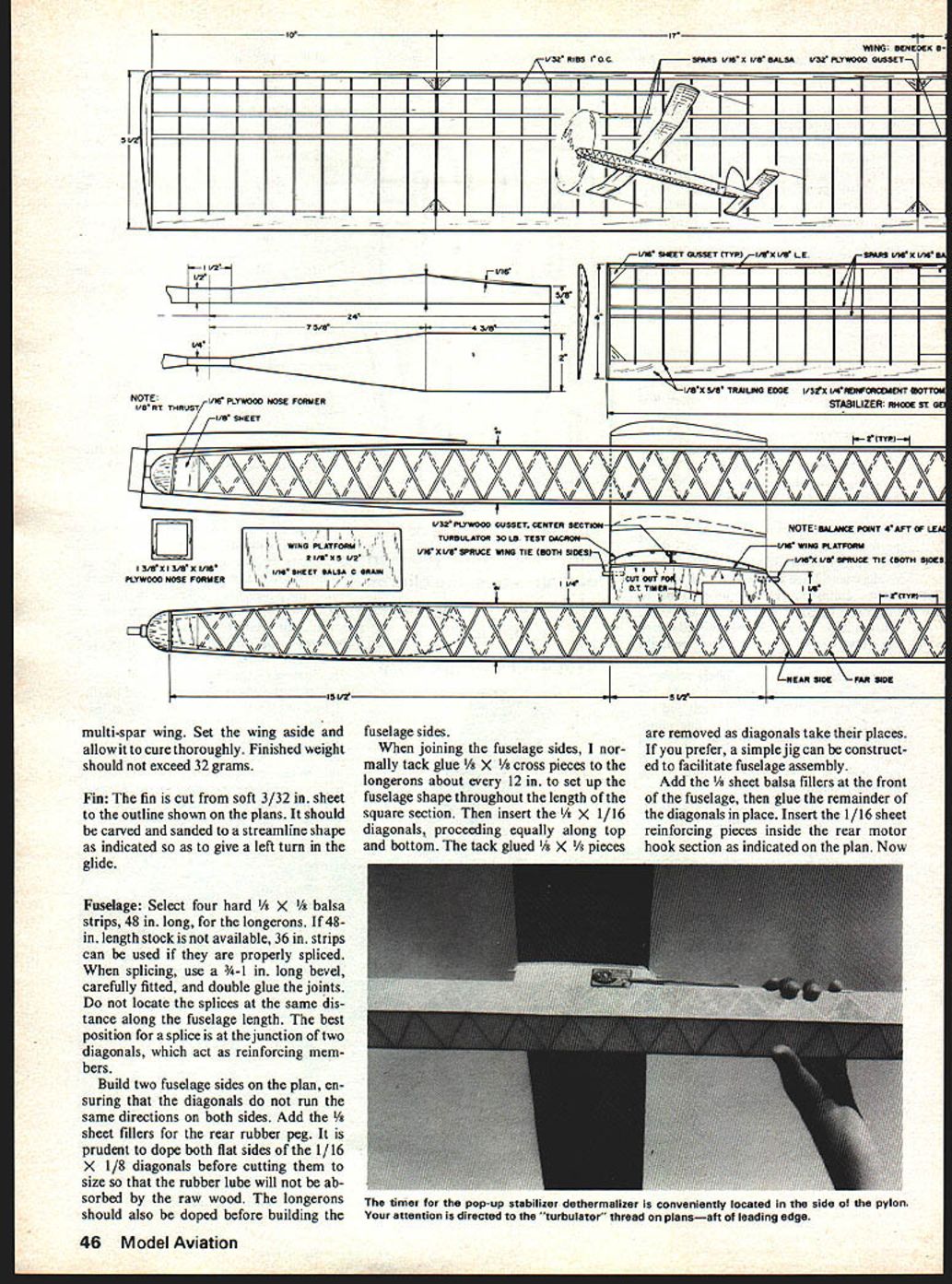
When joining the fuselage sides, I normally tack glue 1/8 x 1/8 cross pieces to the longerons about every 12 in. to set up the fuselage shape throughout the length of the square section. Then insert the 1/4 x 1/16 diagonals, proceeding equally along top and bottom. The tack glued 1/8 x 1/8 pieces are removed as diagonals take their places. If you prefer, a simple jig can be constructed to facilitate fuselage assembly.
Add the 1/8 sheet balsa fillers at the front of the fuselage, then glue the remainder of the diagonals in place. Insert the 1/16 sheet reinforcing pieces inside the rear motor hook section as indicated on the plan. Now carve and sand the 1/8 in. right thrust into the fuselage nose. Cut out the 1/16 plywood nose former and glue it accurately in place. Sand the entire fuselage smooth and cover it with tissue, grain perpendicular to the longerons. For durability you may wish to double cover the fuselage bottom, cross graining the tissue.
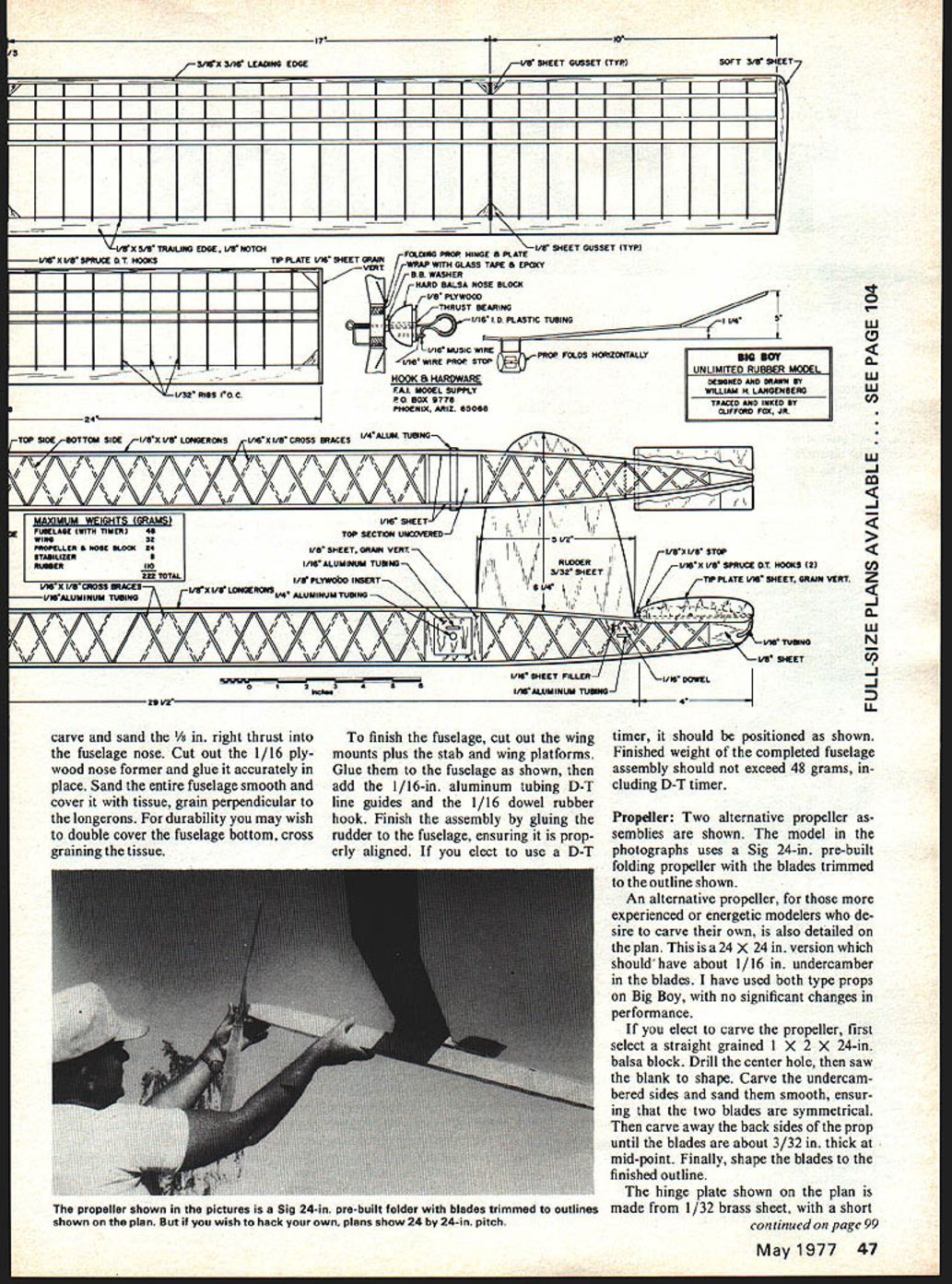
To finish the fuselage, cut out the wing mounts plus the stab and wing platforms. Glue them to the fuselage as shown, then add the 1/16-in. aluminum tubing D-T line guides and the 1/16 dowel rubber hook. Finish the assembly by gluing the rudder to the fuselage, ensuring it is properly aligned. If you elect to use a D-T timer, it should be positioned as shown. Finished weight of the completed fuselage assembly should not exceed 48 grams, including D-T timer.
Propeller:
Two alternative propeller assemblies are shown. The model in the photographs uses a Sig 24-in. pre-built folding propeller with the blades trimmed to the outline shown.
An alternative propeller, for those more experienced or energetic modelers who desire to carve their own, is also detailed on the plan. This is a 24 x 24 in. version which should have about 1/16 in. undercamber in the blades. I have used both type props on Big Boy, with no significant changes in performance.
If you elect to carve the propeller, first select a straight grained 1 x 2 x 24-in. balsa block. Drill the center hole, then saw the blank to shape. Carve the undercambered sides and sand them smooth, ensuring that the two blades are symmetrical. Then carve away the backs of the prop until the blades are about 3/32 in. thick at mid-point. Finally, shape the blades to the finished outline.
The hinge plate shown on the plan is made from 1/32 brass sheet, with a short length of 1/32-in. I.D. brass tubing rolled and epoxied into each end. The 1/32 hinge wire connects the blades to the hub.
Complete the propeller assembly by carving the noseblock from hard balsa. The ball bearings, shaft, thrust bearing, and spring shown in the drawing can be obtained from FAI Model Supply, Box 9778, Phoenix, AZ 85068. A 1/8 plywood insert glued to the rear of the noseblock should fit snugly into the front of the fuselage.
Construction
Stabilizer
Begin construction on the stabilizer. Few people know what duration unlimited-rubber jobs do in dead air—this climbs higher than almost any gas job. The stabilizer can be covered, doped and cured before the test flights are attempted. Use contest-grade balsa ribs; keep trailing-edge tips as light as possible. Assemble parts on a true, flat surface, adding 1/16 x 1/8 spruce D-T hooks. As a last operation the stabilizer should be carefully sanded and covered with tissue. Tip plates should be added before covering; water-spray the tissue and give at least three coats of thinned dope. I normally prefer nitrate or butyrate dope because it appears resistant to moisture changes in the air. The completed stabilizer should be absolutely free of warps. Finished weight should not exceed 8 grams.
Wing
Next in the construction sequence is the wing. It is straightforward and should present few building problems. Select wood for the wing tips; care should be taken to keep them as light as possible. The two inboard wing-panel ribs should be cut from 1/32" quarter-grain stock; trailing edges are preferably carved similar to 1/8" sheet balsa. During assembly, pack up the front and trailing edges to conform to the airfoil shown on the plan. Assemble the wing panels, using the polyhedral dimensions indicated and liberal amounts of glue at joints, cementing spars and ribs at the polyhedral breaks until panels are blocked up at proper angles. Install the plywood triangular gusset reinforcements shown. Carve the wing tips from soft 3/8" sheet and sand the entire completed structure carefully to facilitate an attractive covering job. Cover the entire wing with good-quality tissue. As with the stabilizer, apply at least three coats of nitrate dope. The right-hand wing panel should have 1/8" wash-in to help keep the right wing up during the initial power burst. A turbulator string should be installed as shown; see the airfoil side view—experience has demonstrated its effectiveness.
Set the wing aside and allow it to cure thoroughly. Finished weight should not exceed 32 g. The propeller and nose block should be given at least three coats of dope before assembling. Ensure that the propeller blades are properly balanced and track properly. Finished weight of the propeller assembly should not exceed 24 grams.
Flight Preparation: Make up at least two 1/4 in. rubber motors of 16 strands. After washing, drying and lubing the motors, break them in initially using the stationary stretch method. To do this, I hammer two large nails securely into a fence about six motor lengths apart. A motor is then stretched over the nails and left there for five minutes. The stretched motors should be about 42 in. long.
Now assemble the completed model and insert a rubber motor. Check that the alignment, wing wash-in and incidence, and thrust are correct. Also verify the CG location with prop blades folded. Shift the position of the D-T timer if necessary to ensure the CG is located precisely as shown on the plan. Ready-to-fly weight should be equal to or less than the 222-gram total itemized on the plan.
For the modeler interested in serious unlimited rubber competition, I believe a reliable, sturdy winder and a winding stooge are musts. A winding stooge custom designed for your own car is relatively easy to build. The twin advantages of an immovable holder when winding, and freedom to test fly alone, are significant.
Flying: Under calm conditions, hand glide the model and add packing under the stabilizer leading or trailing edge until the model floats with just a slight left turn.
The ship should be very docile to adjust under power. Start with about 200 turns. The model should climb to the right, straighten out before the prop folds, and then glide to the left. Use thrust adjustments, rudder tab, and stab tilt to obtain this pattern. Proceed in increments until full turns are reached. Under full power, the model should climb in a steep right corkscrew, with the nose pointed up until just before the prop folds. Motor run should be about one minute.
One of the advantages of the unlimited rubber class is that the duration potential exceeds the flight maximum, unless down air is encountered. Unlike a Wakefield, therefore, I do not believe it is mandatory to wind the motor to absolute capacity on every flight.
I normally wind the motors on my Big Boy between 700-750 turns, depending on the feel of the rubber. Maximum capacity, by contrast, is about 800 turns. While Sig or FAI Model Supply rubber, in my opinion, is not equivalent to Pirelli for Wakefield events, it is certainly adequate in Big Boy. Because of its smooth texture, it is also less liable to nick or break. On several occasions, I have used the same motor for all three competitive flights!
If you are unable to build your Big Boy down to the structural weight shown on the plan, and the climb suffers accordingly, I suggest an increase in power from 16 to 18 strands. One of the real joys of the unlimited rubber event is to watch your model climb to a great height, which it may not do, unless thermally assisted, if underpowered.
Try unlimited rubber—you'll like it!
Transcribed from original scans by AI. Minor OCR errors may remain.

