
Bill Fuori's Quarter Midget
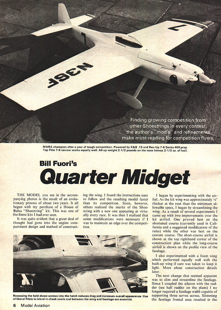
THE MODEL you see in the accompanying photos is the result of an evolutionary process of about two years. It all began with my purchase of a House of Balsa "Shoestring" kit. This was one of the finest kits I had ever seen. It was quite evident that a great deal of thought had gone into the engine compartment design and method of constructing the wing. I found the instructions easy to follow and the resulting model faster than its competition. Soon, however, others realized the merits of the Shoestring with a new one appearing at virtually every race. It was then I realized that some modifications were necessary if I was to maintain an edge over the competition.
I began experimenting with the airfoil. As the kit wing was approximately 1/8" thicker at the root than the minimum allowable specs, I began by streamlining the wing. As a result of several experiments I came up with two improvements over the kit airfoil. One proved best on the shortened course (currently used in California and a suggested modification of the rules) while the other was best on the current course. The short-course airfoil is shown at the top righthand corner of the construction plan while the long-course airfoil is shown on the profile view of the fuselage. I also experimented with a foam wing which performed equally well with the built-up wing if care was taken to keep it light. More about construction details later.
The next change that seemed apparent was to slim and streamline the fuselage. Since I coupled the aileron with the rudder (see half rudder on the plans) I no longer required a fuselage width capable of supporting three servos across. Slimming the fuselage frontal area resulted in the engine head protruding through the cheek cowl, but I prefer this to a completely cowled engine. The result of the above changes, together with some construction variations discussed later, resulted in a truly competitive racer. This can be supported by the fact that it has brought home the hardware in each of the many races held by MARA (Metropolitan Air Racing Assoc.). However, it has more assets than simply raw speed. Its greatest asset is in its ease of handling and stability. I have never found it to drop the slightest in the tightest of turns with no opposite rudder required to accomplish this.
The model may be constructed from scratch using a built-up or foam wing, or it may be constructed by modifying a House of Balsa Shoestring Kit. I would suggest the latter if time is a critical factor. In the remainder of the article I will describe the steps in scratch-building the model. The first step is to determine whether a built-up or foam type wing will be used.
Construction Fuselage—Part 1: Begin the fuselage construction by cutting out the 1/8 in. fuselage sides, the 1/32 in. plywood doubler, and the three plywood formers. It is important to select matched sheets for the sides, and to cut out the holes in the doubler to allow the sides to contour properly as well as to keep down the overall weight. If the wing is to be the foam type, the diameter of the front two lightening holes is reduced to 1 in., and the shaded area shown on the plan must be marked on the fuselage sides for later removal. The plywood doublers are then epoxied to the sides being certain to make a left and a right side. When this has thoroughly dried mark the position of formers 2 and 3, and if a built-up wing is to be used, mark and drill out the holes for the fiberglass arrowshafts. Glue 5/16 in. triangular strips at the top and bottom of each side, leaving a cutout for former 3. Install 3/16 in. triangular stock at the bottom of each side between formers 1 and 2, 1/4 x 1/2 balsa hatch supports between formers 2 and 3, and a 1/16 x 3/8 cross brace. Formers 2 and 3 are then epoxied to the sides. Be sure the formers are square with the fuselage sides. After this has set, filler and the triangular filler at the rear are epoxied in and the assembly set aside to dry thoroughly.
Next epoxy a 2 x 4 balsa block to the front of former 1 at a right-angle to the former. The right face of this block must line up with the center line of former 1. Cut out and epoxy the 1/2 in. diameter ply disk to the front of this block so that it is centered with respect to the engine thrust-line.
Bill Fuori's Quarter Midget
When this has dried, mark the location of the left cheek cowl and rough shape this block, being careful not to touch the marked cowl area. The bottom of this block must be cut so as to form a straight line with the lower edges of the fuselage sides.
The inside of this block now may be hollowed out to allow for the particular engine and mount. The 1/2 in. lower nose block is now glued to the 3/4 in. block or laminated 3/8 in. blocks are then tack-glued to the top of the fuselage from former 1 aft. Another such block is permanently glued to the top of the fuselage and to the front of former 1. Sand these blocks as close as possible to their final shape.
Now mark the position of the fuselage sides and formers on the rear top block from inside the fuselage. Cut this block with a razor saw to separate the tank compartment hatch from the top deck. Remove these blocks and hollow out as per the plans. A 1/64 in. ply edge protector is now glued to the rear of the hatch and the front of the deck. These blocks are now set aside until after the wing has been constructed.
Foam Wing: The foam-wing version follows standard constructional techniques. Cutouts should be made for the plywood dihedral braces prior to covering the wing. Each panel is then covered with 1/16 in. sheet and fitted with leading-edge, trailing-edge, and tip blocks. Be sure to groove the T.E. at the root to accept the 1/16 in. ply fillet support.
The area marked out earlier on the fuselage sides is now removed. Two pieces are then removed from the wing center section to allow the wing to sit snugly into the area just removed from the fuselage sides. Allow room for the stub ribs at the wing root. Install the stub ribs. The two ply braces are then installed and the wings joined. Fiberglass should be used to reinforce the center section. The wing is then glued to the fuselage.
Built-Up Wing: The wing ribs first must be cut out. This is easily accomplished by cutting out plywood or aluminum root and tip templates with holes for the arrowshafts. Eighteen 1 x 9" balsa rib blanks are then cut out of a piece of 3/32 in. sheet and two 1/4 in. holes drilled in each for the arrowshafts. Nine blanks are then sandwiched between the ply or aluminum templates and held in place with two-in. 1/4-28 bolts and nuts. Care must be taken to ensure that the alignment of the tip and root templates is as shown on the side view of the fuselage.
The blanks are then block sanded so that there are no lumps or gulley between corresponding points on the root and tip templates. The ribs are then separated, the beveled top and bottom edges of the ribs are then squared off. These ribs can be copied individually, or the entire process repeated for the other wing panel. If one is modifying a House of Balsa Shoestring kit, the same procedure can be used to reshape the kit ribs.
The fuselage and rib locations are then marked on the arrowshafts. The fuselage is placed inverted on a flat surface with former 1 protruding over the edge, and the arrowshafts slid through the holes in the sides. The ribs are then placed in their respective positions on the arrowshafts. The arrowshafts are supported at each tip by a 1/4 in. dowel placed parallel to the rib. The shafts should rest unrestrained on these dowels. The root rib on each panel is then glued to the fuselage side and to the arrowshaft. Be careful to place a glue fillet around each shaft inside the fuselage.
When this has dried, epoxy each rib to its marked position on the arrowshafts.
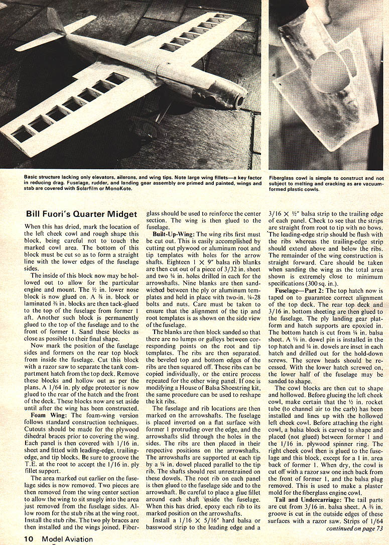
Install a 1/16 x 5/16 in. hard balsa strip to the leading edge and a 3/16 x 1/2 in. balsa strip to the trailing edge of each panel. Check to see that the strips are straight from root to tip with no bows. The leading-edge strip should be flush with the ribs whereas the trailing-edge strip should extend above and below the ribs. The remainder of the wing construction is straight forward. Care should be taken when sanding the wing as the total area shown is extremely close to minimum specifications (300 sq. in.).
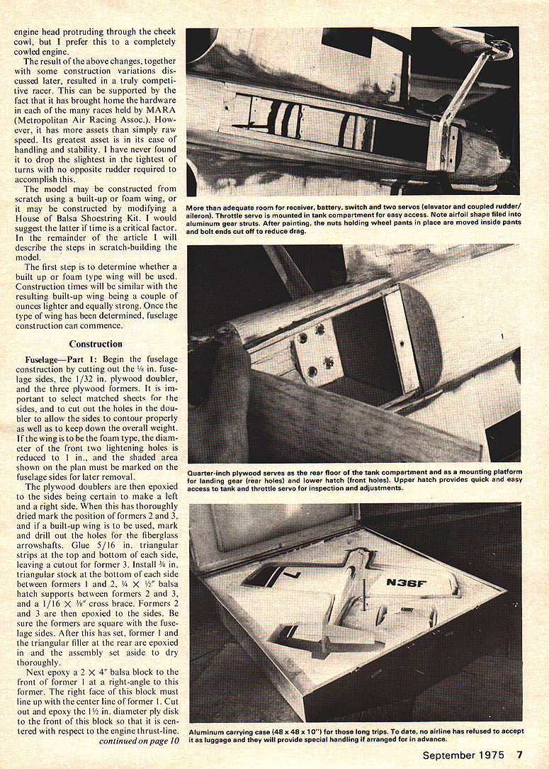
Fuselage—Part 2: The top hatch now is taped on to guarantee correct alignment for gluing the top deck. The rear top deck and 3/16 in. bottom sheet are then glued to the fuselage. The ply landing gear platform and hatch supports are epoxied in. The bottom hatch is cut from 1/8 in. balsa sheet. A 1/8 in. dowel pin is installed in the top hatch and 1/4 in. dowels are inset in each hatch and drilled out for the hold-down screws. The screw heads should be recessed. With the lower hatch screwed on, the lower half of the fuselage may be glued to the top.
The cowl blocks are then cut to shape and hollowed. Before gluing the left cheek block, make certain that the 1/2 in. notch in the cowl has been cut so the carburetor will line up with the hollowed left cheek cowl. Before attaching the right cheek cowl, a balsa block is carved to shape and placed between former 1 and 2. The 1/16 in. plywood spinner ring is glued to the fuselage and this block, except for a 1/8 in. area cut off with a razor saw one inch back from the front of former 1, and the block may be removed. This is used to make a plaster mold for the fiberglass engine cowl.
Tail and Undercarriage: The tail parts are cut from 3/16 in. balsa sheet. A 1/8 in. groove is cut in the outside edges of these surfaces with a razor saw. Strips of 1/64 in. ... ply are glued into this groove to protect the edges of the surfaces. The surfaces then can be sanded to shape as shown on the plans, and the elevators and lower portion of the rudder cut off and hinged. The rudder and stab are then epoxied to the fuselage. A canopy is added, making certain that a minimum fuselage height of 5 in. is maintained. Fillets then are installed on the wing, tail, canopy, and cowls, using microballoons.
The wheel pants now are constructed and the entire airplane is final sanded. It is suggested that the aluminum landing gear struts be filed to an airfoil shape, particularly at the leading edge. The fuselage, rudder and wheel pants should now be given a coat of resin and a coat of epoxy filler with a sanding after each. The fuselage is then given one light coat of epoxy paint. The wing and stab should be covered with Monokote or Solar Film.
Equipment: I have found that coupled aileron and rudder works fine without problems. Therefore, it is only necessary to have two servos within the fuselage—aileron/rudder and elevator. The engine servo is mounted in the tank compartment to the right side of the fuselage. For proper balance, the receiver and battery pack should be mounted against former 2. The tank is a four oz. Sullivan slant type.
Flying: The airplane will prove to be responsive but stable if you adhere to the CG location and control surface deflections indicated on the plan. I find that, with this set up, it will turn on a dime without the slightest snap roll tendency. The tightest of turns will cause no structural damage if the all-up weight of the model does not exceed 3-1/2 pounds. However, if your plane weighs more than this, I would suggest that you do not whip, but smoothly and gently turn around pylon 1. The five of these ships that I've built (all still in existence) ranged in weight from 40 oz. to 42 oz. Well, I guess that's about it, the rest is up to you, your engine, and your radio.
Transcribed from original scans by AI. Minor OCR errors may remain.

