
Bipe '89
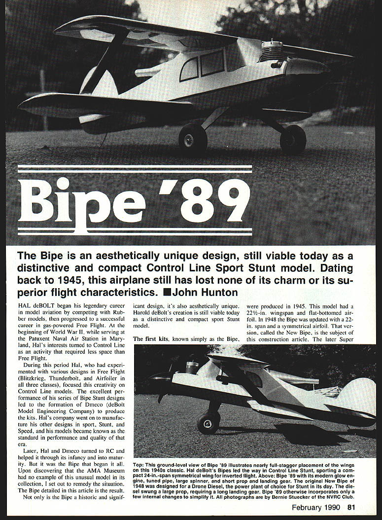
The Bipe is an aesthetically unique design, still viable today as a distinctive and compact Control Line Sport Stunt model. Dating back to 1945, this airplane has lost none of its charm or its superior flight characteristics. — John Hunton
Hal deBolt began his legendary career in model aviation by competing with rubber models, then progressed to a successful career in gas-powered Free Flight. At the beginning of World War II, while serving at the Patuxent Naval Air Station in Maryland, Hal's interests turned to Control Line as an activity that required less space than Free Flight.
During this period Hal, who had experimented with various designs in Free Flight (Blitzkrieg, Thunderbolt, and Airfoiler in all three classes), focused his creativity on Control Line models. The excellent performance of his series of Bipe Stunt designs led to the formation of Dmeco (deBolt Model Engineering Company) to produce kits. Hal's company went on to manufacture his other designs in Sport, Stunt, and Speed, and his models became known as the standard in performance and quality of that era.
Later, Hal and Dmeco turned to RC and helped it through its infancy and into maturity. But it was the Bipe that began it all. Upon discovering that the AMA Museum had no example of this unusual model in its collection, I set out to remedy the situation. The Bipe detailed in this article is the result.
Not only is the Bipe a historic and significant design, it's also aesthetically unique. Harold deBolt's creation is still viable today as a distinctive and compact Sport Stunt model.
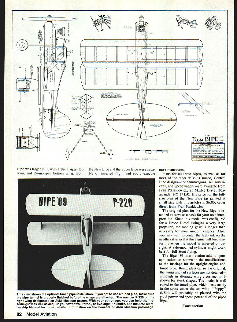
The first kits, known simply as the Bipe, were produced in 1945. This model had a 22-1/2 in. wingspan and a flat-bottomed airfoil. In 1948 the Bipe was updated with a 22 in. span and a symmetrical airfoil. That version, called the New Bipe, is the subject of this construction article. The later Super Bipe, larger still, had a 28 in. span top wing and a 24 in. span bottom wing. Both the New Bipe and Super Bipe were capable of inverted flight and could execute full Stunt maneuvers.
Plans for the three Bipes, as well as other deBolt/Dmeco Control Line designs — the Stuntwagons and American Speedwagons — are available from Fran Ptaszkiewicz:
- Address: 23 Marlee Drive, Tonawanda, NY 14150
- Price: full-size plan; New Bipe printed small-size article $6.00
- Order direct from Fran Ptaszkiewicz.
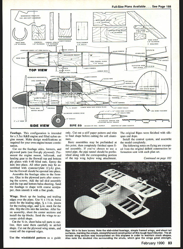
The original New Bipe plan tended to serve as the basis for one's own interpretation. Since the model was configured for a Drone Diesel swinging a very large propeller, the long landing gear is not necessary with modern engines. You may also want to center the fuel tank and needle valve so the engine will feed uniformly inverted or upright; a side-mounted cylinder might work best for full Stunt flying. The Bipe '89 interpretation adds a sport application with an upright engine and tuned pipe. Otherwise the wings and tail surfaces remain identical to the original plans, although an alternate wing cross section is shown. The stock shapes of the model are well suited, and a tuned pipe nests neatly in the space under the top wing. Pappy deBolt would probably be pleased with the good power and speed potential of the piped Bipe.
Construction
The fuselage is built in two halves over the plan. Cut the sides and formers, install the longerons, and glue the formers to the sides. Fit the firewall and nose ring (1/8 in. plywood) and install the engine bearers. Join the two halves, cement and sand to outline, then sheet the top and bottom where shown.
The wings are built flat on the plan. Use the stock rib and spar shapes shown; the top wing has the full stagger as drawn. Build the center section and add the outer panels. Fit the interplane and center-section struts and check incidence before final sanding and covering.
Tail surfaces are cut from the stock shapes shown on the plan. Hinge and fit the rudder and elevator, then install the control linkage with proper throw and balance.
Landing gear is formed from the size wire shown on the plan and anchored to the plywood mount. Fair the gear with balsa and fit wheels and wheel pants as desired.
If using a tuned pipe, install the pipe tunnel and mount the pipe before the wings are attached so the finish is complete and the pipe clearances are correct. Balance the model per the plan, install the radio or control system, finish, and trim for flight.
Fuselage
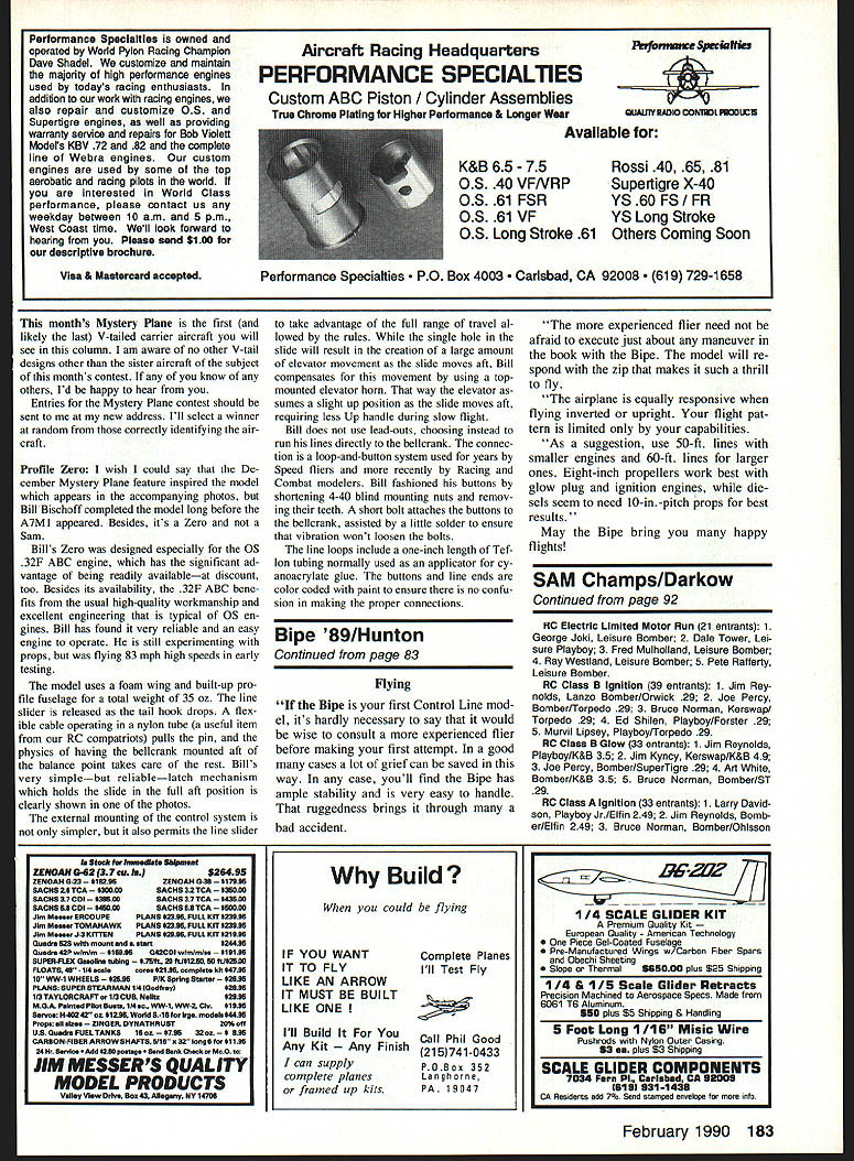
This configuration is intended for a 3.5 cc K&B engine and filled nylon engine mount. Make design modifications as required for your own engine/mount combination.
Cut out the fuselage sides, formers, and plywood parts (use five-ply plywood). Pre-mount the engine mount, bellcrank, and landing gear to the firewall top and bottom ply plates with 4-40 blind nuts. Epoxy the nuts into place. All other parts may be assembled with cyanoacrylate (CyA) glue, but the firewall should be epoxied into place.
Assemble the fuselage sides to the formers. Glue in the plywood parts after removing the screws. Add the tail skid assembly, and the top and bottom balsa sheeting. Sand the fuselage to shape with coarse sandpaper, then smooth it with a fine grade.
Wings
Block up the leading and trailing edges over the plans. Use 1/2 x 1/4 in. balsa stock for the leading edge, 3/32 x 1/8 in. pieces for the trailing edge, and 1/8 in. stock for the ribs. Slip the ribs into the notches. After basic assembly, sheet the center sections and install the tip blocks. Sand the wings to accurate airfoil shape.
Cut the 1/4 in. sheet balsa tail parts to outline, then sand them carefully to airfoil shape. Cut out the plywood wing struts, and round off the exposed edges.
Use the windshield pattern as a guide only. Cut out a stiff paper pattern and trim to final shape before cutting the soft aluminum.
Basic assemblies may be prefinished at this point, then completely finished upon final assembly. If you've chosen to use a tuned pipe, the pipe tunnel should be prefinished along with the corresponding portion of the top wing before wing attachment.
The original Bipes were finished with silkspan and dope.
Install the control system, and assemble the model completely.
The following notes on flying are excerpted from the original deBolt construction information sent with each plan set.
Bipe '89/Hunton
Continued from page 83
Flying
"If the Bipe is your first Control Line model, it's hardly necessary to say that it would be wise to consult a more experienced flier before making your first attempt. In a good many cases a lot of grief can be saved in this way. In any case, you'll find the Bipe has ample stability and is very easy to handle. That ruggedness brings it through many a bad accident.
"The more experienced flier need not be afraid to execute just about any maneuver in the book with the Bipe. The model will respond with the zip that makes it such a thrill to fly.
"The airplane is equally responsive when flying inverted or upright. Your flight pattern is limited only by your capabilities.
"As a suggestion, use 50-ft lines with smaller engines and 60-ft lines for larger ones. Eight-inch propellers work best with glow plug and ignition engines, while diesels seem to need 10-in pitch props for best results."
May the Bipe bring you many happy flights!
Transcribed from original scans by AI. Minor OCR errors may remain.

