

Black Beauty
This design for the Unlimited class of Slope Soaring Racing was created to win. Though some qualified observers have opined that, with some modifications, it would also be competitive in FAI F3B events, I don't know. All I want to do is race with it.
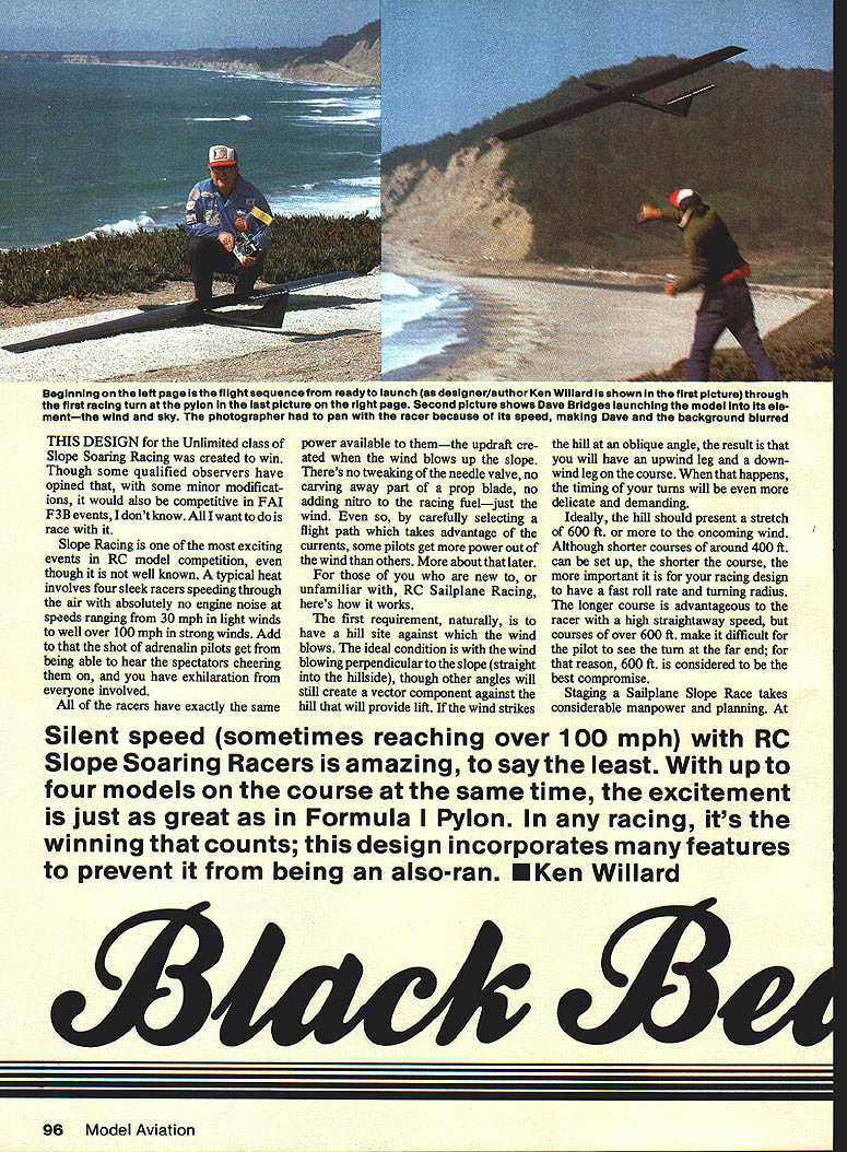
Slope racing is one of the most exciting events in RC model competition, even though it is not well known. A typical heat involves four sleek racers speeding through the air with absolutely no engine noise at speeds ranging from 30 mph in light winds to well over 100 mph in strong winds. Add to that the shot of adrenaline pilots get from being able to hear the spectators cheering them on, and you have exhilaration for everyone involved.
All of the racers have exactly the same power available to them—the updraft created when the wind blows up the slope. There's no tweaking of the needle valve, no carving away part of a prop blade, no adding nitro to the racing fuel—just the wind. Even so, by carefully selecting a flight path that takes advantage of the currents, some pilots get more power out of the wind than others.
Slope racing overview
For those who are new to, or unfamiliar with, RC sailplane racing, here's how it works.
The first requirement is to have a hill site against which the wind blows. The ideal condition is with the wind blowing perpendicular to the slope (straight on the hillside), though other angles will still create a vector component against the hill that will provide lift. If the wind strikes the hill at an oblique angle, the result is that you will have an upwind leg and a downwind leg on the course. When that happens, the timing of your turns becomes even more delicate and demanding.
Ideally, the hill should present a stretch of 600 ft. or more to the oncoming wind. Although shorter courses of around 400 ft. can be set up, the shorter the course, the more important it is for your racing design to have a fast roll rate and small turning radius. The longer course is advantageous to the racer with a high straightaway speed, but courses over 600 ft. make it difficult for the pilot to see the turn at the far end; for that reason, 600 ft. is considered the best compromise.
Staging a sailplane slope race takes considerable manpower and planning. At the end of the course you typically need:
- Four flagmen
- A pylon judge
- A start-line and finish judge
- An official starter
- A communication system between the pilots' area and the far pylon line
- A whip man to get contestants for upcoming races ready at the line
- A weight man to check racers against the allowable maximum (at the end of a race a racer may jettison ballast)
- A copilot/pitman to call turns for the pilot at the far end of the course
Some tasks can be performed by pilots competing in the immediate race, but you can see how much manpower is needed.
Silent speed (sometimes reaching over 100 mph) with RC slope soaring racers is amazing. With up to four models on the course at the same time, the excitement is just as great as in Formula I pylon. In any racing, it's the winning that counts; this design incorporates many features to prevent it from being an also-ran.
Let's take a look at the course as shown in the schematic diagram (Fig. 1). Note that all flying is done out in front of the pylon aiming stakes; you do not fly around the pylon, but past the aiming line at the pylon. Since all turns are made into the wind, the flight path is a figure 8, and that can present problems when two aircraft are flying the course—one going upwind and the other downwind. Some guys call that a "demolition derby," but surprisingly most midair collisions are at the turn rather than at the crossover point.
"Sailboat" race starts are used, and they can be quite exciting. One minute before the actual start of the race, a countdown begins. The aircraft can be launched at any time prior to 15 seconds before the start. The pilot then orbits his model wherever he chooses to gain altitude, but when the countdown ends the racers must be behind the start line.
Pilots in these events have developed numerous strategies and techniques to get a jump on the competition:
- Some stay well back of the start line and approach it in a timed dive.
- Others get right above the start line, headed out away from the hill, and make a diving turn to the line.
- Still others position their models ahead of and high above the line, coming downwind to do a Split-S into the start.
With all of these methods, timing is a split-second thing, as the diving speeds are right around 100 mph.
Flagmen on the pylon line are critical to the success of the race. Each one has a different flag which has been identified to the pitman of a specific racer. When the race starts, the flagman at the far turn holds up their flags; when the nose of the racer crosses the sighting line, the flag is dropped and the pitman calls "Turn!" to his pilot. Some skilled pilots can even judge the distance and begin a turn before the flag drops; that's all right so long as the racer goes past the pylon line.
If no part of the racer passes the sighting line, the flagman waves a cut, and the pilot has to fly an extra lap. That usually results in a last-place finish if the race is really close.
The near pylon is only about 30 ft. from the pilots' box, so most pilots execute the near turn without prompting. Nonetheless, flagmen operate in the same manner as at the distant pylon. The pylon judge at each pylon can overrule the flagman if, in his judgment, a cut has been incorrectly called in the excitement of a race. The flagman must wait until the nose of the racer is past the sight line; any sooner would give an unfair advantage.
Races can be five, eight, or even ten laps, depending on conditions and the Contest Director's decision. The end of the race must be made with the sailplanes going in the same direction as at the start, so a final turn is made just before crossing the finish line. As you might guess, many a race has been decided on that turn.
The matrix for sailplane slope racing is established in the same manner as for engine-powered pylon races. I won't go into the details other than to note a variation used in the International Slope Races: on the second day there usually is some seeding so that pilots with top scores who, through luck of the draw, have not competed against each other are purposely put into races together to balance out luck.
Over the years the International Slope Races have set a rule that at least four rounds of flying must be completed; if more than four rounds are flown, one round may be selected by each pilot to be dropped from his score. This provides some compensation for the bad luck of a midair collision or not finishing the race because the wind dropped (while others managed to stay aloft).
Scoring is simple:
- 1 point for first
- 2 points for second
- 3 points for third
- 4 points for fourth
- 5 points for a DNF (did not finish)
- 6 points for a DNS (did not start)
The one with the lowest score is the winner; ties are flown off.
FAI limits are used. In English equivalents this means a maximum total weight of 11 lb. and a maximum surface loading of 24 oz./sq. ft. (combined wing and tail surface area).
Wind conditions can vary from light—where a typical competitive racer can barely remain aloft—to winds as high as 50 mph. With this in mind, it is imperative that the racer be competitive throughout the complete spectrum of wind conditions.
In addition to handling a wide range of wind conditions, a sailplane slope racer has to be rugged enough to take rough landings and keep going. Most slope sites do not have a smooth stretch of landing area, and when the wind is blowing hard, turbulence makes smooth landings difficult at best.
Design objectives and features
How do you design a racer to meet all these conditions? It's a real challenge, and there are several approaches. The design of the Black Beauty is the one I came up with. Theoretically, it should meet all the requirements for a completely versatile racer.
The only race it had been in when this was written was the 1984 International Slope Races; as luck would have it, wind conditions were such (from 20 to 50 mph) that its potential light-air performance was not demonstrated in competition. I do know, however, that it can stay aloft even in the lightest winds.
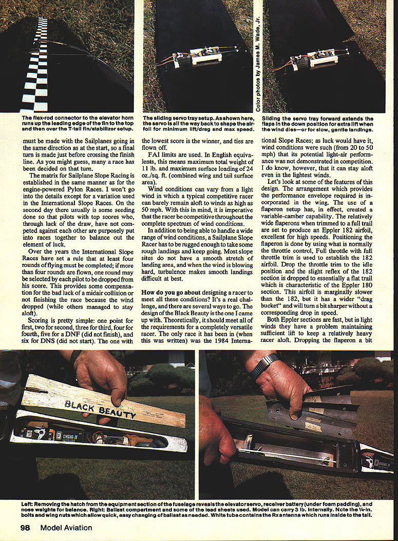
Key features are incorporated in the wing. The use of a flaperon setup has, in effect, created a variable-camber capability. The relatively wide flaperons, when trimmed to full trail, are set to produce an Eppler 182 airfoil—excellent for high speeds. Positioning the flaperon is done by using what is normally the throttle control. Full throttle with full throttle trim is used to establish the 182 airfoil. Drop the throttle trim to the idle position and the slight reflex of the 182 section is reduced to essentially a flat trail, characteristic of the Eppler 180 section. This airfoil is marginally slower than the 182 but has a wider "drag bucket" and will turn a bit sharper without a corresponding drop in speed.
Both Eppler sections are fast, but in light winds they have a problem maintaining sufficient lift to keep a relatively heavy racer aloft. Dropping the flaperon a bit gives the wing additional camber and the lift needed in light air. More, however, creates an undercambered section similar to the NACA 6709— not too fast but able to stay up when other racers are struggling.
Finally, when landing, the flaperons can be dropped even further until, just before touchdown, they are at about 45°. This slows the landing speed drastically, but at the full-down position there is noticeable adverse yaw when you apply aileron control. Be careful not to drop the flaperons too far too soon—it takes some practice.
I use the T-tail for two reasons:
- It results in only two joining angles (instead of four) between the fin and the stab, which gives less drag.
- The high-mounted stab is less likely to be knocked off on landing.
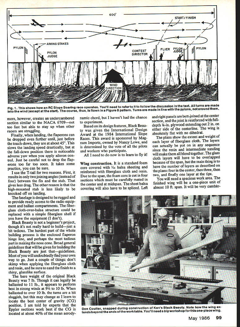
The fuselage is designed to be rugged and to provide ready access to the radio equipment and ballast compartments. The fiberglass cloth-over-balsa structure could be replaced with a simple fiberglass shell if you have the equipment.
Black Beauty is not a beginner's project, though it's not really hard to build—just a bit tedious. The hardest part of the whole building process is the enclosed flaperon hinge line, and perhaps the most tedious part is making the nose cone. The guidelines given here are just that—guidelines. Most builders will find their own way to go. A couple of cautions: don't skimp when applying the fiberglass cloth and resin, and be sure to sand the finish to a shiny, glasslike surface.
The bare weight of the original Black Beauty was 7 lb. Though it can legally be ballasted to 11 lb., it appears to perform best in strong winds at 9½ to 10 lb. When ballasted over 10 lb. the turns are a bit sluggish, but this may change with further CG experiments. Experts suggest Eppler sections work best if the CG is located at about the mean aerodynamic chord, but I haven't had the chance to experiment.
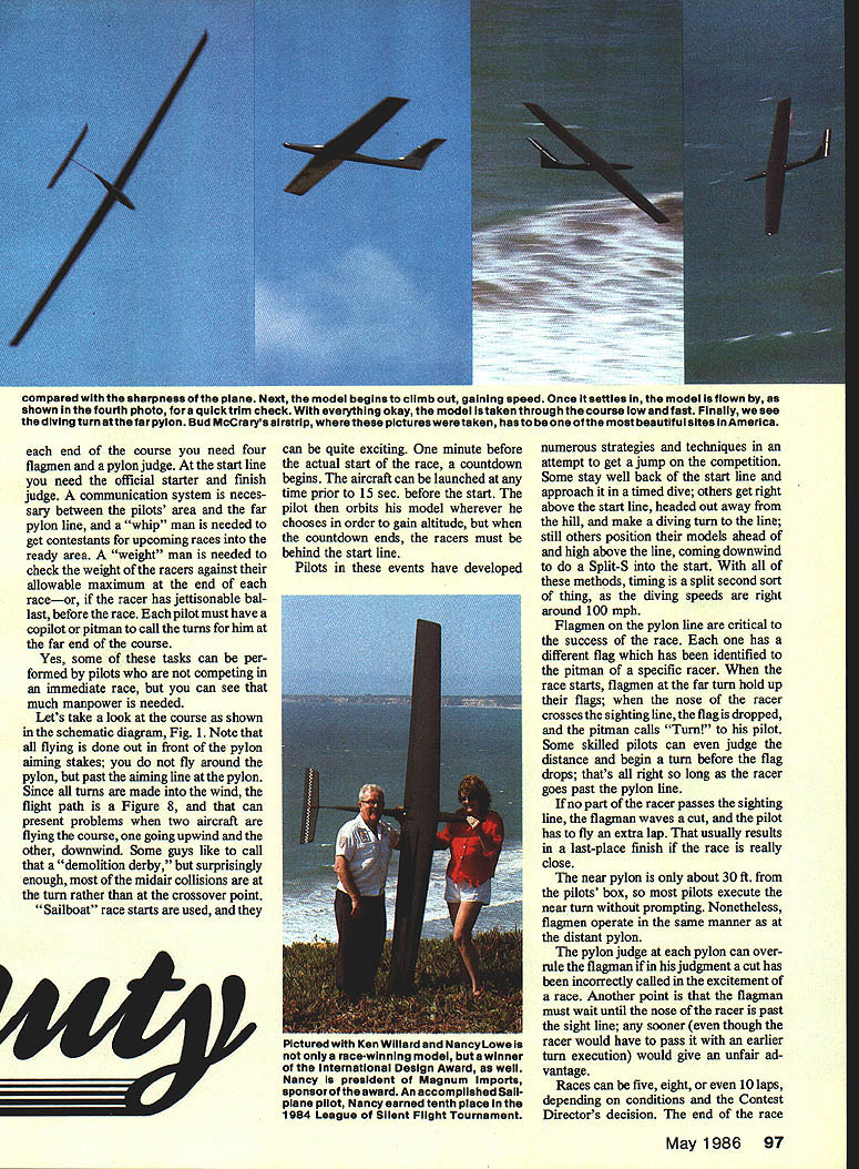
Based on its design features, Black Beauty was given the International Design Award at the 1984 International Slope Races. This award is sponsored by Magnum Imports (owned by Nancy Lowe) and is determined by the vote of all the pilots and workers who participate.
All I need to do now is learn to fly it!
Wing construction
The wing is a standard foam core covered with 1/16-in. balsa sheeting and reinforced with fiberglass cloth and resin. Due to the span, the foam core is cut in four sections which must be carefully mated in the center and at midspan. The sheet balsa covering will also have to be spliced. Left and right panels are butt-jointed at the center section, and the joint is reinforced with full-depth 1/8-in. plywood extending out 2 in. on either side of the centerline. The wing is absolutely flat with no dihedral.
The plans show the extent and weight of each layer of fiberglass cloth. The layers can be put on in any sequence since the resin and intermediate sanding will make them blend together. The glass cloth layers will have to be overlapped because of the span, but the main thing is to have the number of layers as described on the plans:
- Four layers in the center
- Then three layers
- Then two layers
- Finally one layer at the tips
You will need a spacious work area. The finished wing will be a one-piece unit of almost 10 ft. span. It will be very cumbersome to handle, but the great strength is worth it.
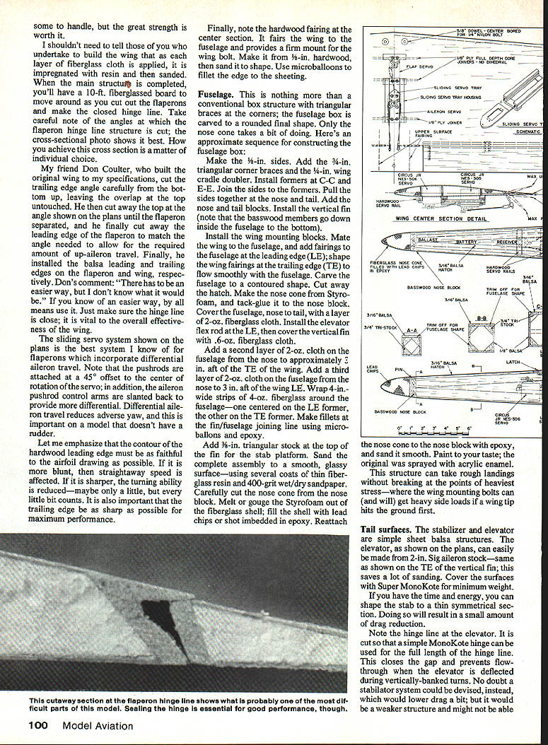
As each layer of fiberglass cloth is applied, it is impregnated with resin and then sanded. When the main structure is completed, you'll have a 10-ft. fiberglassed board to work on as you cut out the flaperons and make the enclosed hinge line. Take careful note of the changes at which the flaperon hinge line structure is cut; the cross-sectional photo (on the plans) shows it best. How you achieve the cross section is a matter of individual choice.
My friend Don Coulter, who built the original wing to my specifications, cut the trailing edge angle carefully from the bottom up, leaving the overlap at the top untouched. He then cut away the top at the angle shown on the plans until the flaperon separated, and he finally cut away the leading edge of the flaperon to match the angle needed to allow for the required amount of up-aileron travel. Finally, he installed the balsa leading and trailing edges on the flaperon and wing, respectively. Don's comment: "There has to be an easier way, but I don't know what it would be." If you know an easier way, by all means use it. Just make sure the hinge line is close; it is vital to the overall effectiveness of the wing.
The sliding servo system shown on the plans is the best system I know of for flaperons that incorporate differential aileron travel. Note that the pushrods are attached at a 45° offset to the center of rotation of the servo; in addition, the aileron pushrod control arms are slanted back to provide more differential. Differential aileron travel reduces adverse yaw, and this is important on a model that doesn't have a rudder.
Emphasize that the contour of the hardwood leading edge must be as faithful to the airfoil drawing as possible. If it is more blunt, straightaway speed is affected. If it is sharper, turning ability is reduced—maybe only a little, but every little bit counts. It is also important that the trailing edge be as sharp as possible for maximum performance.
Finally, note the hardwood fairing at the center section. It fairs the wing to the fuselage and provides a firm mount for the wing bolt. Make it from 3/8-in. hardwood, then sand it to shape. Use microballoons to fillet the edge to the sheeting.
Fuselage
The fuselage is a conventional box structure with triangular braces at the corners; the fuselage box is carved to a rounded final shape. Only the nose cone takes a bit of doing. Here's an approximate sequence for constructing the fuselage box:
- Make the 3/8-in. sides. Add the 3/4-in. triangular corner braces and the 1/4-in. wing cradle doubler.
- Install formers at C-C and E-E. Join the sides to the formers.
- Pull the sides together at the nose and tail. Add the nose and tail blocks.
- Install the vertical fin (note that the basswood members go down inside the fuselage to the bottom).
- Install the wing mounting blocks. Mate the wing to the fuselage, and add fairings to the fuselage at the leading edge (LE); shape the wing fairings at the trailing edge (TE) to flow smoothly with the fuselage.
- Carve the fuselage to a contoured shape. Cut away the hatch.
- Make the nose cone from Styrofoam, and tack-glue it to the nose block.
- Cover the fuselage, nose to tail, with a layer of 2-oz. fiberglass cloth. Install the elevator flex rod at the LE, then cover the vertical fin with 0.6-oz. fiberglass cloth.
Add a second layer of 2-oz. cloth on the fuselage from the nose to approximately 3 in. aft of the TE of the wing. Add a third layer of 2-oz. cloth on the fuselage from the nose to 3 in. aft of the wing LE. Wrap 4-in.-wide strips of 4-oz. fiberglass around the fuselage—one centered on the LE former, the other on the TE former. Make fillets at the fin/fuselage joining line using microballoons and epoxy.
Add 3/8-in. triangular stock at the top of the fin for the stab platform. Sand the complete assembly to a smooth, glassy surface—using several coats of thin fiberglass resin and 400-grit wet/dry sandpaper. Carefully cut the nose cone from the nose block. Melt or gouge the Styrofoam out of the fiberglass shell; fill the shell with lead chips or shot embedded in epoxy. Reattach the nose cone to the nose block with epoxy, and sand it smooth. Paint to your taste; the original was sprayed with a thick acrylic enamel.
This structure can take rough landings without breaking at the points of heaviest stress—where the wing mounting bolts are and where they can get heavy side loads if a wing tip hits the ground first.
Tail surfaces
The stabilizer and elevator are simple sheet-balsa structures. The elevator can easily be made from 2-in. Sig aileron stock—same as shown on the TE of the vertical fin; this saves a lot of sanding. Cover the surfaces with Super MonoKote for minimum weight.
If you have the time and energy, you can shape the stab to a thin symmetrical section; doing so will result in a small amount of drag reduction.
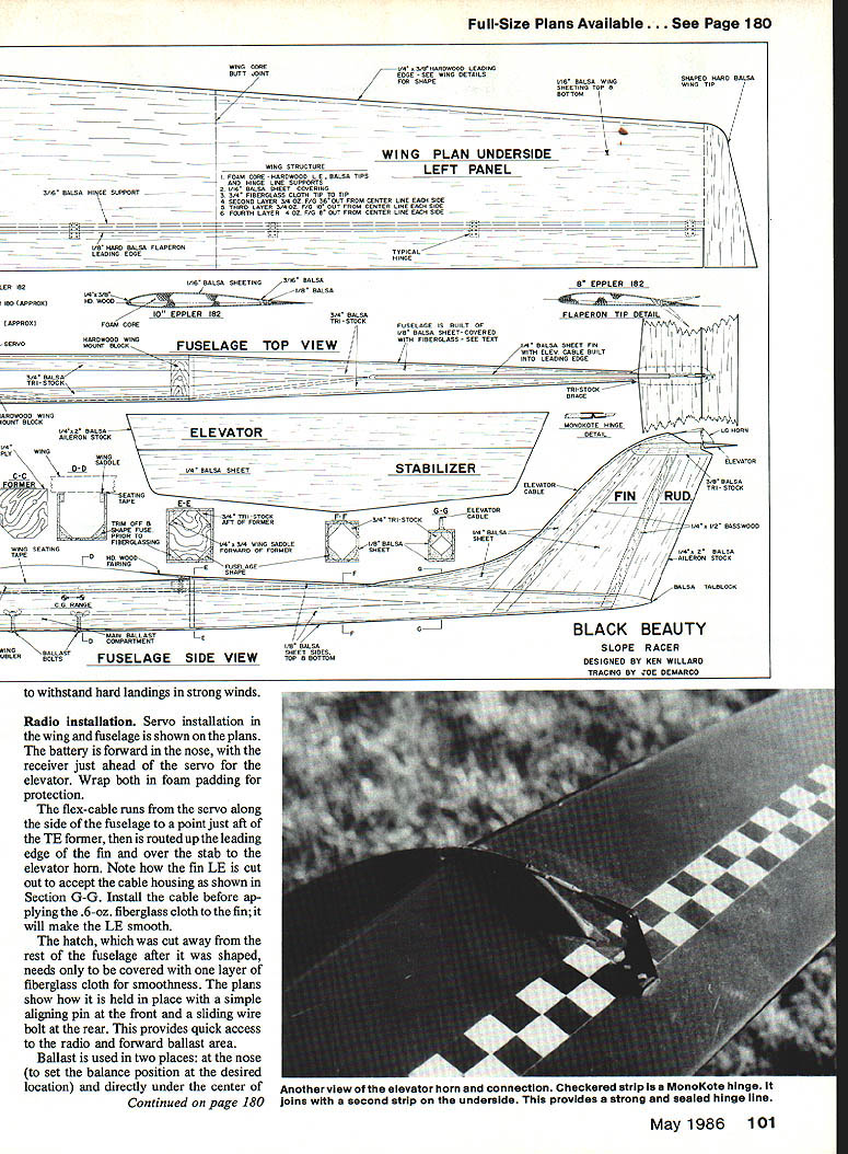
Note the hinge line at the elevator. It is cut so that a simple MonoKote hinge can be used for the full length of the hinge line. This closes the gap and prevents flow-through when the elevator is deflected during vertically banked turns. A stabilator system could be devised instead, which would lower drag a bit; but it would be a weaker structure and might not withstand hard landings in strong winds.
Radio installation
Servo installation in the wing and fuselage is shown on the plans. The battery is forward in the nose, with the receiver just ahead of the servo for the elevator. Wrap both in foam padding for protection.
The flex-cable runs from the servo along the side of the fuselage to a point just aft of the TE former, then is routed up the leading edge of the fin and over the stab to the elevator horn. Note how the fin LE is cut out to accept the cable housing as shown in Section G-G. Install the cable before applying the 6-oz. fiberglass cloth to the fin; it will make the LE smooth.
The hatch, which was cut away from the rest of the fuselage after it was shaped, needs only one layer of fiberglass cloth for smoothness. The plans show how it is held in place with a simple aligning pin at the front and a sliding wire bolt at the rear. This provides quick access to the radio and forward ballast area.
Ballast is used in two places:
- At the nose (to set the balance position at the desired location)
- Directly under the center of balance (so that weight can be added for high-wind conditions without changing the CG location)
I use lead sheet cut into various sizes and weights; this is held in place with bolts and wing nuts, permitting rapid changes in ballast as wind conditions dictate.
Flying
What a thrill! With all systems checked out and working, have a qualified associate launch your Black Beauty into the wind with the nose slightly down so that it will pick up speed rapidly. Be ready. The air will be surprisingly cool where the wind is light; then, as it reaches flying speed for level flight, the nose will come up, and the racer will be sliding through the air silently and swiftly.
You may have to make some minor trim adjustments. Fly it each time to check out the control responses. As you get used to the sight of the model flashing through the air, you can start making small turns, putting the nose down and going to high-speed flight.
Sensitivity of the controls is a matter of individual taste. I set mine up so that when my pitman calls "Turn!" I can use full throw on the ailerons without over-throwing the elevator. Also, the elevator is set so that when held gently in the up position a stall is established in the racing turn; full-up can be used without causing a high-speed snap. The reason for this is obvious: in the heat and excitement of a race, pilots can over-roll into a Split-S or pull such a tight turn with their elevator that a snap roll results. If the surfaces are set so they won't go that far, the danger is reduced.
Flying a slope race course is a skill in itself. Each location will have its own characteristics, but several general concepts apply. Under normal wind conditions, if you fly out too far from the hill the vertical component of the wind will be less, and you can't "push" it. If you fly too close to the hill, surface turbulence can throw you out of your race line. Only practice time can help you locate the area of best lift.
If the wind is blowing at an oblique angle to the hill, you usually can improve your lap speed by flying the upwind leg farther out and the downwind leg closer in. Reason: the closer to the hill an "angled" wind gets, the more the vector is parallel to the hill, and this reduces lift but increases the tailwind vector. Which aspect is important depends on the particular site. Again, practice is the answer.
Slope racing is the most exciting RC event I know of, and Black Beauty is the most exciting racer I've ever had. I hope you enjoy your races as much as I do mine.
Transcribed from original scans by AI. Minor OCR errors may remain.

