
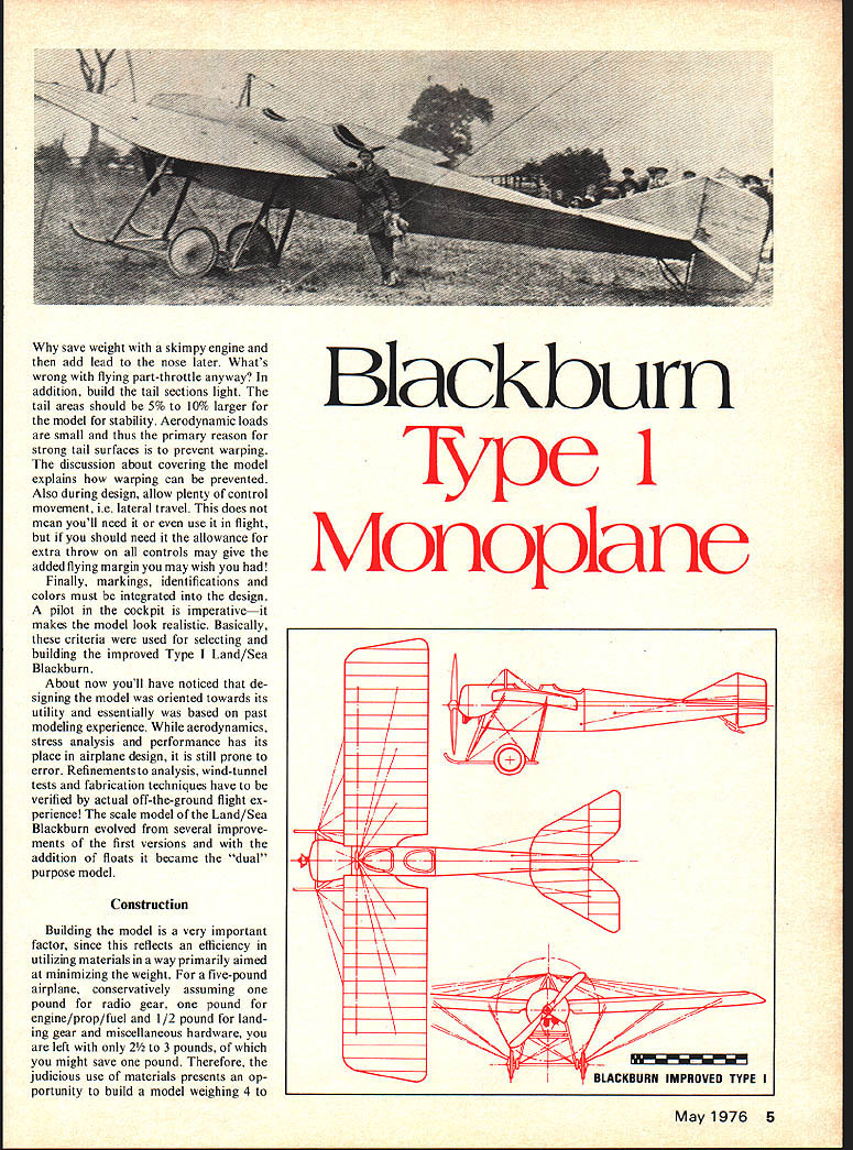
Blackburn Type 1 Monoplane
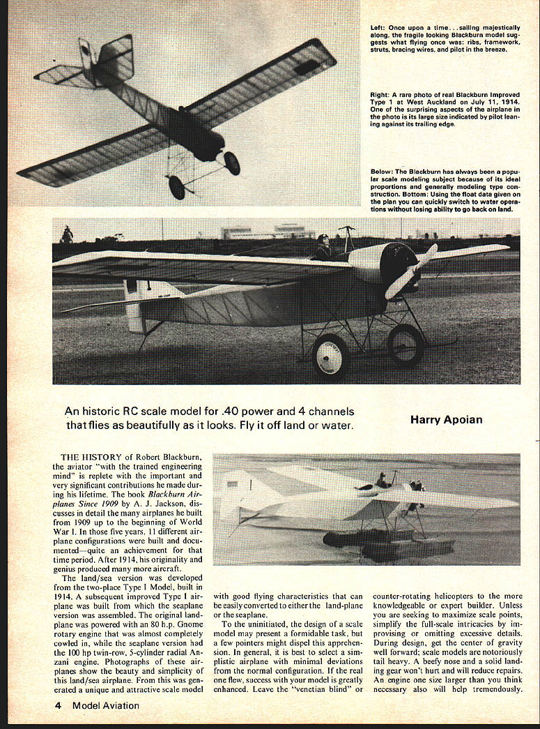
An historic RC scale model for .40 power and 4 channels that flies as beautifully as it looks. Fly it off land or water.
Harry Apoian
THE HISTORY of Robert Blackburn, the aviator "with the trained engineering mind" is replete with the important and very significant contributions he made during his lifetime. The book Blackburn Airplanes Since 1909 by A. J. Jackson discusses in detail the many airplanes he built from 1909 up to the beginning of World War I. In those five years, 11 different airplane configurations were built and documented—quite an achievement for that time period. After 1914, his originality and genius produced many more aircraft.
The land/sea version was developed from the two-place Type I model, built in 1914. A subsequent improved Type I airplane was built from which the seaplane version was assembled. The original landplane was powered with an 80 h.p. Gnome rotary engine that was almost completely cowled in, while the seaplane version had the 100 h.p. twin-row, 5-cylinder radial Anzani engine. Photographs of these airplanes show the beauty and simplicity of this land/sea airplane. From this was generated a unique and attractive scale model with good flying characteristics that can be easily converted to either the landplane or the seaplane.
To the uninitiated, the design of a scale model may present a formidable task, but a few pointers might dispel this apprehension. In general, it is best to select a simplistic airplane with minimal deviations from the normal configuration. If the real one flew, success with your model is greatly enhanced. Leave the "venetian blind" or counter-rotating helicopters to the more knowledgeable or expert builder. Unless you are seeking to maximize scale points, simplify the full-scale intricacies by improvising or omitting excessive details.
During design, get the center of gravity well forward; scale models are notoriously tail heavy. A beefy nose and a solid landing gear won't hurt and will reduce repairs. An engine one size larger than you think necessary also will help tremendously.
Also save weight—don't skimp the engine and add lead to the nose later. What's wrong with flying part-throttle anyway? In addition, build tail sections light; tail areas should be 5% to 10% larger for stability. Aerodynamic loads are small; thus the primary reason is to have strong tail surfaces to prevent warping. A discussion about covering the model explains how warping can be prevented. Also, during design allow plenty of control movement (i.e., lateral travel). This does not mean you'll need to use the extra travel in flight, but allowance of extra throw in the controls may give added flying margin you may wish.
Finally, markings, identifications and colors must be integrated into the design—the pilot and cockpit are imperative; they make the model look realistic. Basically, the criteria used in selecting and building the improved Type land/sea Blackburn...
Construction
Building the model is a very important factor, since this reflects an efficiency in utilizing materials in a way primarily aimed at minimizing the weight. For a five-pound airplane, conservatively assuming one pound for radio gear, one pound for engine/prop/fuel and 1/2 pound for landing gear and miscellaneous hardware, you are left with only 2 1/2 to 3 pounds, of which you might save one pound. Therefore, the judicious use of materials presents an opportunity to build a model weighing 4 to weighing 4 to 4-1/2 pounds.
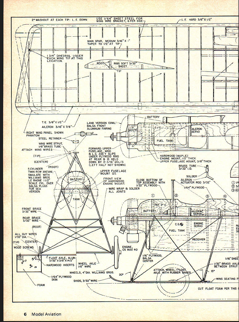
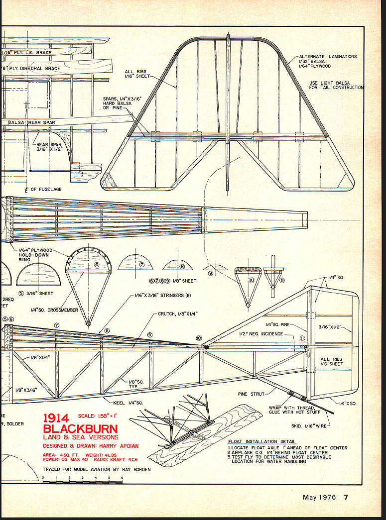
1914 BLACKBURN LAND & SEA VERSIONS
DESIGNED & DRAWN: HARRY APOLAN
AREA: 49 SQ. FT. WEIGHT: 4 LBS POWER: O.S. MAX 40 RADIO: KRAFT 4CH
TRACED FOR MODEL AVIATION BY RAY BORDEN
FLOAT INSTALLATION DETAIL
- LOCATE FLOAT AXLE 1" AHEAD OF FLOAT CENTER
- AIRPLANE C.G. 1/4" BEHIND FLOAT CENTER
- TEST FLY TO DETERMINE MOST DESIRABLE LOCATION FOR WATER HANDLING
Blackburn Monoplane
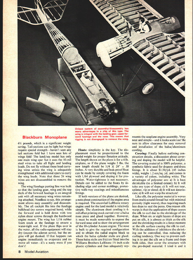
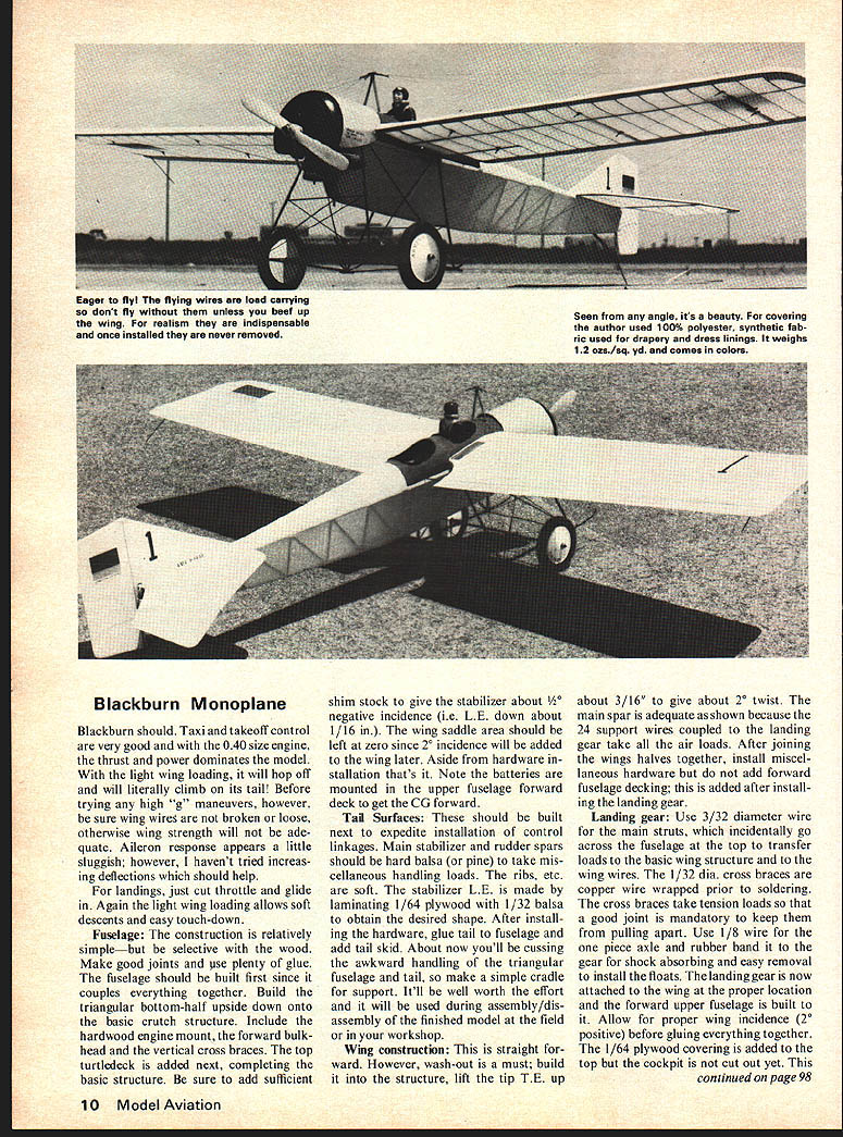
4½ pounds, which is a significant weight saving. Tail sections can be light but wings require special strength—haven't seen any tail sections fold but I have seen lots of wings fold! The land/sea model has only one main wing spar but it uses the 10-mil steel wires to take all flight and landing loads. Do not fly without those load-carrying wires unless the wing is adequately strengthened with additional spars to carry the wing loads. Note that these 24 wing wires are not disassembled to remove the wing.
The wing/fuselage parting line was built so that the landing gear, wing and the top deck of the forward fuselage is an integral unit with all necessary wing wires remaining attached. Needless to say, this arrangement allows easy assembly and disassembly. The aft cockpit fits into the fuselage bulkhead (no screws required here), while the forward end is held down with two nylon shear screws through the hardwood engine mount. The wing has 1/16 rubber foam stuck at the fuselage to ensure a water-tight seal. If the plane flips over in the water, all the radio equipment will stay dry (except the aileron servo), but the engine will get dunked. If that happens run engine immediately to evaporate and remove all water—it's a nasty mess if you don't.
Floats: simplicity is the key. The displacement must be proportioned to the model weight for proper flotation attitude. The length shown on the plans is for a 4-lb airplane, so if the plane weighs 5 lbs, the new length should be 5/4 × 24" = 30 inches. A very durable and leak-proof float can be made by simply covering the foam with 1/64 plywood and doping it for protection. Water-tightness is not necessary. Details can be added to the floats by including edge and corner moldings, protective walk-way coatings and miscellaneous fittings.
If both versions of the plane are desired, note about construction of the engine area is required. The enclosed LeRhone rotary engine used for the land model is relatively simple. The aluminum sheet cowling is a 1/16" offset printing stock curved over a balsa nose piece and glued together. However, it must be made removable to expose the forward end and to show the arrangement of the 10-cylinder Anzani engine. The nose is built to give the required configuration and to obtain the radial engine block to which the balsa cylinder studs are glued. These balsa studs are friction fitted into the Williams Brothers LeRhone 1 1/8 inch scale plastic cylinders and thus adequately represents the seaplane engine assembly. Very neat and simple—and it looks scale too! Be sure to allow clearance for easy removal and installation of the balsa/aluminum cowling.
Covering: Finally before outlining construction details, a discussion about covering and doping the model will be helpful. The covering material is 100% polyester, a synthetic fabric used for drapery and dress linings. It is about 11.5 oz./yd. (45 inches wide), weighs 1.2 oz./sq. yd. and comes in a variety of colors, including white. The advantages of polyester are: it is heat shrinkable (to a limited extent); it will take any type of dope; it will not tear, splinter, rip or shred; it will not deteriorate; it will not warp the structure!
Like silk, the polyester material is woven from multi-strand thread but with minimal porosity (tight weave), thus requiring much less dope to seal the pores. One reason silk warps is that the application of dope causes the silk to curl due to the shrinkage of the dope. When six or eight layers of dope are put on silk, it is almost as thick as the silk and the shrinkage results in a force moment at the silk surface causing the silk to curl. With the addition of inhibitors the shrinkage can be controlled, thus reducing the curling tendency. One way to prevent curling is to cover the silk on a frame and dope both sides, then cover the structure with the pre-doped material. I tried it and it works, if you can afford excessive waste at $3.00/yd. (36" wide). With polyester, less dope is required because of the close weave and it is stiffer than silk, therefore resistant to curling.
To apply the polyester, the structure is sanded smooth and then doped (thinned 50/50) twice until the wood pores are essentially (not positively) sealed. This includes all the structure surfaces which will be in contact with the polyester. Next, apply extra dope to the periphery of the structure. This means the wing center sections, tips, L.E. and T.E. also, the tail outline including the spars, and finally the three main fuselage longerons. This additional doping will assure adequate soak-through of the polyester on those surfaces where the acetone is to be applied. The polyester is simply laid on the structure and glued down with brushing acetone onto the polyester. The acetone soaks through the polyester into the doped structure and by capillary action the dope diffuses into the multi-strand threads for a good soak-through attachment.
Apply acetone only to the outer edges of the structure (i.e. tips, L.E. and T.E., etc.) not to the ribs, spars or cross braces. This allows more "total inches" for shrinking the polyester since there is more open structure. Be sure to apply the polyester as tightly as practical and keep the threads straight (the cloth grain should be applied lengthwise). The result will look exactly like scale covering material! A word of caution, do not sand the polyester; it won't! A sharp razor is absolutely necessary to minimize frayed edges. Following the heat shrinking, the edges can be fused to the structure by increasing the iron temperature which melts the polyester and seals the edges. All that is required now is dope to fill the pores and to adhere the polyester to ribs, spars, and cross-braces. The final result is a unified structure that defies tearing, splintering, ripping or shredding!
Flying the model is a very pleasant experience. It is very docile, has no peculiarities and will do maneuvers like a 1914.
Blackburn Monoplane
Taxi and takeoff control are very good and with the .40 size engine the thrust and power dominates the model. With the light wing loading, it will hop off and will literally climb on its tail! Before trying any high "g" maneuvers, however, be sure wing wires are not broken or loose, otherwise wing strength will not be adequate. Aileron response appears a little sluggish; however, I haven't tried increasing deflections which should help.
For landings, just cut throttle and glide in. Again the light wing loading allows soft descents and easy touchdown.
Fuselage: The construction is relatively simple—but be selective with the wood. Make good joints and use plenty of glue. The fuselage should be built first since it couples everything together. Build the triangular bottom-half upside down onto the basic crutch structure. Include the hardwood engine mount, the forward bulkhead and the vertical cross braces. The top turtledeck is added next, completing the basic structure. Be sure to add sufficient shim stock to give the stabilizer about 1/16" negative incidence (i.e. L.E. down about 1/16 in.). The wing saddle area should be left at zero since 2° incidence will be added to the wing later. Aside from hardware installation that's it. Note the batteries are mounted in the upper fuselage forward deck to get the C.G. forward.
Tail Surfaces: These should be built next to expedite installation of control linkages. Main stabilizer and rudder spars should be hard balsa (or pine) to take miscellaneous handling loads. The ribs, etc. are soft. The stabilizer L.E. is made by laminating 1/64 plywood with 1/32 balsa to obtain the desired shape. After installing the hardware, glue tail to fuselage and add tail skid. About now you'll be cussing the awkward handling of the triangular fuselage and tail, so make a simple cradle for support. It'll be well worth the effort and will be used during assembly/disassembly of the finished model at the field or in your workshop.
Wing Construction: This is straight forward. However, wash-out is a must; build it into the structure, lift the tip T.E. up about 3/16" to give about 2° twist. The main spar is adequate as shown because the 24 support wires coupled to the landing gear take all the air loads. After joining the wing halves together, install miscellaneous hardware but do not add forward fuselage decking; this is added after installing the landing gear.
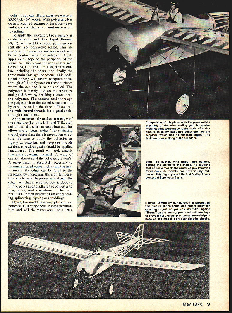
Landing gear: Use 3/32" diameter wire for the main struts, which incidentally go across the fuselage at the top to transfer loads to the basic wing structure and to the wing wires. The 1/32" dia. cross braces are copper wire wrapped prior to soldering. The cross braces take tension loads so that a good joint is mandatory to keep them from pulling apart. Use 1/8" wire for the one piece axle and rubber band it to the gear for shock absorbing and easy removal to install the floats. The landing gear is now attached to the wing at the proper location and the forward upper fuselage is built to fit. Allow for proper wing incidence (2° positive) before gluing everything together. The 1/64" plywood covering is added to the top but the cockpit is not cut out yet. This is done after staining and completing the wing/landing gear assembly. Glue in the brass cabin struts between two bulkheads for support — get it good and solid. This is what you grab when handling this model, very convenient. As indicated on the plans, the nose section is shaped to take the Anzani engine with balsa stubs to hold the cylinders for the seaplane version. The land-plane cowling will cover the cylinder stubs when converted to the land-plane configuration. Finally, close out the bottom of the wing/landing gear assembly by gluing 1/32" plywood to the wing center on the bottom, which now becomes the "floor" for the cockpit. Next, attach the assembly to the fuselage with two nylon screws at each side of the engine, slipping the aft end into the saddle formed by adding the curved 1/64" plywood on the fuselage aft decking.
Flying instructions: Be sure the model is nose heavy. Weight can be removed later as needed to balance the model for normal flight attitude. The model is very docile and with the light wing loading and excess power, you'll enjoy its flight characteristics. Start with a 10" dia., 4" pitch prop to give you additional thrust margin — you don't want speed anyway. The seaplane flies just like the landplane. There is no significant difference in performance. Slide the floats to the position that will give the desired floating attitude and take-off! P.S. Don't try the vertical eights until you gain some confidence in handling the model. Happy splash-down — or bump-down, whatever the case may be!
Transcribed from original scans by AI. Minor OCR errors may remain.

