
Blitz
FUN FLY events are big with our local clubs, and we began to feel the need for a light, nimble plane that would do well in them. That's how the basic design roots of this model began. We named our smooth-flying, talented new sport plane Blitz.
The typical model flown at fun-fly events is a Stik. Now, don't knock the Stik — I've owned a couple myself. The problem is that in Limbo and other low-to-the-ground, quick-response maneuvers this type of aircraft falls short.
What we needed was an airplane with a low wing loading. A lightly loaded plane will turn circles inside a heavier one, allowing those "space-saving" maneuvers that are the key to a fun-fly model's survival. The design should be relatively compact, which is advantageous for Limbo-type events. It should also, when outfitted with a lightweight power plant, attain a creditable range of speed.
To eliminate the need for constant stick maintenance, a stable platform was necessary. Since we wanted the general flight characteristics to be smooth and deliberate, we ruled out a close-coupled design.
I chose a one-piece construction for moderate strength combined with light weight. Transportation is a drawback, but all in all I think it's a small penalty to pay for performance.
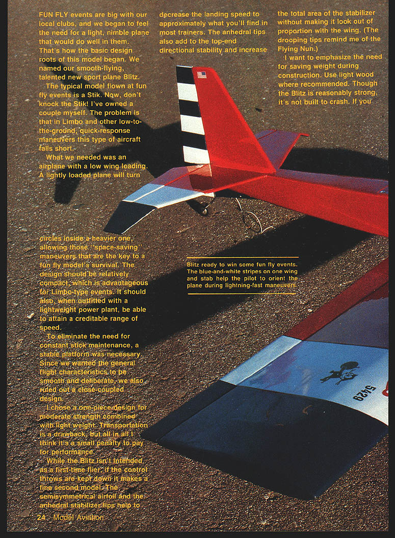
While the Blitz isn't intended as a first-time flier, if the control throws are kept down it makes a fine second model. The semi-symmetrical airfoil and the anhedral stabilizer tips help decrease the landing speed to approximately what you'll find in most trainers. The anhedral tips also add to the top-end directional stability and increase the total area of the stabilizer without making it look out of proportion with the wing. (The drooping tips remind me of the Flying Nun.)
I want to emphasize the need for saving weight during construction. Use light wood where recommended. Though the Blitz is reasonably strong, it's not built to crash. If you follow the plans, you'll end up with a rugged, lightweight model that's smooth and supple in the air.
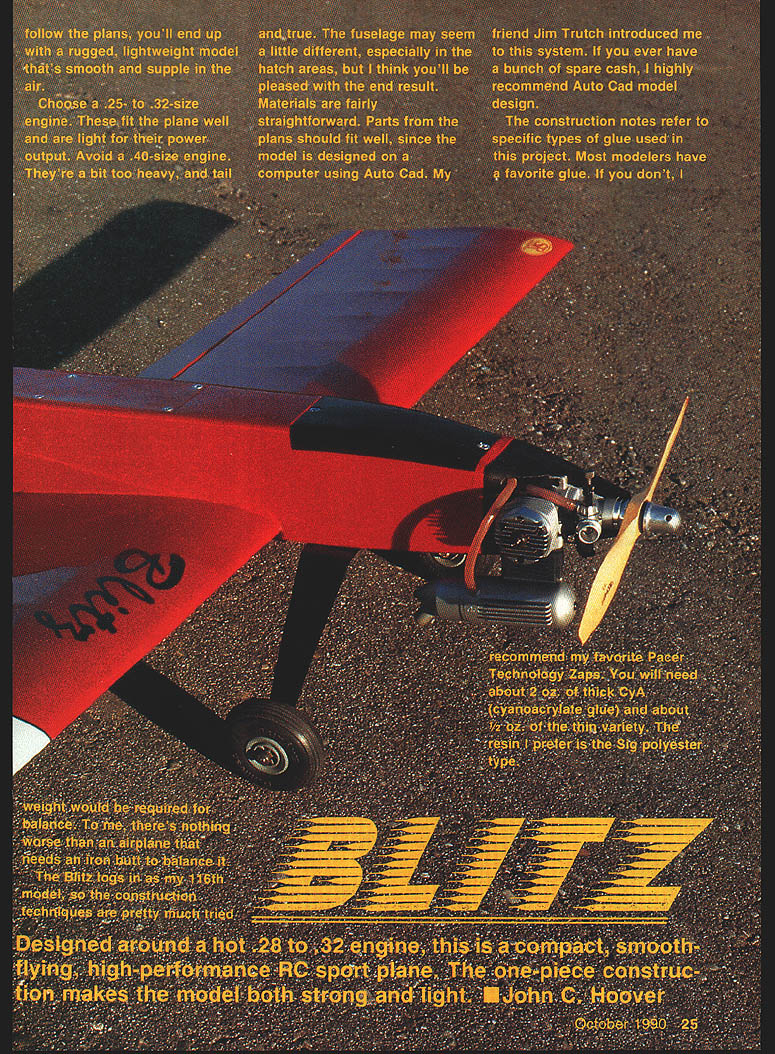
Choose a .25- to .32-size engine; these fit the plane well and are light for their power output. Avoid a .40-size engine — they're a bit too heavy and would require tail weight for balance. To me, there's nothing worse than an airplane that needs an iron bolt to balance it.
The Blitz is my 16th model, so the construction techniques are tried and true. The fuselage may seem a little different, especially in the hatch areas, but I think you'll be pleased with the end result. Parts from the plans should fit well, since the model is designed on a computer using AutoCAD. Materials are fairly straightforward.
The construction notes refer to specific types of glue used in this project. Most modelers have a favorite glue. If you don't, I recommend Pacer Technology Zaps. You will need about 2 oz. of thick CyA (cyanoacrylate) and about 1/2 oz. of thin CyA. The resin I prefer is the Sig polyester type.
Designed around a hot .28 to .32 engine, this compact, smooth-flying, high-performance RC sport plane uses one-piece construction to be both strong and light. — John C. Hoover
Wing
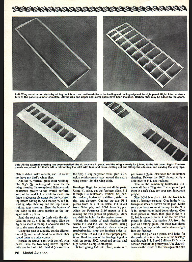
Build the right panel first.
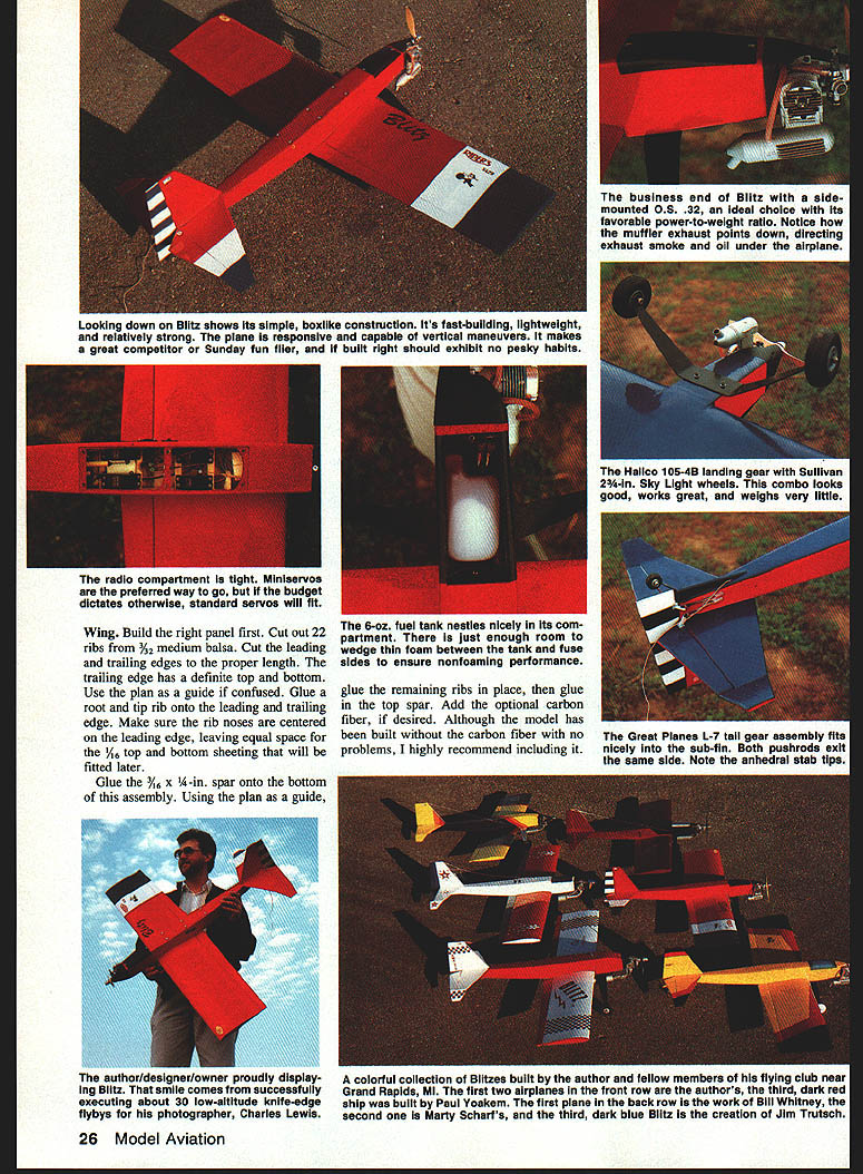
- Cut out 22 ribs from 3/32" medium balsa. Cut the leading and trailing edges to the proper length; note the trailing edge has a definite top and bottom. Use the plan as a guide.
- Glue a root and tip rib onto the leading and trailing edges. Make sure the rib noses are centered on the leading edge, leaving equal space for the 1/16" top and bottom sheeting that will be fitted later.
- Glue the 3/16" x 1/4" spar onto the bottom of this assembly. Using the plan as a guide, glue the remaining ribs in place, then glue in the top spar.
- Add optional carbon fiber to the spar if desired. Although the model has been built without carbon fiber with no problems, I highly recommend including it.
- Add 1/16" vertical-grain shear webbing.
- Use Sig's 1/16" contest-grade balsa wing sheeting for exceptional lightness. File for adequate clearance before adding sheeting.
- Add top 1/16" x 3" leading-edge sheeting and top 1/2" trailing-edge sheeting. Sheet the bottom in the same fashion.
- Sand root and tip flush with ribs. Glue 1/16" x 1/4" rib caps.
- Glue 3/32" balsa sheet wing tips. Carve and sand the tips to match the rib contour.
- Using the plan as a guide, cut the ailerons out of 3/16" medium-to-hard balsa stock and round to a nice contour.
- Repeat the above steps for the left wing panel.
- Glue the two wing halves together for 1" total dihedral (measured at the tips).
- Using polyester resin, glue 1/4" nylon reinforcement tape around the entire wing center.
- Set the wing aside.
Notes:
- Use a file to ensure clearance for all sheeting.
- Aileron linkages: bend and cut two 2-56 rods; Z-bend one end and use a clevis on the other to achieve the control-throw shown on the plan.
Fuselage
Begin by cutting out all parts.
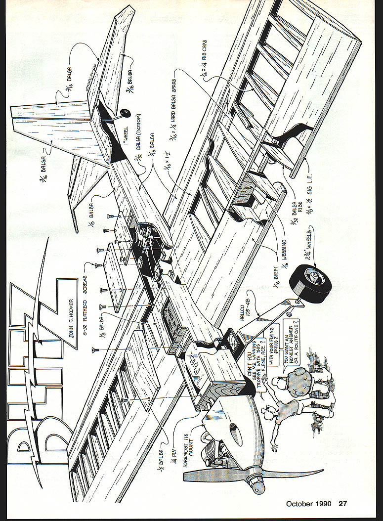
- Using 3/16" balsa, cut the fuselage sides, F-2 through F-4 bulkheads, vertical fin, sub-fin, rudder, horizontal stabilizer, stabilizer tips, and elevator.
- Cut two FS-1 pieces from 3/4" x 4" balsa. Cut F-1 from 1/8" plywood and LG-1 from 1/16" plywood.
- Align the Fourmost #116 engine mount with F-1, making the pieces fit perfectly. Mark and drill holes for the engine mount.
- Mark inside each fuselage half where F-2 through F-4 will be located.
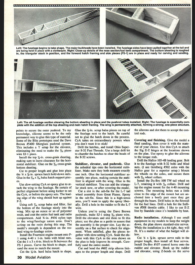
- Using two Acme 3001 spherical elastic clamps (rubber bands), strap the fuselage sides together with F-2 and F-4 in their proper positions. Hold the rear fuselage together with an Acme 3002 wood-and-spring-steel high-tension clamp (clothespin).
- Before gluing F-1 into place, leave 3/16" clearance for the bottom sheeting. Release the 3002 clamp, apply a little glue to F-1, and re-clamp. Glue the remaining bulkheads.
- Glue LG-1 in place. Add the front bottom 3/32" fuselage sheeting. Glue in the 1/8" triangular stock as shown on the plan.
- Leave room at the top for the 1/4" x 3/8" spruce hatch hold-down rails. Glue the hatch-hold-down rails and the 1/16" x 3/16" hatch support pieces.
- Glue the two FS-1 pieces in place. Use section AA from the plan as a fitting guide; fit carefully, they add considerable strength.
- Using the plan, drill holes for pushrod exits at the rear of the fuselage and through F-4. I used Sullivan #503 pushrods on most prototypes. Use clear silicone on the inside of the fuselage at the exits to prevent chafing. The two pushrods run forward and exit the same side of the fuselage.
- Install the wing mount as shown on the plan. Glue F-5 in place and add the top front 3/32" balsa sheeting. Glue in top 1/16" sheeting between F-2 and F-4.
- Install the top 1/8" cross-grain sheeting, leaving clearance for the horizontal stabilizer. Glue on the 3/32" cross-grain bottom sheeting.
Reinforcement and final fitting:
- Glue 3/16" x 1/4" spar onto the bottom assembly. The 6-oz fuel tank nestles nicely in its compartment; wedge thin foam between the tank and fuselage sides to prevent foaming.
- Add optional carbon fiber where desired for additional strength.
- Mix polyester resin and coat the entire fuel tank and radio compartment. Add 3/8" #456 nylon tape to the wing/fuselage union area. Don't scrimp on resin — the model's strength depends on this union.
- Install the Fourmost engine mount onto F-1 using 4-40 x 1" bolts with blind nuts. Cut a 1" x 3" x 6" block to fit between the FS-1 pieces, carve and sand to match the mount.
- Cut and fit the 1/8" hard balsa hatch. Glue 1/8" scrap balsa pieces on top of the fuselage next to the hatch (take care not to glue the hatch down). Drill the hatches and install Ohio Super Star 8-32 Fast Threads. Use a large drill to chamfer the hatch holes to clear the screw heads.
Stabilizer, elevator and pushrods:
- Glue the anhedral tips onto the horizontal stabilizer. Make sure both tips measure exactly the same.
- Glue the horizontal stabilizer assembly into place, aligned with the wing. Glue in the vertical stabilizer.
- Cut a slot in the sub-fin for the Great Planes L-7 tail-wheel assembly. Epoxy the sub-fin in place, using liberal epoxy in this high-stress area. Drill a hole in the rudder to fit the L-7 wire.
- If not using Dave Brown fiberglass pushrod system, make E-J1 from 3/32" piano wire. Drill and slot the elevators to fit this piece using the plan as a guide.
- Lay the aileron assembly on a flat surface to check alignment. Glue with slow-setting CyA when satisfied. Soak the elevator hinge area with thin CyA where shown on the plan to improve strength.
- Cut and bend the #402 strip aileron linkages to proper length and shape. Drill the ailerons and slot to accept control rods.
Covering and finishing:
- Final sand the model. Cover with the material of your choice.
- Use thin CyA to attach Sig E-Z hinges as shown on the plan. Use epoxy to glue ailerons to the torque rods.
- Drill the Hallco 105-4B landing gear and bolt it to the fuselage with 8-32 bolts and blind nuts. I use Goldberg #302 axles with the Hallco gear for a superior setup. Mount wheels and secure with 1/8" wheel collars.
- Install the Du-Bro #100 1" tail wheel on the L-7 assembly, retaining with #2 collars.
- Drill and tap the engine mount for the 4-40 mounting screws. Drill holes in the firewall for fuel lines and a hole for the Sullivan #508 throttle cable. I like to use Standale E-Z Line, bendable by heat.
Radio installation:
- While I use small equipment to keep weight down, the plan shows standard-size servos. It is tight, but standard servos will fit depending on budget.
- Cut 1" x 3/8" spruce servo rails to length and install all four servos.
- Install Du-Bro #107 control horns on rudder and elevator. Hook up rudder and elevator using Z-bends on the servo arms.
- Hook up throttle with the Sullivan #508 flex cable: use a Du-Bro E-Z connector on one end and a Du-Bro #190 ball link on the other.
- Install the Du-Bro #406 6-oz fuel tank, packing 1/4" foam rubber around it to reduce fuel foaming from engine vibration.
- Pack the receiver with 1/2" foam and install in the location shown on the plan. Install the switch between the two groups of servos and exit it through the fuselage side opposite the exhaust.
- The battery should rest between F-4 and the rudder/elevator aft servo rails to retain correct CG. Isolate the battery with foam to reduce vibration.
Final balance:
- Check the model for balance with radio installation complete. Add weight to nose or tail if necessary to achieve the proper center of gravity.
Notes:
- Some Blitz prototypes used the Dave Brown #5400 fiberglass pushrod system, which includes a Y setup for the elevator and eliminates the need for the 3/32" piano wire E-J1 piece.
- For pushrod exits and silicone fastening points, use clear silicone as it seems to be the most durable permanent bond for those materials.
Flying
If balanced properly and given the control throws shown on the plan, Blitz isn't overly touchy. I like to fly smooth maneuvers that look as if they're done on purpose. If you prefer aggressive flying, increase the control throws.
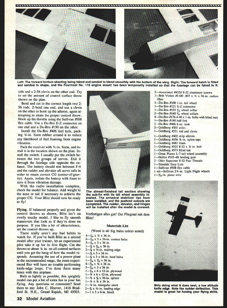
There really aren't any bad habits to watch for. If you've built Blitz as a second model after your trainer, let an experienced pilot take it up for its first flight. Cut the throws to about 1/4" on all control surfaces until you get the hang of how the model responds. With the recommended power plant, the experienced flier will have no trouble performing knife-edge loops — I've done them many times with this airplane.
Built as lightly as possible, this sprightly model can put extra fun in your fun flying.
Any questions or comments? Send them to: John C. Hoover 1416 Bradford St. N.E. Grand Rapids, MI 49503
Verfertigen alles gut! Gut Fliegend mit dem Blitz!
Parts and Hardware (selected)
- 2 — Associated #4328 8-32 aluminum screws
- 1 — Bob Violett #1100 .007 x 1/4 x 36-in. carbon fiber
- 1 — Du-Bro #100 1-in. tail wheel
- 1 — Du-Bro #121 E-Z connector
- 1 — Du-Bro #133 3/32 wheel collar
- 2 — Du-Bro #140 3/32 wheel collars
- 4 — Du-Bro #176 4-40 x 1-in. bolts with blind nuts
- 1 — Du-Bro #190 ball link
- 1 — Du-Bro #406 6-oz. fuel tank
- 2 — Goldberg #302 axles
- 1 — Goldberg #331 rod and clevis
- 1 — Goldberg #402 strip aileron linkage
- 1 — Goldberg #456 3-in. nylon tape
- 1 — Goldberg #482 foam
- 1 — Goldberg #525 8-32 x 3/4-in. bolt
- 1 — Goldberg #573 blind nut
- 1 — Great Planes L-7 tail wheel assembly
- 1 — Hallco #105-4B landing gear
- 2 — Ohio Super Star 8-32 Fast Threads
- 1 — Standale E-Z Line
- 1 — Sullivan #508 flex cable
- 1 — Sullivan 2-in. Sky-Light wheels (pair)
- 1 — 3/32-in. piano wire
Materials List
(Wood is all Sig balsa unless noted)
- 4 — 1/16 x 1/4 x 36 in.
- 6 — 1/16 x 3 x 36 in. contest balsa
- 5 — 1/32 x 3 x 36 in.
- 2 — 1/8 x 3 x 36 in.
- 2 — 1/8 x 1/8 x 36 in. trailing edge
- 1 — 1/8 x 3 x 36 in. hard balsa
- 4 — 1/8 x 1/2 x 36 in.
- 4 — 1/8 x 3 x 36 in.
- 1 — 1/8 x 12-in. plywood (sheet)
- 1 — 1/16 x 1/2-in. plywood
- 1 — 1/8 x 1/8 x 36-in. spruce
- 1 — 1/4 x 1/4 x 36-in. spruce
- 1 — 1/8-in. triangular stock
- 1 — 1/2 x 1/4-in. leading edge
- 1 — 1/16 x 1/8 x 36-in. block
Notes and recommendations:
- Use light wood where specified and save weight whenever possible.
- Recommended glue: thick and thin CyA; recommended resin: Sig polyester type.
- Recommended engine: .25–.32 (hot .28–.32 for best performance). Avoid .40-size engines to prevent excessive tail weight.
Transcribed from original scans by AI. Minor OCR errors may remain.

