
Blondie
Chris Sackett
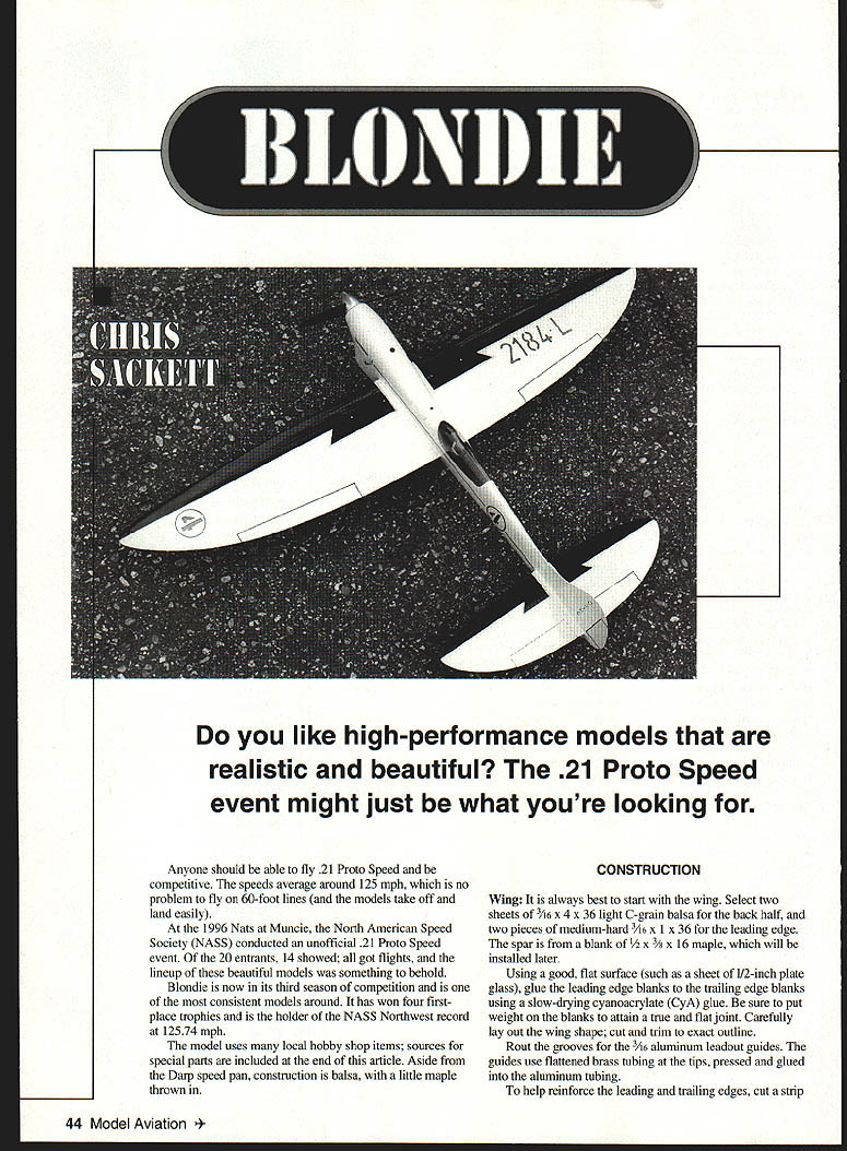
Do you like high-performance models that are realistic and beautiful? The .21 Proto Speed event might just be what you're looking for.
Anyone should be able to fly .21 Proto Speed and be competitive. Speeds average around 125 mph, which is no problem to fly on 60-foot lines (and the models take off and land easily).
At the 1996 Nats at Muncie, the North American Speed Society (NASS) conducted an unofficial .21 Proto Speed event. Of the 20 entrants, 14 showed; all got flights, and the lineup of these beautiful models was something to behold.
Blondie is now in its third season of competition and is one of the most consistent models around. It has won four first-place trophies and is the holder of the NASS Northwest record at 125.74 mph.
The model uses many local hobby shop items; sources for special parts are included at the end of this article. Aside from the Darp speed pan, construction is balsa, with a little maple thrown in.
Construction
Wing
- Start with the wing. Select two sheets of 3/16" x 4" x 36" light C‑grain balsa for the back half and two pieces of medium‑hard 3/16" x 1" x 36" for the leading edge. The spar is from a blank of 1/2" x 3/8" x 16" maple, installed later.
- Using a good flat surface (such as a sheet of 1/2" plate glass), glue the leading edge blanks to the trailing edge blanks with a slow‑drying cyanoacrylate (CyA). Put weight on the blanks to attain a true, flat joint. Lay out the wing shape and cut to exact outline.
- Rout grooves for the 3/16" aluminum leadout guides. Tip guides use flattened brass tubing pressed and glued into the aluminum tubing.
- Reinforce the leading and trailing edges by fitting a strip of 1/32" plywood into the leading‑edge outline and a 1/32" deep trailing‑edge plywood insert. The trailing insert strengthens the sharp edge and provides a reference line for carving the airfoil.
- Assemble leadout guides, tip weight, and plywood inserts on the plate‑glass base to ensure a warp‑free wing. Glue guides and tip weight with slow‑drying CyA, place 1/32" plywood reinforcement pieces, position the top half, place a second piece of plate glass on top, and add weight. Apply firm pressure and wait about 1/2 hour for the CyA to set.
- Carve and sand a symmetrical airfoil. If you want to taper the wing, do so while keeping a clean shape.
- Spar installation: cut the spar per the plans and recess the bellcrank area. Taper the spar close to the wing thickness and cut the wing to accept it. Because the bellcrank has permanently installed hookup buttons, install the bellcrank now: place it in position, drill a 1/8" music‑wire pin, and glue the spar cap with strong epoxy. Set aside to dry. Epoxy the spar into the wing, finalize carving and sanding to shape.
- Sand the wing to final finish with #320 paper. Cover with 1‑ounce fiberglass cloth using Z‑Poxy, sand smooth when dry, and apply another coat of Z‑Poxy Stabilizer.
Stabilizer and Elevator
- Make the stabilizer from two sheets of 3/32" light C‑grain balsa with a 1/32" plywood piece inserted between the sheets. Carve and sand the stab to a sharp, symmetrical airfoil and cover with 1‑ounce fiberglass cloth.
- Cut out the elevator and install the elevator horn. The outer axle control horn is formed from .047" music wire as shown on the plans. Solder a piece of brass pushrod bushing to the wire loop and drill the horn to accept the .047" pushrod.
- Wax the control‑horn axle and cut pockets in the stab to accept it. Mix epoxy with finely chopped fiberglass cloth to a puttylike consistency and lay the elevator assembly in place. Spread the glue mixture over the axles and cover completely to give a perfect hinge assembly with no play.
Fuselage — Pan, Crutch and Blocks
- Use a Darp AP 21 magnesium speed pan. Hog out the pan to accept your engine and drill/tap for the 4‑40 x 1/2" engine tie‑down bolts. Locate positions for the four pan tie‑down bolts and tap these 4‑40 also; use as much depth as the pan will allow for solid threads (about 1/4"–3/16" is normal). Finish‑shape the pan to match the spinner and thin as desired.
- Lighten the pan internally: use a rotary tool to hog the pan out to around .120" thick from the front to the back of the engine and about .090" from the rear of the engine to the back of the pan. A pan thinned like this should weigh about 40–45 grams.
- Make a crutch from two strips of 1/4" square hardwood and a blank of medium‑hard 3/8" x 2" balsa sheet. Draw the fuselage shape to match your pan and the plan. Thin the hardwood strips to 1/8" behind the rear of the pan so they will bend easily to form the fuselage contour. Taper and trim toward the rear.
- Glue the hardwood strips to the 3/8" balsa using slow‑drying CyA. Use small blocks of balsa between the strips to space and align correctly.
- Do all this over a flat surface (plate glass). The wing and stab are built off the crutch; 0° wing and stab alignment is important.
- Mount the engine in the pan and place in position on the crutch. Use a hole saw to cut out the engine area in the bottom fuselage block. The bottom block is 1‑3/4" x 1‑3/4" x 20" medium balsa. Lightly tack‑glue the bottom block in place; do the same for the turtledeck and rudder while shaping.
- Make the rudder from 1/16" C‑grain balsa with sides from 1/16" C‑grain balsa. Rough‑shape the fuselage to the drawing, insert the rudder and blend in.
- Break the fuselage apart and hollow out the balsa blocks to around 3/8"–3/16" wall thickness. Give special care to the minipipe exit on the lower block — the pipe should be angled slightly downward to clear the wing (this will vary by engine). Do not remove more wood internally around the lower cowl than necessary.
Assembly and Covering
- Notch the crutch to accept the wing and stab. Flip the crutch and glue the pan in place on the crutch with a generous bead of epoxy along the pan flange; clamp or weight while the epoxy cures. Install the 4‑40 tie‑down bolts and check alignment.
- Sand the assembled fuselage smooth and prepare for covering. Cover the fuselage with 1/2‑ounce fiberglass cloth using Z‑Poxy as used on the wing. Sand smooth when dry and apply a final coat of Z‑Poxy Stabilizer.
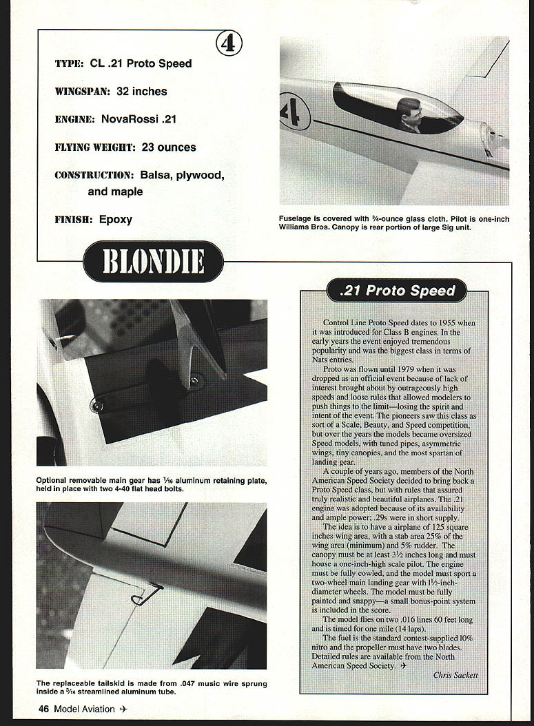
- Fit the optional removable main gear with a .032" aluminum retaining plate held in place by two 4‑40 flat‑head bolts. The replaceable tail skid is made from .047" music wire sprung inside a 3/16" streamlined aluminum tube.
Spar, Bellcrank and Controls
- Install the bellcrank and permanently affix hookup buttons as noted earlier. Install the .055" pushrod (with a guide on it which will be glued to the bulkhead later).
- For extended model life, give internal surfaces a couple of coats of thinned clear epoxy paint — especially around the bellcrank area of the wing and all through the back of the fuselage.
- Attach top and bottom fuselage blocks. The rear pan bulkhead is from 1/4" plywood and serves as an alignment key for the pan. Shape the bulkhead to match the back of the pan with no slop.
Pan Tie‑Down Bolt Installation
- It is best to install pan tie‑down bolts early. To locate positions, install 4‑40 x 1/4" screws in the pan, protruding about 3/32". Lower the pan onto the crutch to leave marks for the tie‑down bolts, mark carefully, and drill (ideally in a drill press for alignment).
- Drill the holes oversize to accept 5/32" tie‑down sleeves. The sleeves are 5/32" brass tubing with 4‑40 washers soldered on top to prevent bolts from pulling through the wood and ensure a solid attachment.
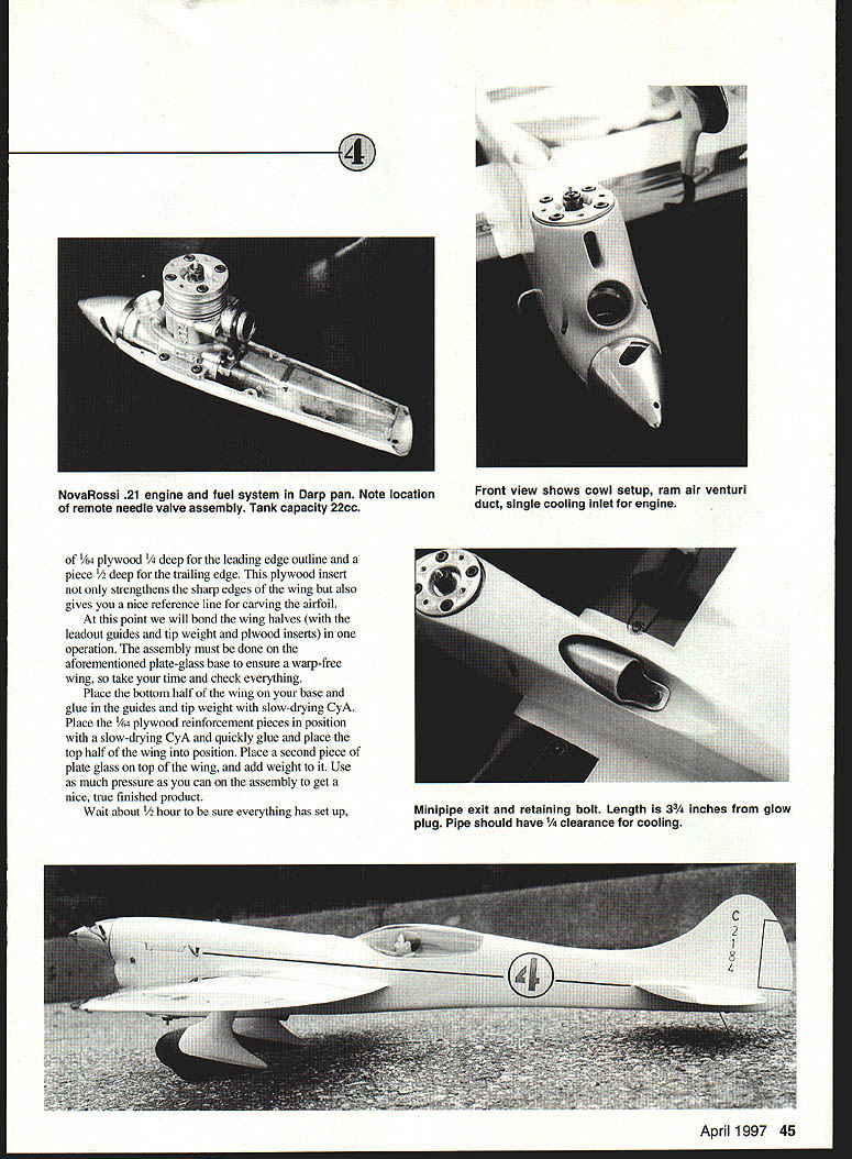
Engine Cowling and Cooling
- Finish shaping the engine cowling area. Use a ram duct for the venturi and a single cooling duct for the engine. The minipipe should exit the bottom cowling at as shallow an angle as possible (typically around 8°). This may require modifying the engine exhaust stub.
- Allow at least 1/4" clearance around the duct for adequate cooling. Retain the minipipe with a single 4‑40 x 1/2" bolt at the tip of the exhaust, using a 4‑40 threaded insert secured with CyA.
- The finished fuselage may be finished as desired; some builders use heavier cloth in the final areas, but the standard covering for Blondie is 1/2‑ounce fiberglass with Z‑Poxy.
Cockpit and Canopy
- Build a cockpit floor at the base of the crutch from 1/16" hard balsa (grain spanwise); install a balsa bulkhead for an instrument panel and detail as desired.
- Select a one‑inch Williams Bros. scale racing pilot, paint and install with a pin and epoxy. The canopy can be formed from the rear portion of a larger Sig unit; recess about 1/32" around the cockpit, seal with 1/4‑ounce fiberglass cloth, mask the canopy outline and blend to the fuselage with epoxy putty for a clean hidden canopy line.
Landing Gear
- The original model uses a removable gear system but the gear can be mounted permanently if preferred. Bend 3/32" wire as shown on the plans and install 1‑1/2" racing wheels (Glenn Lee wheels are recommended).
- Notch the spar to accept the gear and drill a vertical hole through the spar for the tang. Make gear retaining plates from 1/16" hard aluminum and drill/tap the spar for 4‑40 bolts. Run thin CyA into the threads for long‑lasting engagement.
- Wheel pants: two pieces of medium‑hard 1/8" balsa glued to the 3/32" wire, bottoms from two pieces of 3/16" medium‑hard balsa. Seal wheel cavities with clear epoxy for long life, blend and shape pants, and cover with 2‑ounce fiberglass cloth and Z‑Poxy.
Tank and Fuel System
- Tank: a 22 cc unit located in the pan area. Use 3/32" tubing for the pickup and pressure line. The pickup tube is soldered to the outside of the tank and an .055" hole is drilled through after the line is soldered in place to help meter fuel for a steady run.
- Place the pressure tube as shown on the plan. The fill line is 1/8" tubing drilled for a 4‑40 bolt as a cap. Filling is achieved using a 1/32" tube from the filler.
- Attach the tank to the pan with clear silicone glue and position it as close as possible to the wing. To prevent flooding during startup, use a small ball check valve between the engine and the pressure line. Ensure the tank sits straight and true and that the pickup is at the farthest point of the tank's position.
Final Assembly and Finish
- With the airframe sanded and fair, finish‑coat and paint as desired. Balance the model as shown on the plans and check control throws. Mount the spinner and the propeller recommended for your engine and trim for straight running on the ground first.
- Because appearance points are part of scoring, a good paint scheme and finish are important. Sand the entire model with 400‑grit wet‑or‑dry paper; fill nicks/dings with Model Magic filler.
- Use a good epoxy paint finish such as K&B Super Poxy. Spray a coat of K&B primer and sand most of it off with 320 or 400 wet‑or‑dry paper. Spray color coats (two light coats), then sand with 600, followed by 1000, 2000 and polish.
- Spray two coats of K&B clear epoxy paint and let harden for at least a month. Hand sand with 600 and 1000 grit, then 2000 and polish with Brasso for a deep gloss. For an even deeper finish, wax the model with a modern automotive wax designed for clearcoat finishes.
Engine and Propellers
- Modern .21 engines (especially NovaRossi) are competitive out of the box. The author installed a remote needle valve assembly for ease of operation (available from Performance Model Parts).
- A propeller around 6.75 x 5.2 is a good starting point. Try Pylon Racing props or specialty makers such as Al Kelly, Mike Hazel (Z Z Prop) or APC.
Flying
- Make up lines just over 60 feet in length (centerline of handle grip to centerline). Use .016" wire lines available from Morris Speed Gear.
- Fill the tank slowly through the filler, put a couple drops of fuel into the venturi and turn the engine over by hand a couple of times. Hook up the battery and start with the spinner in the starter. Once the needle valve is set the engine should start instantly.
- Have your pit man release the model fairly quickly. The tank is good for about 16–17 laps — enough for timing and not much more. Take off with the model neutral or with a hint of up for fast, smooth takeoffs.
- For flingoff power and acceleration, trim for a slightly nose‑down attitude on the initial run and use full power to accelerate on the lines. Once at speed, establish a clean, level attitude and fine‑tune down‑thrust and right‑thrust as necessary. Make small adjustments and check the airplane on successive flights.
- Blondie flies predictably and is forgiving in the smaller speed classes. Land the model fairly "hot" while giving slight down control as soon as the wheels touch.
Specifications
- Type: CL .21 Proto Speed
- Wingspan: 32 inches
- Engine: NovaRossi .21 (recommended)
- Flying weight: 23 ounces
- Construction: Balsa, plywood, maple
- Finish: Epoxy
Rules, Contact and Membership
- For full rules on .21 Proto Speed, contact the North American Speed Society (NASS). Rules are available for $2; full membership is $24 (US and Canada), $29 elsewhere.
- If you have questions or comments on this event, contact:
Chris Sackett Box 82294 Burnaby, B.C. V5C 5P7 Canada (604) 299‑4500
Specialty Equipment Suppliers
- NovaRossi Engines
Rossi Sales of America (Bill McGraw) 1325 Carol Drive Memphis, TN 38116 (901) 396‑7485
- Darp AP 21 Speed Pans
Darp (Nick Arpino) 301 Woodacres Road East Patchogue, NY 11772 (516) 286‑8144
- Spinners
George Brown III Custom Engines 2442 W. Park Ave. Chandler, AZ 85224
- Wheels
Glenn Lee 819 W. Mandrake Dr. Batavia, IL 60510
- Bellcranks and Lines
Ned Morris 9044 Rushmore Blvd. S Indianapolis, IN 46234
- Propellers
Al Kelly 4616 Harvey Western Springs, IL 60558
Z Z Prop (Mike Hazel) 1073 Windermere Drive NW Salem, OR 97304
- Needle Valve Assemblies
Performance Model Parts (Glen Dye) 12177 South 1565 E Draper, UT 84020‑9644 (801) 571‑7017
Transcribed from original scans by AI. Minor OCR errors may remain.

