
The Blue Birds
"The most exciting of all model air show acts, and a magnificent technical achievement, is the designer's formation model consisting of four jets locked together and powered by a single OS Max 10."
- Ken Willard
Introduction / Background
No, they're not the Blue Angels (which fly the A4D) and they're not the Thunderbirds (which fly the T-38). I called my hybrid team the "Blue Thunder Angel Birds," but shortened it to the "Blue Birds." With Blue Angels color markings, people invariably yell, "Hey, look! The Blue Angels!" when they fly overhead.
Everyone agrees that this "formation plane" is one of the most unusual R/C designs in recent memory, ranking with the Flying Doghouse, Flatiron, and Lawn Mower as a show stopper. The obvious questions are: How did the idea come about, and how did I get it to balance and fly?
Inspiration
- The original idea goes back to the 1930s Marines' Top Hats team that tied their planes together with a ribbon and performed aerobatics while still connected.
- I experimented with joining small ten-cent gliders at the wingtips.
- In 1968 I built a scale model of the Phoenix-Warren Skycar (a rhomboid/diamond wing). After seeing the Blue Angels flying in diamond formation, the similarity suggested tying four planes together in a diamond and balancing it like a rhomboid wing. The Blue Birds are the result.
Development and Testing
Hand-launched glider tests
- Built a hand-launched glider version first.
- Tried adjustable ailerons on outboard wings of the wingmen and used the tail's stab for elevator — ailerons worked, stab didn't.
- Replaced stab movement with simultaneous up/down movement of the rear plane's ailerons so they acted as the elevator for the whole formation — this worked but required a lot of up-elevator for level flight.
- Realized that the rhomboid wing is a reflex airfoil. By aligning the rear plane slightly nose-down when the others were level, the stability problem was solved.
Center of gravity (C.G.)
- C.G. should be roughly the same as the Skycar.
- Tests showed C.G. location is not extremely critical: too far forward reduces elevator effectiveness; too far back makes the assembly wallow.
- After tests, a location was chosen that gave good straight flight and elevator action; the location can vary about 1/2 inch.
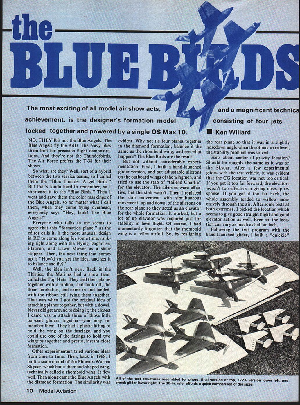
Quickie powered version
- Built a quick powered version to test the concept under engine power.
- Construct four virtually identical aircraft, then modify one as the lead plane (dowel attachment and power) and the rear plane to carry the elevators controlling the whole formation.
1/6A and 1/4A versions
- 1/6A: Cut and shaped ACE foam wings, used scrap foam fuselages, installed radio; the rearward plane's wing installed upside down to help provide a reflex airfoil — it worked.
- 1/4A (no throttle): Flew full power or glide. Initial flight crashed due to insufficient elevator/aileron authority in the glide. After increasing control throws, the model was responsive under power, but in slow flight the elevators were ineffective because the wing was full of holes (airflow through surfaces at high angle of attack).
- Solved landing issue with flying technique: when engine quit, push down into a ~30° dive and at low altitude pull up to flare using excess speed. This required room and reliable engine control to avoid a situation with insufficient altitude for the dive.
Public Demonstration
First public demo was at the Pioneers of World War II Scramble at the Hill Country Air Museum. The ship was kept under a sheet on a station wagon, then driven to a secluded launch spot about 75 yards south of spectators. Using a Cannon Supermini engine installation, the display drew a tremendous reaction — roar, wonder, applause. The routine included a formation loop, a wide-open barrel roll, a split-S, a high-speed pass, return and landing. The crowd response was overwhelming.
The Max 10 Version
- After proving the concept, I designed a larger version around the OS Max 10. The Max 10 offers an excellent idle-to-full speed range, making landings easier with a bit of throttle: establish a sink rate on final and apply some up elevator; the slipstream hits the elevators and the plane flares.
- I used the Cannon Supermini during development because of availability and suitability, but various super-mini systems (Kraft, Ace, Futaba, Litco, etc.) can be used.
Construction
Materials and general notes
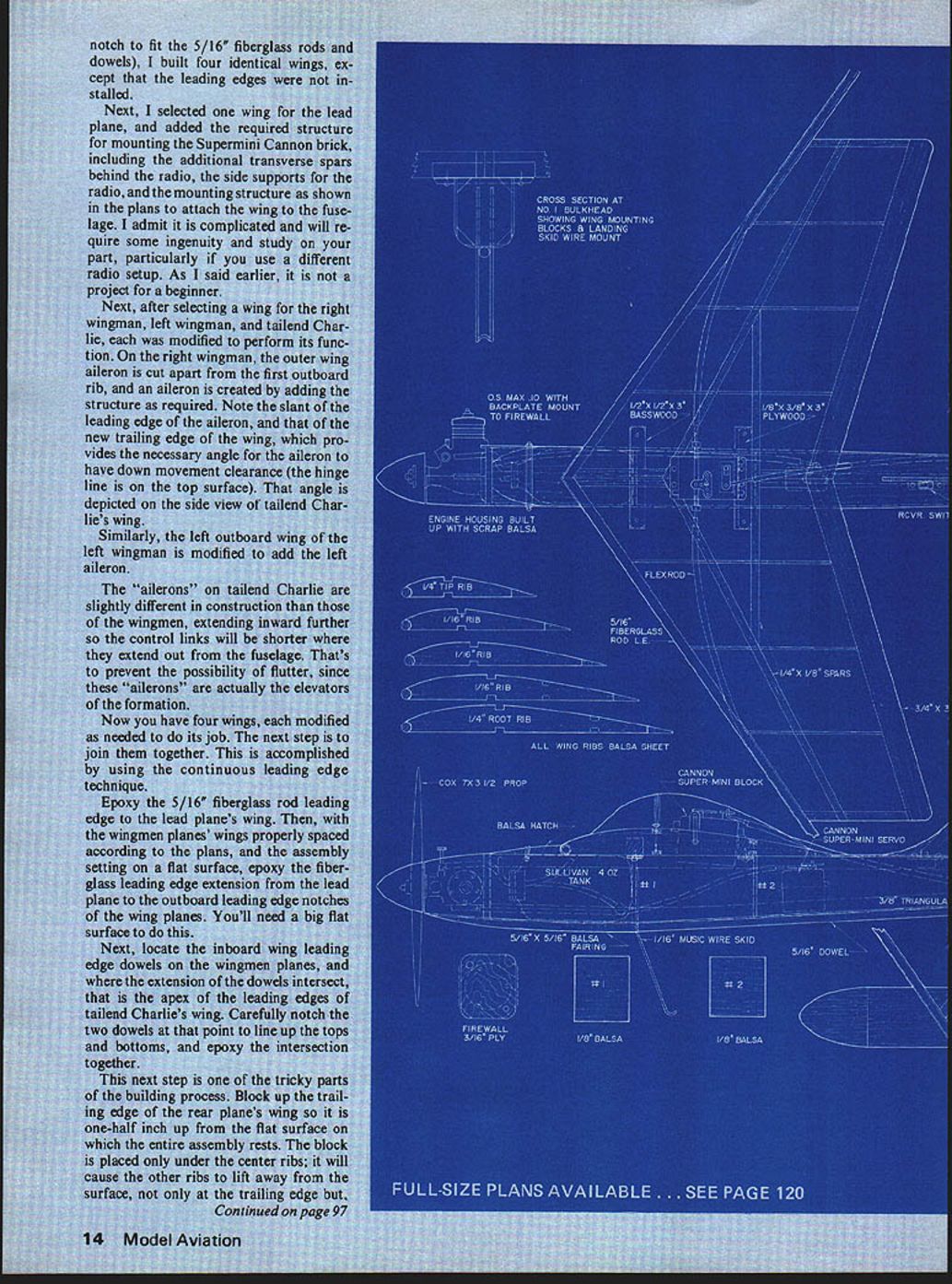
- Fuselage construction uses triangular longerons with sides slotted to receive bulkheads; add top and bottom sheeting, install nose blocks and glue in place.
- No rear bulkhead is needed—leave the opening at the back for finishing and decorating. Paint the back opening brilliant orange to simulate afterburners.
- Round corners where triangular stock allows; leave corners square under the wing and stab for better seating surfaces.
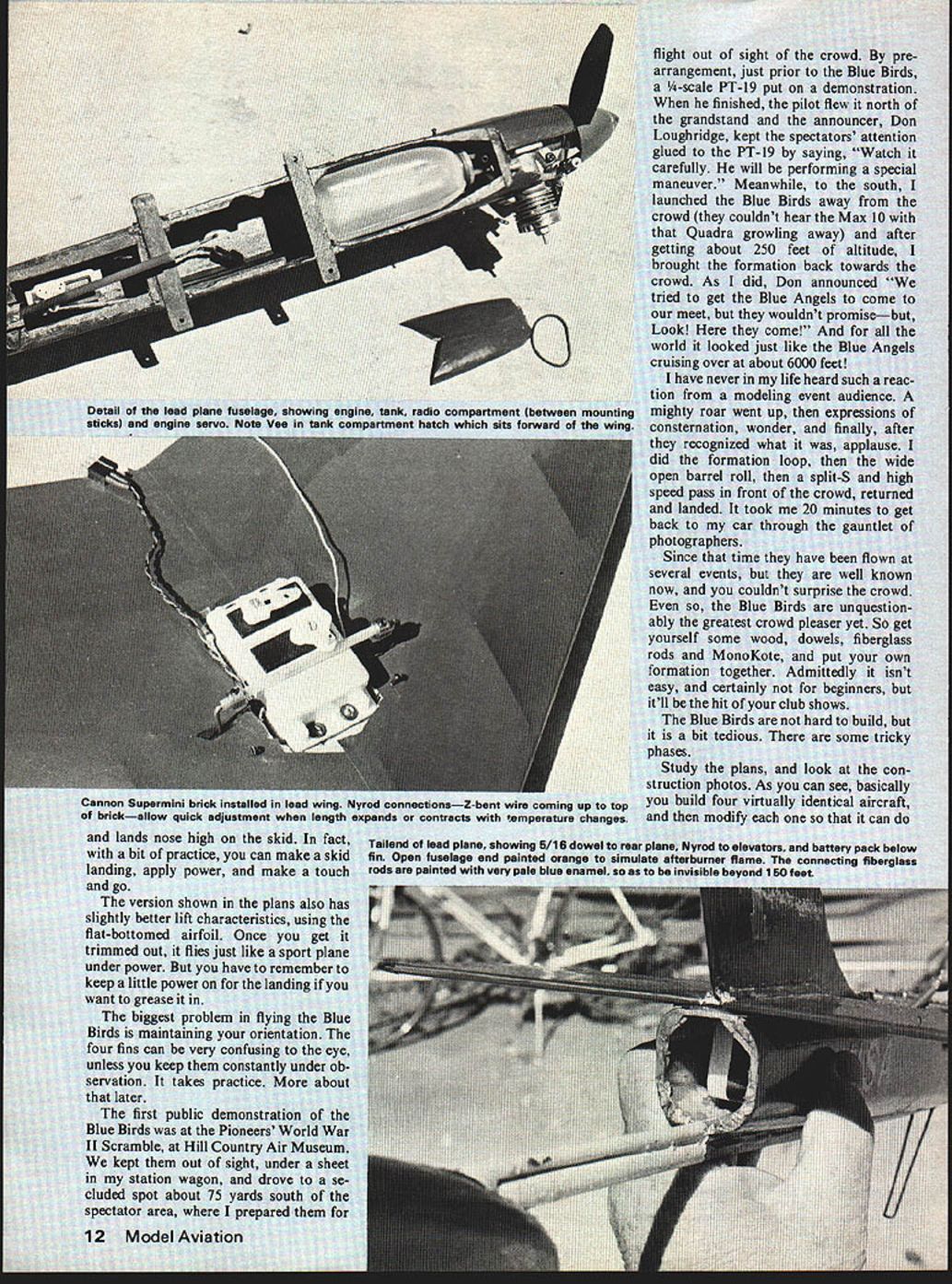
- The lead plane fuselage differs slightly: it has a 3/16" plywood firewall up front, bulkheads #1 and #2 spaced differently to accommodate fuel tank and radio, and no top sheeting forward of the trailing edge to allow access to tank/engine/servo compartments.
Battery and ballast
- Install battery pack during construction sequence: leave top sheeting off, cut away triangular stock, insert pack, then sheet over.
- The pack is permanently installed to help move weight aft; Blue Birds tend to be nose-heavy. I carried two ounces of ballast attached to the end of the dowel protruding from the tail of the rear fuselage.
- A four-ounce tank is well ahead of the CG, so the model becomes slightly tail-heavy as the tank empties; I usually fly only about two ounces of fuel to avoid large trim changes.
Fuselages
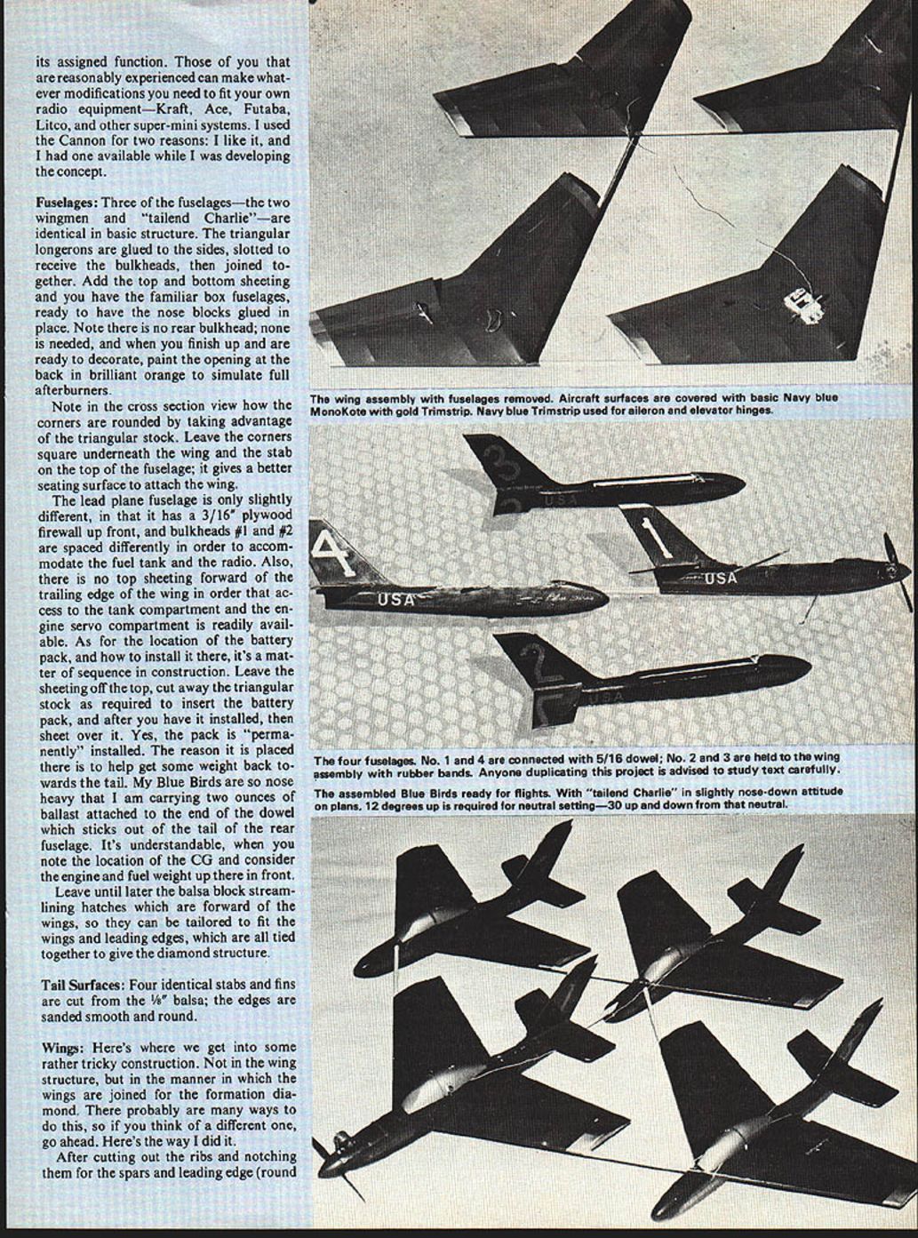
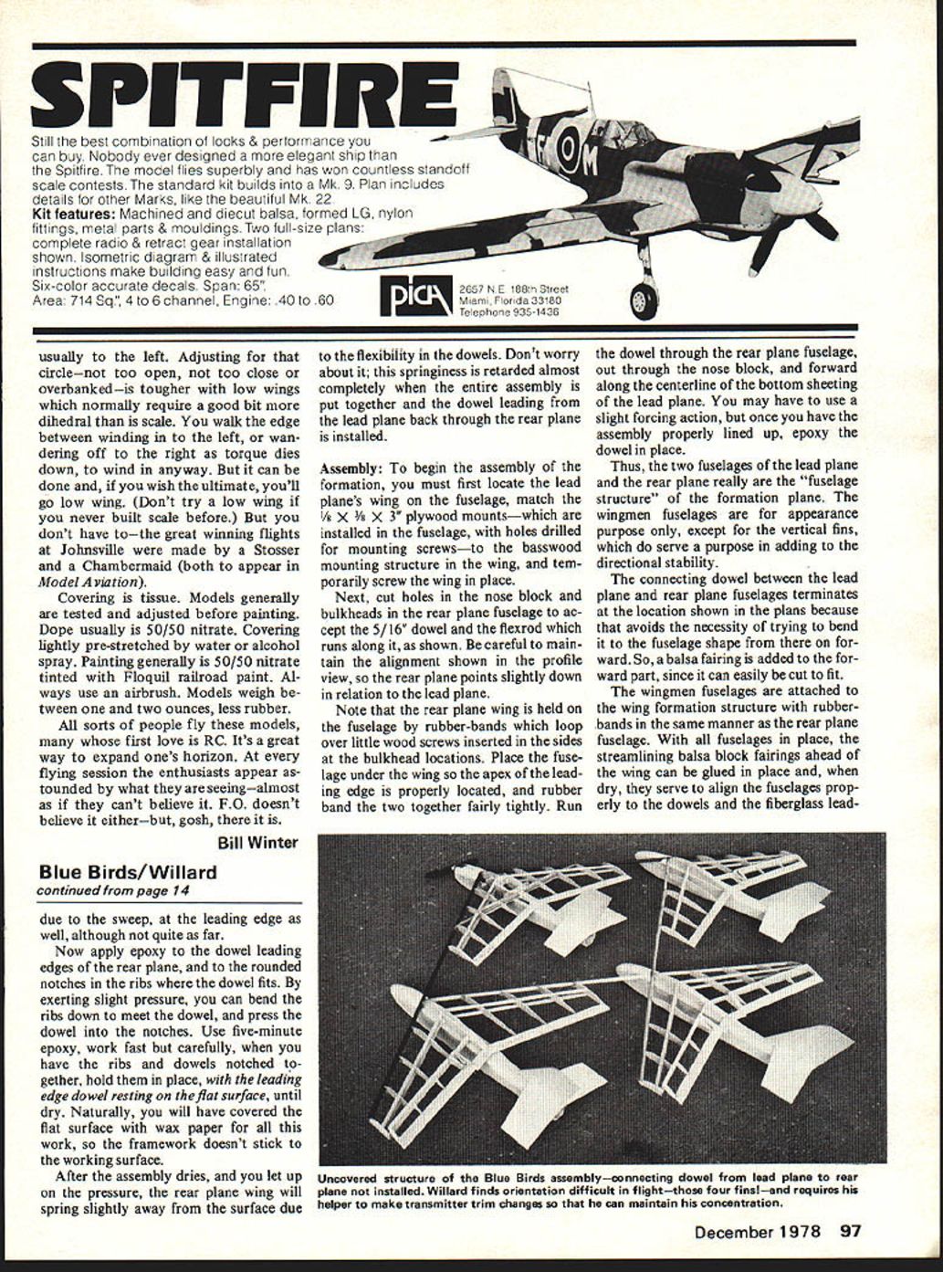
- Three fuselages (two wingmen and tail-end "Charlie") are identical in basic structure.
- The lead fuselage includes the plywood firewall and radio/tank spacing differences noted above.
- Wingmen fuselages are mostly for appearance; vertical fins add directional stability.
- Attach wingmen and rear fuselages to the wing formation with rubber-bands looping over small wood screws at bulkhead locations. Streamlining balsa block fairings ahead of the wing align fuselages to dowels and the fiberglass leading edge.
Tail surfaces
- Four identical stabs and fins cut from 1/8" balsa; sand edges smooth and round.
Wings and the diamond jointing technique
- Cut ribs and notch them for spars and leading edge (round notch to fit 5/16" fiberglass rods and dowels).
- Build four identical wings initially, leaving leading edges off.
- Modify one wing (lead plane) for Supermini/Cannon brick, radio mounts, and attachment structure.
- Modify right wingman outer outboard aileron; similarly modify left wingman left outboard aileron.
- Tailend Charlie's ailerons are constructed differently: they extend inward further so control links are shorter (these ailerons act as elevators for the formation).
- Join wings using the continuous leading-edge technique:
- Epoxy a 5/16" fiberglass rod leading edge to the lead plane's wing.
- Epoxy extensions to wingmen outboard leading edge notches while assembly rests on a big flat surface covered with wax paper.
- Locate inboard wing leading edge dowels of wingmen; where their extensions intersect is the apex for tailend Charlie's leading edges. Notch and epoxy the intersection.
- Block up the trailing edge of the rear plane wing 1/2" above the flat surface (only under center ribs). Apply epoxy to rear plane leading-edge dowels and ribs, press and hold until dry so ribs conform to the dowel. Use five-minute epoxy and work quickly.
- After drying, the rear wing will spring slightly; final rigidity is achieved when the continuous dowel from lead to rear is installed.
- After assembly dries, round corners, remove wing, sand, and apply light filler for a good finish on the leading edge. Add little block fairings behind leading-edge extensions from the wing apex.
Assembly of fuselages to wing structure
- Mount the lead plane's wing to its fuselage using 1/8 x 3/8 x 3/8 plywood mounts installed in the fuselage and basswood mounting structure in the wing; temporarily screw the wing in place.
- Cut holes in rear fuselage nose block and bulkheads for the 5/16" dowel and the flexrod that runs along it. Maintain the correct profile alignment so the rear plane points slightly down relative to the lead plane.
- Run the dowel through the rear fuselage, out through the nose block, and forward along the centerline of the lead plane bottom sheeting. Epoxy the dowel in place once aligned.
- The lead and rear fuselages become the primary fuselage structure; wingmen fuselages are largely cosmetic but support vertical fins.
- Add balsa fairings forward of the wing and glue when dry to align fuselages properly.
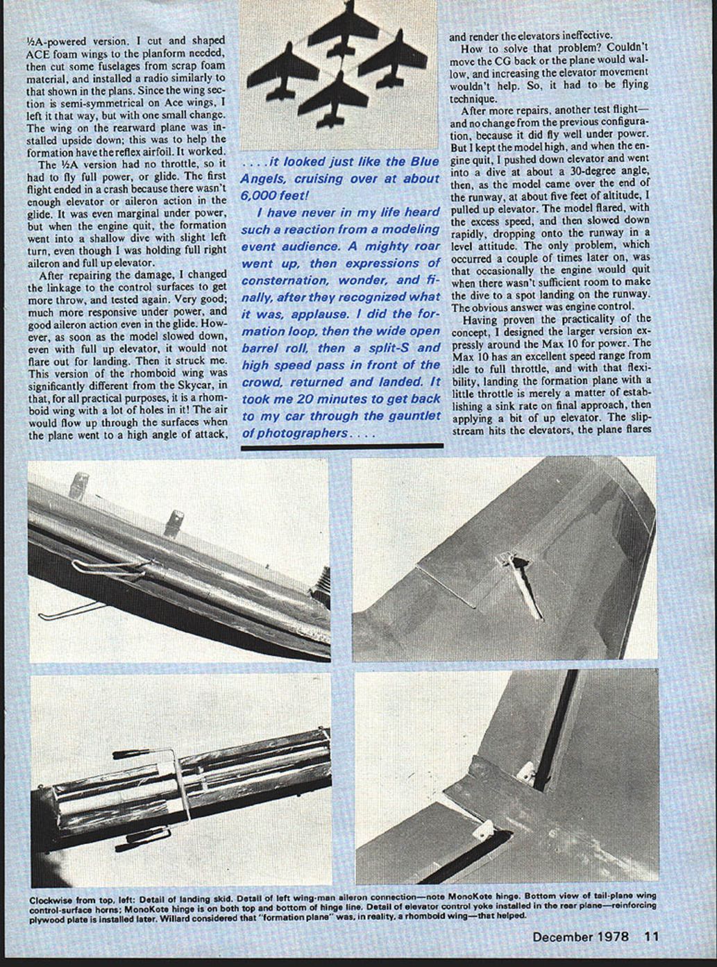
Landing gear and skids
- Attach tail surfaces, epoxy wire landing gear skid in place, install rear nylon skid.
- Install nylon skids on bottom of wingmen fuselages at the back ends to prevent abrasion when landing on asphalt.
Engine Installation
- Engine mounting is a builder's choice. Prefer short mounts keeping the engine close to the firewall for balance and appearance; backplate mounting is simple and effective for the Max 10.
- Engine servo mounted on servo tape on the bottom; add a couple drops of Hot Stuff adhesive between tape and bottom sheeting as a precaution against pulling loose.
- Tailor the flexible engine control rod to fit the engine arm and servo. Build up the forward fuselage fairing to house the engine, provide access to mounting bolts and control clevis, and fair into the spinner (example: 1-1/2" spinner on a Cox 7-3/2 prop).
Receiver and Control Rods
- For future builds I would install a small receiver in the lead fuselage compartment (just aft of the tank) and run long leads to servos mounted individually in the wings just ahead of the surfaces to be moved. This would avoid temperature-induced flexrod expansion/contraction issues. Check with your radio manufacturer about adding chokes if servo leads exceed ~15 inches.
- My setup: flexrods are inserted into the fiberglass leading edges, exit just outboard of wingmen fuselages, and curve around to the aileron horns. A small balsa brace between spars holds the curve.
- Aileron flexrod attachments:
- Drill a small hole in the side of a short inner nyrod, insert a wire with a 90° bend that engages the servo control.
- Insert a Z-bend wire into the aileron nyrod; use a wheel collar to position and secure the Z-bend inside the short nyrod. Apply a drop of Hot Stuff to permanently attach the Z-bend end inside the aileron nyrod.
- Wheel collar method allows easy assembly/disassembly and adjustment for temperature changes.
- Elevator flexrod routing:
- Route nyrod carefully through fuselage past battery pack and epoxy it to the top of the connecting dowel back to bulkhead #2 in the rear fuselage.
- At the rear, use a wire bent 90° inserted through a short inner nyrod; where that exits the rear fuselage, use short Quiklink wire rods with clevises cut to length and bent 90° so ~1/2" of wire sits inside the nyrod.
- Stiffen the T-joint by epoxying a small piece of 1/16" plywood (prevents elevator flutter at high speed).
Covering and Finish
- Cover with Super MonoKote or similar.
- Trim: gold Trimstrip over Navy blue; Navy blue Trimstrip used to make aileron and elevator hinges.
- Paint connecting fiberglass rods and dowels a very pale blue (mix light blue and white enamel) so they blend with the sky at distance (almost invisible beyond ~150 ft).
Flying
Trimming and control throws
- With CG as shown on plans, tailend Charlie is slightly nose-down; neutral elevator setting was about 12° up. Total throw should be about 30° up and 30° down from that neutral. Ailerons should have at least 30° of throw.
- On first flight, have an experienced associate hand-launch the Blue Birds while you stand ready to correct any tendency to dive or climb steeply. Have the associate return to adjust trims while you fly if necessary — do not attempt to hand-launch and trim alone.
- Maintain constant visual orientation: the four fins can confuse the eye; keep them under observation to avoid disorientation, which only lessens when they are virtually overhead.
- Practice dead-stick procedures: glide angle and elevator response are critical if engine flame-out occurs. Dead-stick landings are difficult because the formation wing is essentially full of holes.
Engine idle and fuel management
- The Max 10's throttle flexibility makes landing much easier; keep a little power on during landing for elevator authority.
- The four-ounce tank is forward of the CG; flight becomes tail-heavy as fuel is used. Avoid flying the tank dry; fly about two ounces of fuel to minimize trim changes.
- Be prepared to adjust trim for temperature-induced flexrod expansion/contraction before each flight.
Tips and cautions
- Expect to persevere through confusing or less-obvious construction stages.
- Use reliable engine control to avoid insufficient-altitude emergencies when using dive-to-flare landing technique.
- Consider placing servos in wings and running long leads from a fuselage receiver for temperature stability, but check manufacturer advice about chokes for long servo leads.
- Use small nylon skids to protect wingmen fuselages on rough landings.
Final Notes
- After trimming, the Blue Birds fly like a sport plane under power and are a spectacular showpiece. Keep a little throttle on final, watch for orientation confusion, and practice glides for engine-out landings.
- You'll likely curse some construction details, but persevere — you'll be the hit of the show with your Blue Birds.
Transcribed from original scans by AI. Minor OCR errors may remain.

