
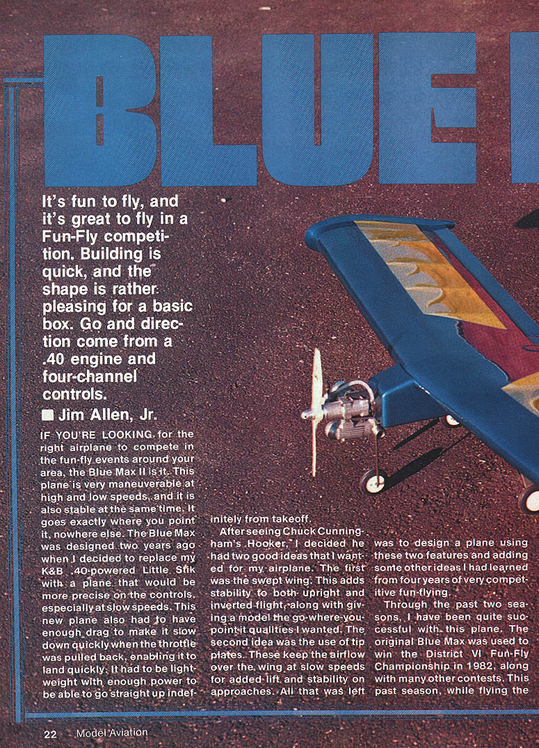
Blue Max II
It's fun to fly, and it's great to fly in a Fun-Fly competition. Building is quick, and the shape is rather pleasing for a basic box. Power and directional control come from a .40 engine and four-channel controls.
Jim Allen, Jr.
If you're looking for the right airplane to compete in the fun-fly events around your area, the Blue Max II is it. This plane is very maneuverable at high and low speeds, and it is also stable at the same time. It goes exactly where you point it, nowhere else. The Blue Max was designed two years ago when I decided to replace my K&B .40-powered Little Stik with a plane that would be more precise on the controls, especially at slow speeds. This new plane also had to have enough drag to make it slow down quickly when the throttle was pulled back, enabling it to land quickly. It had to be lightweight with enough power to be able to go straight up indefinitely from takeoff.
After seeing Chuck Cunningham's Hooker, I decided he had two good ideas that I wanted for my airplane. The first was the swept wing. This adds stability to both upright and inverted flight, along with giving a model the go-where-you-point-it qualities I wanted. The second idea was the use of tip plates. These keep the airflow over the wing at slow speeds for added lift and stability on approaches. All that was left was to design a plane using these two features and adding some other ideas I had learned from four years of very competitive fun-flying.
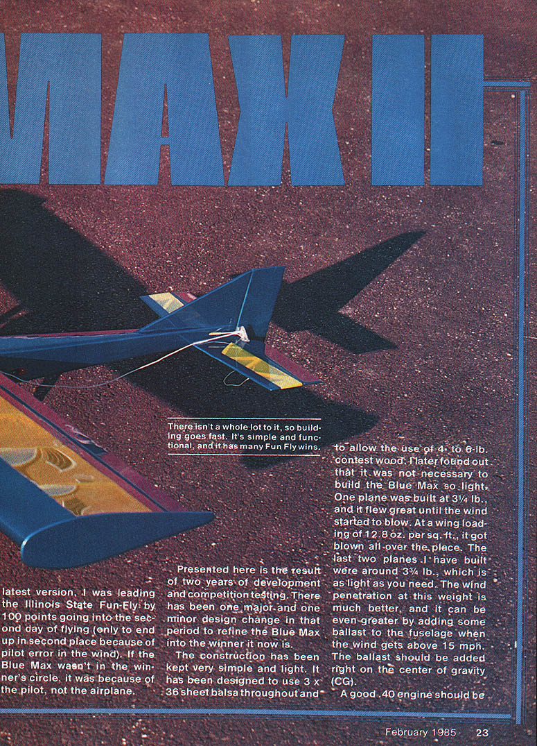
Through the past two seasons, I have been quite successful with this plane. The original Blue Max was used to win the District VI Fun-Fly Championship in 1982, along with many other contests. This past season, while flying the latest version, I was leading the Illinois State Fun-Fly by 100 points going into the second day of flying (only to end up in second place because of pilot error in the wind). If the Blue Max wasn't in the winner's circle, it was because of the pilot, not the airplane.
Presented here is the result of two years of development and competition testing. There has been one major and one minor design change in that period to refine the Blue Max into the winner it now is.
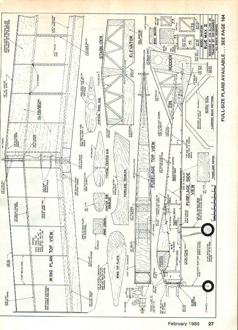
The construction has been kept very simple and light. It has been designed to use 3/32" sheet balsa throughout and to allow the use of 4- to 6-lb. contest wood. I later found out that it was not necessary to build the Blue Max so light. One plane was built at 3-1/2 lb., and it flew great until the wind started to blow. At a wing loading of 12.8 oz. per sq. ft., it got blown all over the place. The last two planes I have built were around 3-3/4 lb., which is as light as you need. The wind penetration at this weight is much better, and it can be even greater by adding some ballast to the fuselage when the wind gets above 15 mph. The ballast should be added right on the center of gravity (CG).
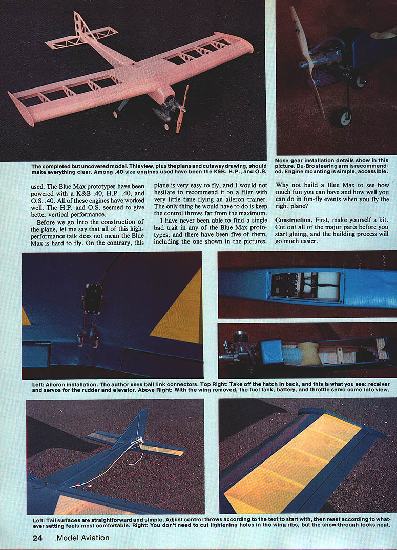
The Blue Max prototypes have been powered with several 40-size engines. Among those used are:
- K&B .40
- H.P. .40
- O.S. .40
All of these engines have worked well. The H.P. and O.S. seemed to give better vertical performance.
Before we go into the construction of the plane, let me say that all of this high-performance talk does not mean the Blue Max is hard to fly. On the contrary, this plane is very easy to fly, and I would not hesitate to recommend it to a flier with very little time on an aileron trainer. The only thing he would have to do is to keep the control throws far from the maximum.
I have never been able to find a single bad trait in any of the Blue Max prototypes, and there have been five of them, including the one shown in the pictures.
Why not build a Blue Max to see how much fun you can have and how well you can do in fun-fly events when you fly the right plane?
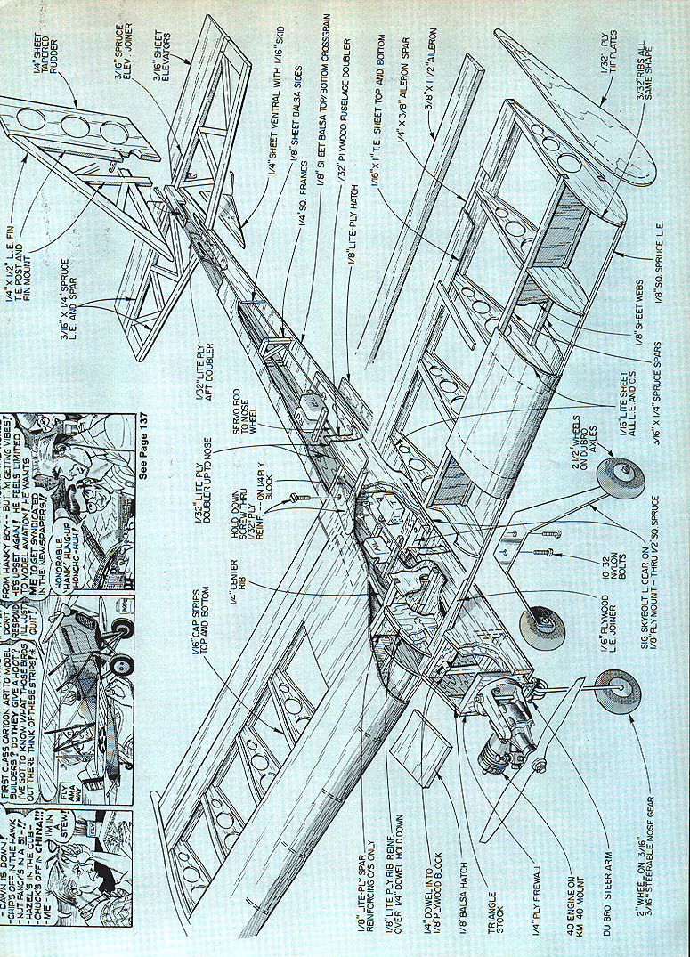
Construction
First, make yourself a kit. Cut out all of the major parts before you start gluing, and the building process will go much easier.
Tail surfaces are straightforward and simple. Adjust control throws according to the text; start with the lower-than-maximum settings and increase only if the feel is comfortable. You don't need to cut lightening holes in the wing ribs unless you want the look under a transparent covering. All remaining parts should be cut to match the plans.
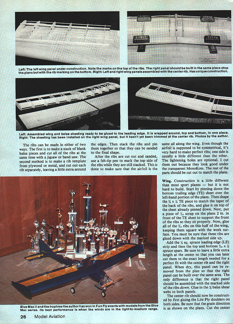
Ribs can be made either of two ways. First, make a stack of blank balsa pieces and cut the ribs at the same time on a jigsaw or band saw. The second method is to make a rib template from plywood or metal and cut each rib separately, leaving a little extra around the edges so they can be sanded to final shape. After the ribs are cut and sanded, use a felt-tip pen to mark the top side of the ribs while they are still stacked; this helps ensure the airfoil is the same along the wing. Though the airfoil is supposed to be symmetrical, it's very hard to make perfect ribs, so the two sides are usually a little different. Lightening holes are optional.
Wing Construction
Start by pinning down the bottom trailing-edge (TE) sheet over the left-hand portion of the plans. Shape the TE piece to match the taper of the rear ribs and glue the back ribs in place. Glue the top sheet after the ribs are pinned down. Next, add a scrap piece in front of the TE sheet to support the front of the ribs so they sit properly. Now glue in the ribs for half the wing, keeping everything square to the work surface and making sure the ribs are glued down with the marked side up.
Add the spruce leading edge strip and the top and bottom spruce spars, leaving a little extra length at the center so they can be cut to the exact length later for a perfect fit with the center rib. When the left panel is dry, remove the panel from the plan. The right panel can be built over the same area; the only difference is the right panel should be assembled with the marked side of the ribs down. Glue on the balsa sheeting and finish the wing per the plans.
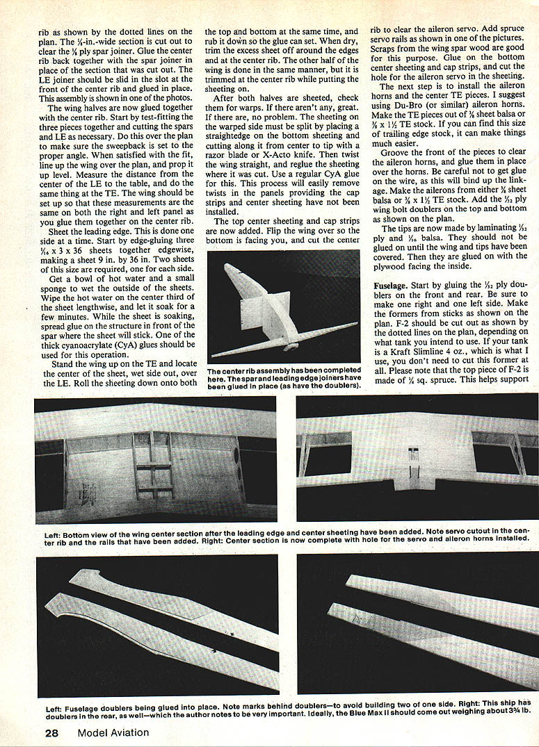
The center rib should now be constructed by first gluing the Lite Ply doublers on both sides. Be sure that the grain direction is as shown on the plans. The center rib is cut as shown by the dotted lines on the plan. The 1/4-in. wide section is cut out to clear the 1/8 ply spar joiner. Glue the center rib back together with the spar joiner in place of the section that was cut out. The LE joiner should be slid in the slot at the front of the center rib and glued in place. This assembly is shown in one of the photos.
The wing halves are now glued together with the center rib. Start by test-fitting the three pieces together and cutting the spars and LE as necessary. Do this over the plan to make sure the wing incidence is set to the proper angle. When satisfied with the fit, line up the wing over the plan, and prop it up level. Measure the distance from the center of the LE to the table, and do the same thing at the TE. The wing should be set up so that these measurements are the same on both the right and left panel as you glue them together on the center rib.
Sheet the leading edge. This is done one side at a time. Start by edge-gluing three 1/16 x 3 x 36 sheets together edgewise, making a sheet 9 in. by 36 in. Two sheets of this size are required, one for each side.
Get a bowl of hot water and a small sponge to wet the outside of the sheets. Wipe the hot water on the center third of the sheet lengthwise, and let it soak for a few minutes. While the sheet is soaking, spread glue on the structure in front of the spar where the sheet will stick. One of the thick cyanoacrylate (CyA) glues should be used for this operation.
Stand the wing up on the TE and locate the center of the sheet, wet side out, over the LE. Roll the sheeting down onto both the top and bottom at the same time, and rub it down so the glue can set. When dry, trim the excess sheet off around the edges and at the center rib. The other half of the wing is done in the same manner, but it is trimmed at the center rib while putting the sheeting on.
After both halves are sheeted, check them for warps. If there aren't any, great. If there are, no problem. The sheeting on a warped side may be split by placing a straightedge on the bottom sheeting and cutting along it from center to tip with a razor blade or X-Acto knife. Then twist the wing straight, and reglue the sheeting where it was cut. Use a regular CyA glue for this. This process will easily remove twists in the panels providing the cap strips and center sheeting have not been installed.
The top center sheeting and cap strips are now added. Flip the wing over so the bottom is facing you, and cut the center rib to clear the aileron servo. Add spruce servo rails as shown in one of the pictures. Scraps from the wing spar wood are good for this purpose. Glue on the bottom center sheeting and cap strips, and cut the hole for the aileron servo in the sheeting. The next step is to install the aileron horns and the center TE pieces. I suggest using Du-Bro (or similar) aileron horns. Make the TE pieces out of 1/16 sheet balsa or 1/8 x 1/2 TE stock. If you can find this size of trailing edge stock, it can make things much easier.
Groove the front of the pieces to clear the aileron horns, and glue them in place over the horns. Be careful not to get glue on the wire, as this will bind up the linkage. Make the ailerons from either 1/16 sheet balsa or 1/8 x 1/2 TE stock. Add the 1/8 ply wing bolt doublers from the top and bottom as shown on the plan.
The tips are now made by laminating 1/8 ply and 1/16 balsa. They should not be glued on until the wing and tips have been covered. Then they are glued on with the plywood facing the inside.
Fuselage
Start by gluing the 1/8 ply doublers on the front and rear. Be sure to make one right and one left side. Make the formers from sticks as shown on the plan. F-2 should be cut out as shown by the dotted lines on the plan, depending on what tank you intend to use. If your tank is a Kraft Slimline 4 oz., which is what I use, you don't need to cut out this former at all. Please note that the top piece of F-2 is made of 1/8 sq. spruce. This helps support the loads of the wing mount.
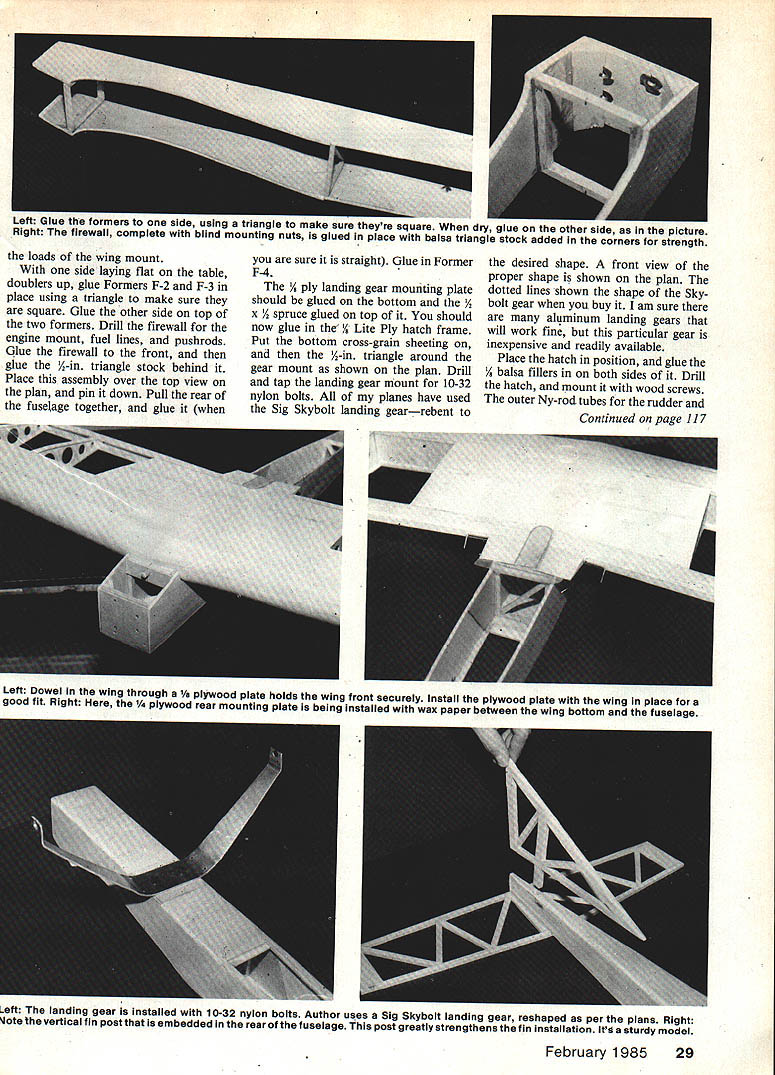
With one side laying flat on the table, doublers up, glue Formers F-2 and F-3 in place using a triangle to make sure they are square. Glue the other side on top of the two formers. Drill the firewall for the engine mount, fuel lines, and pushrods. Glue the firewall to the front, and then glue the 1/2-in. triangle stock behind it. Place this assembly over the top of the wing on the plan, and pin it down. Pull the rear of the fuselage together, and glue it (when you are sure it is straight). Glue in Former F-4.
The 1/2-ply landing gear mounting plate should be glued on the bottom and the 1/2 x 1/2 spruce glued on top of it. You should now glue in the 1/8 Lite Ply hatch frame. Put the bottom cross-grain sheeting on, and then the 1/2-in. triangle around the gear mount as shown on the plan. Drill and tap the landing gear mount for 10-32 nylon bolts. All of my planes have used the Sig Skybolt landing gear—rebent to the desired shape. A front view of the proper shape is shown on the plan. The dotted lines show the shape of the Skybolt gear when you buy it. I am sure there are many aluminum landing gears that will work fine, but this particular gear is inexpensive and readily available.
Place the hatch in position, and glue the 1/8 balsa fillers in on both sides of it. Drill the hatch, and mount it with wood screws. The outer Ny-rod tubes for the rudder and elevator should be glued in now. Remember, they only have to come up to the hatch area. Make sure they exit the fuselage sides far enough forward so they do not interfere with the rudder post.
Mount the completed wing to the fuselage. First, open the hole where the dowel will go into the center rib and test-fit the dowel. Do not glue it in. Line up the wing on the fuselage; make sure it is centered and square. With the dowel temporarily in place, slide the 1/2-ply wing mount into place on the dowel, and glue it to the front of F-2. Do not move the wing until the glue is dry. The triangle stock can now be added in front of the wing mount.
With the wing still in place, slide a piece of wax paper between the wing TE and the fuselage where the rear mounting plate is to be glued. Use 5-minute epoxy to glue the 1/4-ply plate in place under the wing. Hold it firmly against the bottom of the wing until the glue has set. Remove the wax paper and double check to make sure the wing is straight. Now, drill down through the wing (where the doublers are) and through the mounting plate. Drill out the hole in the plate for a 10-32 bolt. Add the 1/4 balsa top block to the fuselage in front of the wing and the top, rear 1/8 balsa cross-grain sheeting.
Tail surfaces. Build them over the plan as shown. Be sure to use spruce for the leading and trailing edges of the stab. Cut the hole in the top fuselage sheeting to clear the 1/4 x 1/4 rudder post. Do not leave this part out, as it adds a great deal of strength to the installed fin.
Glue the stab to the bottom of the fuselage, making sure it is properly aligned. Glue the fin and the sub-fin into place. Sand the rudder to a tapered shape (and I suggest that you cut out the lightening holes as shown on the plan). The tail of the Blue Max is quite long, so everything in the rear should be kept as light as possible.
Finishing touches. Final-sand everything, and cover the plane with one of the iron-on covering materials. I strongly recommend MonoKote for its strength and ease of application. I also make my hinges out of the same material and have never had a failure.
Install the engine mount and nose gear. The nose gear goes up through the mount with the steering arm just below the mount and a wheel collar (either inside or on top of the mount) to hold the gear in place. If you know someone with a coil bender, I strongly recommend that you use a 1/32-in. wire nose gear. These heavy-duty struts save a lot of props. In case a bender is not available, a 5/32-in. gear will work just fine. Install the tank, and run the fuel lines through the center of the mount. Mount the engine with 6-32 bolts on the mount far enough to leave room for the fuel lines to come through.
Mount the rudder and elevator servos in the back under the hatch. Make sure they are far enough rearward to allow the receiver to be placed just ahead of them. Use a cable pushrod to go from the rudder servo to the nose gear. The cable housing should be firmly glued down over its entire length to prevent any flexing. The throttle servo is mounted in an aileron servo tray just ahead of F-3, flat on the floor. A cable pushrod should be used for the throttle, also. Battery location in the fuselage depends on where it is needed for balancing purposes. This is normally under the wing right behind the tank. The aileron servo is mounted in the wing on the rails installed earlier. Use sheet metal screws for attaching the servo in the conventional manner.
The CG should fall somewhere between the limits shown on the plan. The best way to check the CG is to place your fingers under the spars on both sides of the wing, and slide your fingers in and out equally on both sides. The limits for this method are shown on the wing plan.
Desired control throws for starting:
- Ailerons: 1/2 in. up and down
- Elevator: 1/2 in. up and down
- Rudder: 1/4 in. left and right
These throws will give an easy-to-fly (but responsive) airplane. After some test flights, the throws can be adjusted to whatever the flier feels comfortable with.
On the first flight, open the throttle while holding slight back pressure on the elevator. It will lift off the ground in about 30 to 40 feet. Let it climb out so you can get the feel of the way it flies. From here on, it's up to you.
The Blue Max is a very versatile airplane.
Blue Max/Allen
Continued from page 117
It is especially tough in events that require tight maneuvering and quick landings. I feel the Blue Max is superior in almost every event it has ever been flown in—until it gets windy. When the wind starts to blow, the heavier .60-size planes have a definite advantage. A scaled-up .60 version of this plane might be a future project for me to cure this problem.
I am sure you will not be disappointed with the Blue Max II. Anyone who has ever flown it has fallen in love with its flying characteristics. Have fun.
Transcribed from original scans by AI. Minor OCR errors may remain.

