
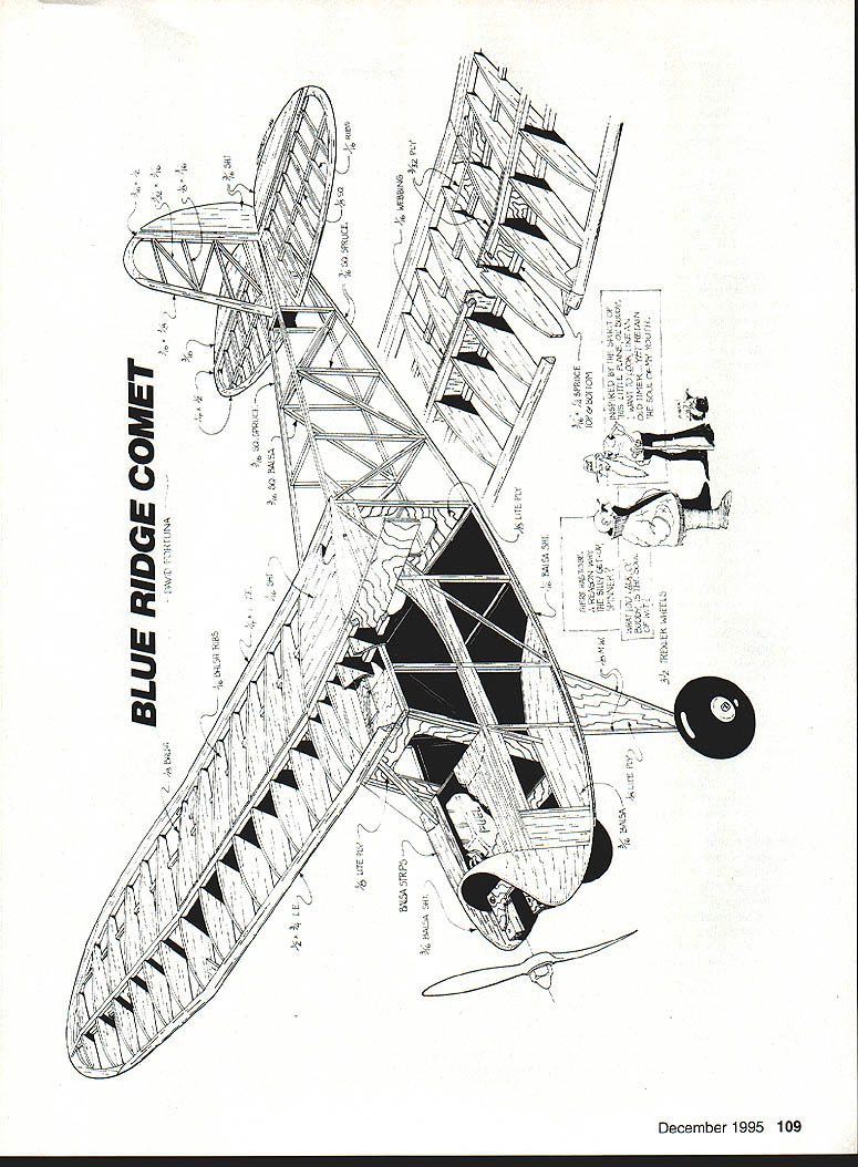
Blue Ridge Comet
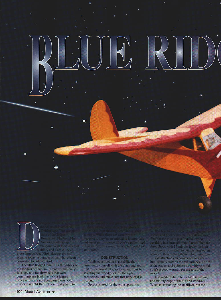
Designed in the 1930s, the Blue Ridge Comet is a throwback to the models of that era. It features the boxy fuselage and flat windshields that were commonplace back then. One feature not found on those "Old-Timers" is split flaps; these help lower landing speed and improve approach control. With their inherent stability and classic lines, these famous free-flight designs remain popular today, and a number have been converted to radio control.
Description
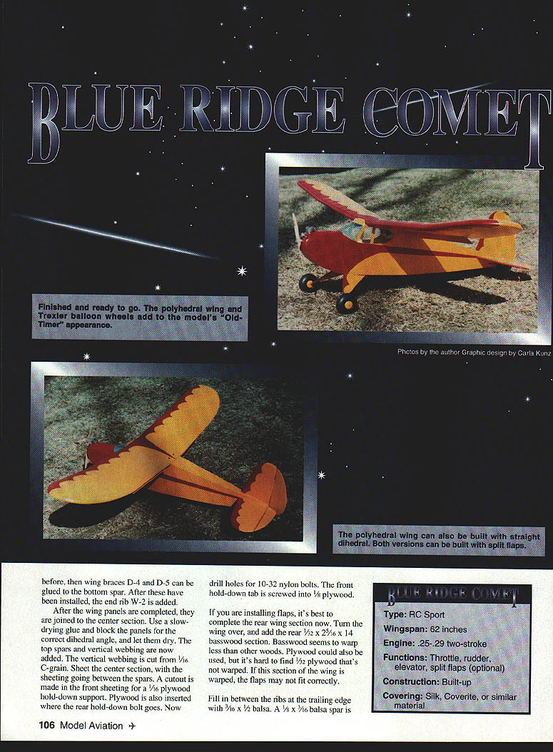
- Type: RC Sport
- Wingspan: 62 inches
- Engine: .25–.29 two-stroke (a .40 four-stroke also works well)
- Functions: Throttle, rudder, elevator, split flaps (optional)
- Construction: Built-up
- Covering: Silk, Coverite, or similar material (strong covering recommended for the open framework)
The Comet is inherently stable and flies slowly and smoothly. Split flaps increase stability and allow slower flight and more manageable landings.
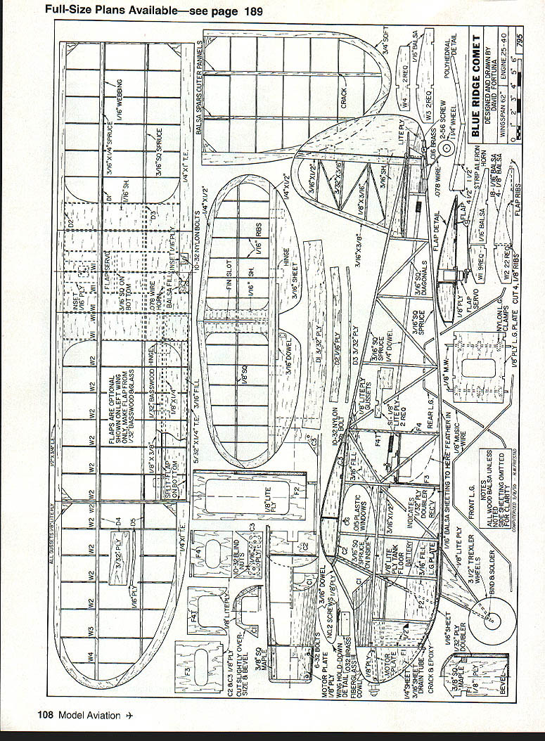
Construction
While construction is not difficult, familiarize yourself with the plans and text first to understand how it all goes together. Select straight, unwarped wood of the appropriate hardness.
Materials summary
- Spruce: wing spars and sheeting in some areas
- Medium-hard balsa: leading and trailing edges of fin and stabilizer
- Medium-soft balsa: rudder and elevators
- Lite ply: bottom of rudder, plywood hold-down support, gear mounts
- Basswood (1/32" or 1/8" as noted) or 1/32" plywood: rear wing section where flaps attach
- 3/4-oz glass cloth and epoxy (or fiberglass resin): flap reinforcement
- Music wire: .078" for flap horn wires; 1/8" music wire for landing-gear legs
- Maple: engine mounts
- Nylon clamps, blind nuts, 10-32 nylon bolts, 6-32 bolts
Tail surfaces
- Start on the tail surfaces—easiest and quickest assembly.
- Use medium-hard balsa for leading and trailing edges of fin and stabilizer.
- Pin parts in place and glue carefully to maintain alignment.
- When stabilizer is completed, undercut the center ribs and leave a slot in top sheeting for the fin.
- Cut rudder and elevators from medium-soft balsa; pin elevators with a 3/16" dowel.
- Use lite ply on the bottom of the rudder where the rudder horn and tail-wheel wire mount.
- Fin is 3/16" balsa. Part of the fin fits into the stab slot; the remainder mounts on top.
- Carefully cut hinge slots and shape leading edges and ribs with a sanding block.
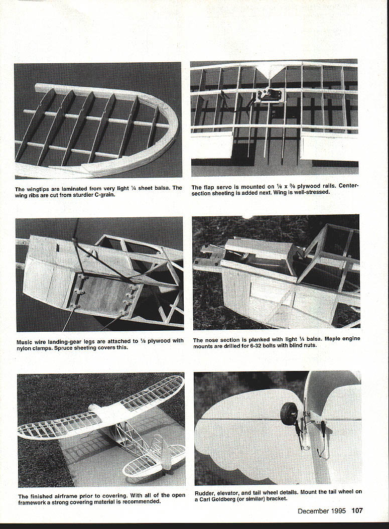
- Mount the tail wheel on a Carl Goldberg–style bracket.
Wing construction
- Spruce is used for the wing spars.
- Wing braces D-4 and D-5 are glued to the bottom spar.
- Install end rib W-2, then add W-1.
- Build ailerons and flaps in the wing panels.
- After completing wing panels, join the center section using slow-drying glue. Block the panels at the correct dihedral angle and let dry.
- Add top spars and vertical webbing (cut from 1/16" C-grain sheet). Sheet the center section with sheeting running between the spars.
- Make a cutout in the front sheeting for a plywood hold-down support. Insert plywood where the rear hold-down bolt goes. Drill holes for the 10-32 nylon bolts. Screw the front hold-down tab to 1/8" plywood.
Outer panels are constructed like inner panels: pin down leading-edge spars and trailing edge, check alignment with the inner panel before gluing ribs. When joining panels to the center section, lay the inner panel flat and raise the outer panel to the correct dihedral, then add rib W-2 and the tip spar. The tip spar is cracked at rib W-3 to bend down at the tip; add gussets where indicated.
Fill between ribs at the trailing edge with appropriate balsa spar stock (examples given in plans: 3/32" x 1/8" x 3/32", 3/16" x 1/2", or 3/32" x 3/8" depending on section). Top cap spars and vertical webbing complete the structure.
Wingtips are laminated from very light 1/4" sheet balsa. Center-wing ribs are cut from sturdier C-grain stock.
Flaps
- Flaps are optional but recommended for lower landing speeds and better approach control.
- Complete the rear wing section first when installing flaps. Turn the wing over and add the rear basswood section (examples: 1/8" x 3/8", 1/32" x 2 5/16" x 14", or 1/8" x 3/8" depending on plan variant). Basswood warps less than thin plywood; if using plywood, find unwarped 1/32".
- Make the flap from 1/16" x 1/4" spruce with 3/32" ply reinforcement (some examples use 1/32" basswood as cap).
- Reinforce flaps with 1/32" x 3/8" basswood to reduce warping.
- Cover flaps with 3/4-oz glass cloth and apply a thin coat of epoxy (inside and out). Fiberglass resin may be used instead.
- Before epoxy sets, cover with Saran Wrap, weight down, and allow to dry.
- Epoxy the flap leading edge in place. If flap is finished with fiberglass resin, use the resin to attach the leading edge; taper the trailing part slightly to fit the wing.
- Notched hinges are glued into the bottom basswood section; spars may be capped with 3/32" x 3/8" plywood.
- Standard aileron hookup hardware can be used for the flaps. Make flap horn wires from .078" music wire; recess cutouts in bottom sheeting for the wire.
- Solder the wires from the flap horns to the servo lead to create a Y-connection if one servo drives both horns.
- Maximum flap travel about 40°. Ensure both flaps deploy equally.
- Flap servo is mounted on 1/8" x 3/8" plywood rails glued to the bottom of the wing.
Landing gear and nose
- Bend front landing-gear legs from 1/8" music wire and attach to 1/8" plywood with nylon clamps.
- Music-wire landing-gear legs are attached to plywood; bind and solder joints where necessary.
- Spruce sheeting covers gear mount area.
- The nose section is planked with light 1/4" or light balsa; spruce sheeting covers certain areas.
- Maple engine mounts are drilled for 6-32 bolts and fitted with blind nuts; epoxy mounts in place and add triangular blocks behind former F-1 to support mounts.
- Motor mounts and engine plate installation: drill for throttle cable with engine temporarily installed.
- Cut tank floor from 1/8" lite ply, glue in place, and add 1/4" triangular stock under it. Fuelproof around the tank area with resin or epoxy. A Sullivan four-ounce slant tank was used in the prototype.
Fuselage
- Built as a basic box of 3/16" square material with sheet balsa added around the nose.
- Build sides directly over the plan. If using 3/16" material, splice the bottom longeron at the rear and cut it at the front as indicated; crack and epoxy these areas, pin down to follow curvature, then sand to shape.
- After first frame, lay Saran Wrap over it and build the second frame over the first. Add 3/16" sheet balsa between frames where indicated.
- Glue a 1/8" plywood doubler inside the fuselage with slow-drying CA or epoxy; weight it until dry. Be sure to make left and right doublers.
- Bevel rear of fuselage frames to 3/16" thickness when joined.
- Slide the landing-gear plate into 1/8" slots in fuselage sides, bevel the plate at the front, and epoxy in place. Check the fuselage sides are true.
- Glue in former F-2, pull the tail together, then epoxy F-1 in place and clamp sides until dry.
- Add 1/16" square top and bottom crossmembers. Glue 1/16" plywood under C-3 and add 10-32 blind nuts; epoxy around blind nuts for security.
- Glue C-2 and C-3 in place; check C-3 where cabin angle changes. Trim C-3 if flaps are used to clear flap horns.
- Add former C-1 (slightly oversize and beveled around the top). Plank with very light 1/8" sheet, adding the top piece first, rough cut, glue, then sand to match side contour. Add two side strips as required.
- Glue 1/16" sheeting on forward fuselage sides to within 1/4" of the cabin windows; add windows and framing just before covering to avoid damage during construction. Feather bottom sheeting into longerons with scrap balsa as needed.
- Servo placement: rudder and elevator servos were mounted between F-3 and F-4 in the prototype; location may vary for balance. Glue F-3 in place, then side members S-1, then add F-4 and F-4T. Servo rails are 3/8" x 3/4" plywood. Pushrods typically made from .040" wire.
Cowling (optional)
- Carve a cowl block from balsa about 3/32" undersize to be used as a mold.
- Glue a 3/8" dowel to the block base for mounting in a vise. Cover block with Saran Wrap.
- Apply a layer of heavyweight fiberglass cloth over the Saran Wrap, secure with thumbtacks on the underside, and apply a heavy coat of fiberglass resin.
- Inflate a balloon about twice the size of the cowl block. Stretch the balloon over the block while slowly deflating it to form the mold (have extra balloons).
- After drying, remove fiberglass cowl and apply a layer of heavyweight cloth inside the cowl. Trim and sand to final shape.
Final shaping, covering, and finishing
- Glue stabilizer and fin in place, checking alignment carefully before glue sets.
- Add very light 3/16" balsa on top of the stabilizer and around the fin.
- Install tail wheel on Carl Goldberg–type bracket.
- Shape and sand entire model in preparation for covering.
- Add cabin windows and framing (framing can be cut from 1/32" plywood). Use clear acetate for windshield, cut to shape, tape to cabin, heat-form with a hair dryer, and epoxy in place.
- Fuelproof inside nose area with epoxy or fiberglass resin, then install engine and radio.
- Cover with a strong material suited to open framework: silk, Coverite, or similar. The author used all-Lite balsa covering for an "Old-Timer" appearance.
Flying
- For the first flight, wait for calm wind. Rudder control can be a bit sensitive, but otherwise the Comet flies beautifully and is very stable.
- Landings are straightforward; trimming out the model before relying on flaps or precise landings is recommended.
- Flaps:
- Approximately 10–20° of flap works well for takeoff. More flap increases drag and may negate lift gains.
- Be cautious retracting flaps at low altitude and low airspeed—retracting reduces lift and can cause a drop or stall.
- Flaps increase stability and allow very slow flight.
- Take your time trimming and enjoy the model flying lazily overhead; it evokes a simpler era of modeling.
Specifications (summary)
- Type: RC Sport
- Wingspan: 62"
- Engine: .25–.29 two-stroke (or .40 four-stroke)
- Construction: Built-up wood structure
- Covering: Silk, Coverite, or similar
Acknowledgments
Special thanks to Bent Evans, chief test/craft pilot for the Greta Aeromodellers, for his assistance in the test flights.
Transcribed from original scans by AI. Minor OCR errors may remain.

