
Boeing XF5B-1
This fun-scale 1/2 in. = 1 ft. RC is based upon a fairly obscure prototype from the Boeing factory. It uses rudder and elevator control (engine speed control optional) and a sport-type .049 or .051 engine. Build it lightly for best results.
Robert G. Gable
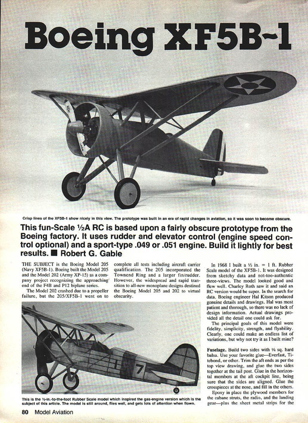
The subject is the Boeing Model 205 (Navy XF5B-1). Boeing built the Model 205 and the Model 202 (Army XP-15) as a company project recognizing the approaching end of the F4B and P12 biplane series.
The Model 202 crashed due to a propeller failure, but the 205/XF5B-1 went on to complete all tests including aircraft carrier qualification. The 205 incorporated the Townend ring and a larger fin and rudder. However, the widespread and rapid transition to all-new monoplane designs destined the Boeing Model 205 and 202 to virtual obscurity.
In 1968 I built a 1/2 in. = 1 ft. rubber-scale model of the XF5B-1. It was designed from sketchy data and not-too-authentic three-views. The model looked good and flew well. Charley Roth saw it and said an RC version would be super. In the search for data, Boeing engineer Hal Kitson produced genuine details and drawings. Hal was most patient and thorough, so there was no lack of design information. Actual drawings provided all the detail one could ask for.
The principal goals of this model were:
- Fidelity
- Simplicity
- Strength
- Flyability
Clearly, one could make an endless list of variations, but the author chose to build it as described below.
Fuselage
Build two sides with 1/8 sq. hard balsa. Use your favorite glue—Everfast, Titebond, or another suitable adhesive. Trim the aft ends as per the top-view drawing, and glue the two sides together at the tail post. Glue in the horizontal members at the aft cockpit line, being sure that the sides are aligned. Glue the crosspieces at the nose, and fill in the remaining structure.
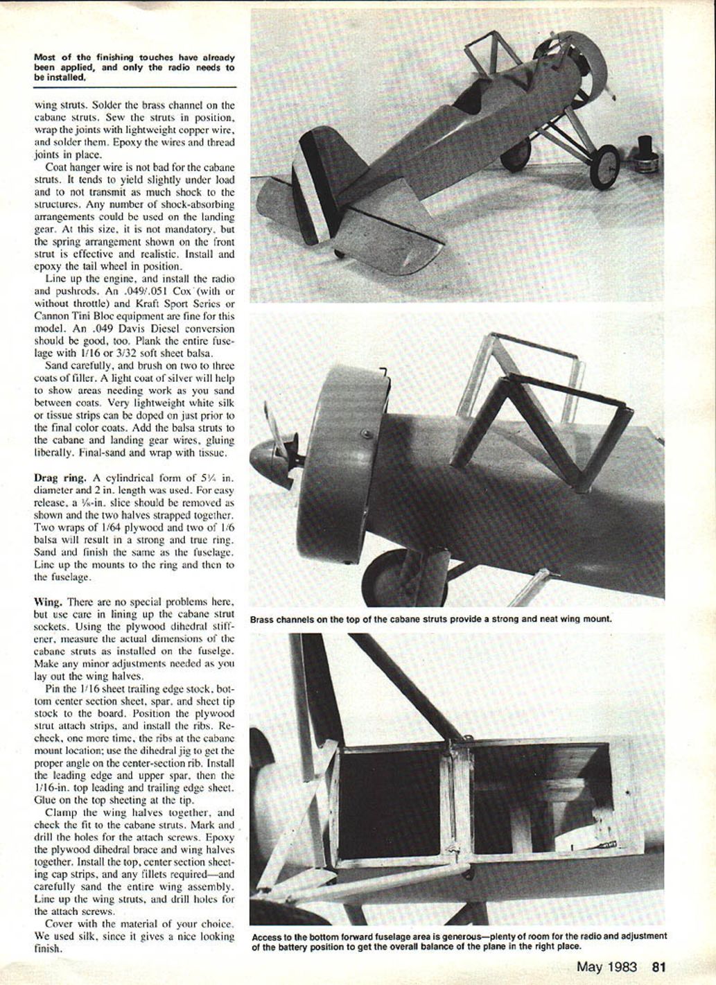
Epoxy in place the plywood members for the cabane struts, the radio, and the landing gear—plus the sheet metal strips for the wing struts. Solder the brass channel on the cabane struts. Set the struts in position, wrap the joints with lightweight copper wire, and solder them. Epoxy the wires and thread joints in place.
Coat-hanger wire is not bad for the cabane struts. It tends to yield slightly under load and does not transmit as much shock to the structure. Any number of shock-absorbing arrangements could be used on the landing gear. At this size it is not mandatory, but the spring arrangement shown on the front strut is effective and realistic. Install and epoxy the tail wheel in position.
Line up the engine and install the radio and pushrods. An .049/.051 Cox (with or without throttle) and Kraft Sport Series or Cannon Tini Bloc equipment are fine for this model. An .049 Davis Diesel conversion should be good, too. Plank the entire fuselage with 1/16 or 3/32 soft sheet balsa.
Sand carefully and brush on two to three coats of filler. A light coat of silver will help to show areas needing work as you sand between coats. Very lightweight white silk or tissue strips can be doped on just prior to the final color coats. Add the balsa struts to the cabane and landing-gear wires, gluing liberally. Final-sand and wrap with tissue.
Drag ring
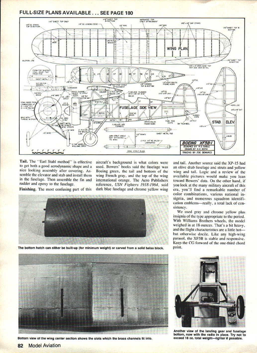
A cylindrical form of 5-1/4 in. diameter and 2 in. length was used for the drag ring. For easy release, remove a 1/8-in. slice and strap the two halves together. Two wraps of 1/64 ply and two of 1/16 balsa will result in a strong and true ring. Sand and finish the ring the same as the fuselage. Line up the mounts to the ring and then to the fuselage.
Wing
There are no special problems here, but use care in lining up the cabane strut sockets. Using the plywood dihedral stiffener, measure the actual dimensions of the cabane struts as installed on the fuselage. Make any minor adjustments needed as you lay out the wing halves.
Pin the 1/16 sheet trailing-edge stock, bottom center-section sheet, spar, and sheet tip stock to the building board. Position the plywood strut-attach strips, and install the ribs. Recheck, one more time, the ribs at the cabane mount location; use the dihedral jig to get the proper angle on the center-section rib. Install the leading edge and upper spar, then the 1/16-in. top leading and trailing-edge sheet. Glue on the top sheeting at the tip.
Clamp the wing halves together and check the fit to the cabane struts. Mark and drill the holes for the attach screws. Epoxy the plywood dihedral brace and wing halves together. Install the top center-section sheeting, cap strips, and any fillets required—and carefully sand the entire wing assembly. Line up the wing struts and drill holes for the attach screws.
Cover with the material of your choice. Silk was used on the original build because it gives a nice-looking finish.
Access to the bottom forward fuselage area is generous—plenty of room for the radio and for adjusting battery position to achieve correct overall balance.
Tail
The "Earl Stahl method" is effective for obtaining both a good aerodynamic shape and a nice-looking assembly after covering. Assemble the elevator and stabilizer and install them in the fuselage. Then assemble the fin and rudder and epoxy them to the fuselage.
Finishing
The most confusing part of this aircraft's background is what colors were used. Bowers' books say the fuselage was Boeing green, the tail and bottom of the wing French gray, and the top of the wing international orange. The Aero Publishers reference, USN Fighters 1918–1964, says a dark blue fuselage and chrome yellow wing and tail. Another source said the XP-15 had an olive drab fuselage and struts and yellow wing and tail. Logic and a review of the available pictures would make you lean toward Bowers' data. On the other hand, many military aircraft of this era show a remarkable number of color combinations, various national insignia, and numerous squadron identification emblems—really, a total lack of consistency.
We used gray and chrome yellow plus insignia of the type appropriate to the period. With Williams Brothers wheels, the model weighed in at 18 ounces. That's a bit heavy, and the flight characteristics are a little hot—but otherwise docile. Like any high-wing parasol, the XF5B is stable and responsive. Keep the center of gravity forward of the one-third chord point.
Transcribed from original scans by AI. Minor OCR errors may remain.

