
Bonanza Profile
Gene Nelson
BACK WHEN I was learning to fly the Stunt pattern, one of my favorite models was a profile Cherokee. It had a trike gear, and it hung out on the lines so well. That was over 10 years ago, and the memory still remains.
I must have burned five gallons of fuel before the thrill of inverted flight caught up with it.
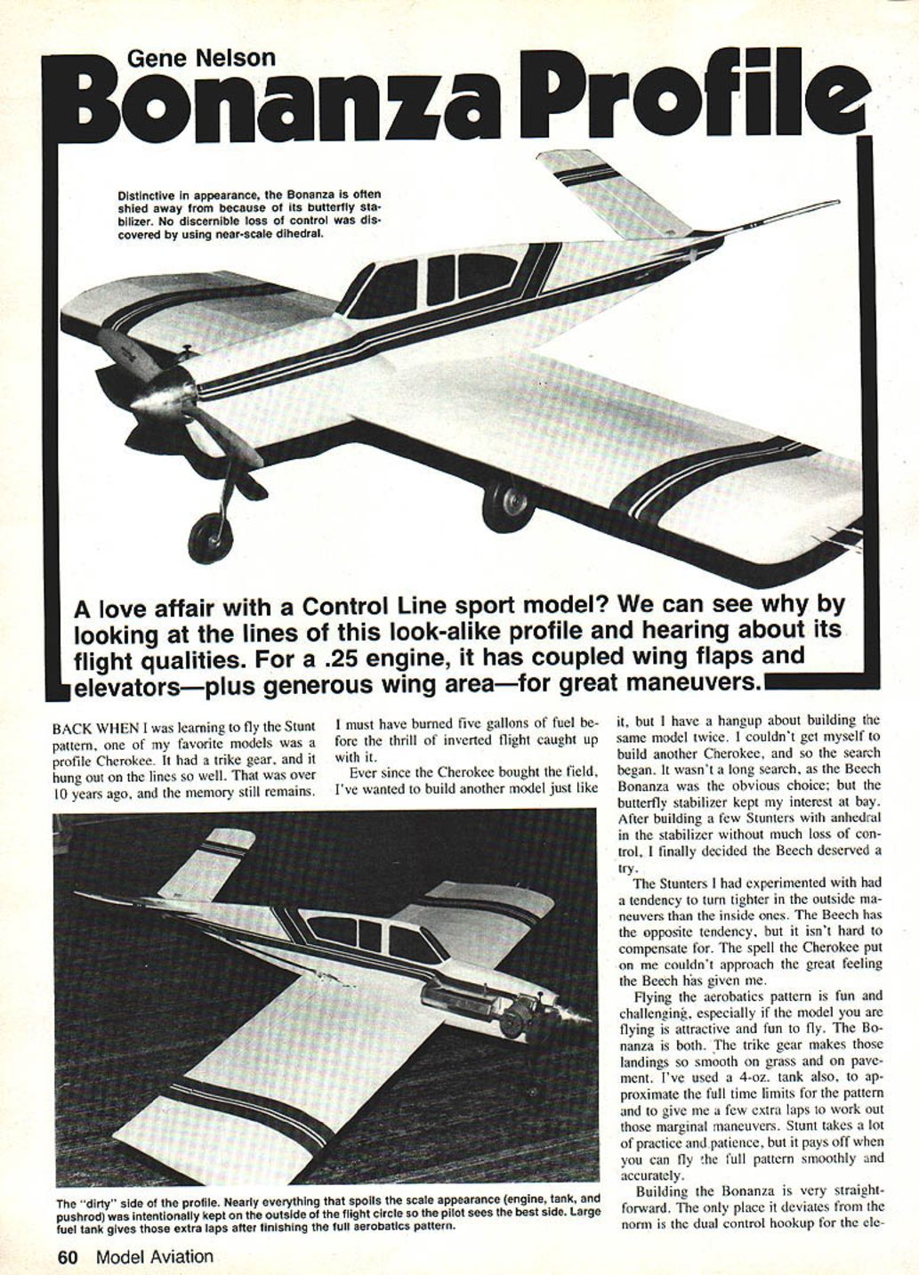
Ever since the Cherokee brought the field, I've wanted to build another model just like it, but I have a hangup about building the same model twice. I couldn't get myself to build another Cherokee, and so the search began. It wasn't a long search, as the Beech Bonanza was the obvious choice; but the butterfly stabilizer kept my interest at bay. After building a few Stunters with anhedral in the stabilizer without much loss of control, I finally decided the Beech deserved a try.
The Stunters I had experimented with had a tendency to turn tighter in the outside maneuvers than the inside ones. The Beech has the opposite tendency, but it isn't hard to compensate for. The spell the Cherokee put on me couldn't approach the great feeling the Beech has given me.
Flying the aerobatics pattern is fun and challenging, especially if the model you are flying is attractive and fun to fly. The Bonanza is both. The trike gear makes those landings so smooth on grass and on pavement. I've used a 4-oz. tank also, to approximate the full time limits for the pattern and to give me a few extra laps to work out those marginal maneuvers. Stunt takes a lot of practice and patience, but it pays off when you can fly the full pattern smoothly and accurately.
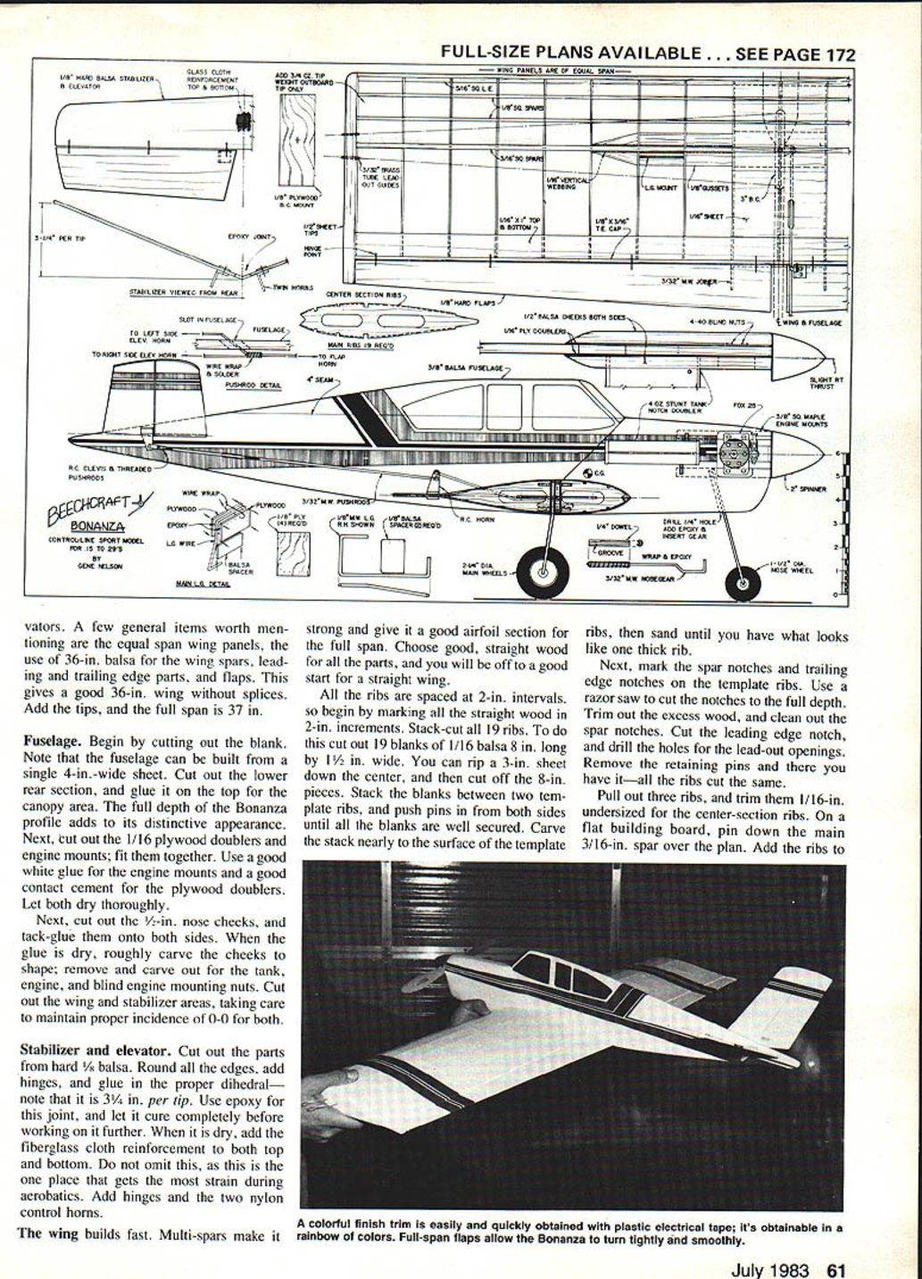
Building the Bonanza is very straightforward. The only place it deviates from the norm is the dual control hookup for the elevator. A few general items worth mentioning are the equal-span wing panels, the use of 36-in. balsa for the wing spars, leading and trailing edge parts, and flaps. This gives a good 36-in. wing without splices. Add the tips, and the full span is 37 in.
Fuselage
Begin by cutting out the blank. Note that the fuselage can be built from a single 4-in.-wide sheet. Cut out the lower rear section, and glue it on the top for the canopy area. The full depth of the Bonanza profile adds to its distinctive appearance. Next, cut out the 1/16-in. plywood doublers and engine mounts; fit them together. Use a good white glue for the engine mounts and a good contact cement for the plywood doublers. Let both dry thoroughly.
Next, cut out the 1/2-in. nose cheeks and tack-glue them onto both sides. When the glue is dry, roughly carve the cheeks to shape; remove and carve out for the tank, engine, and blind engine mounting nuts. Cut out the wing and stabilizer areas, taking care to maintain proper incidence of 0-0 for both.
Stabilizer and elevator
Cut out the parts from hard 1/8-in. balsa. Round all the edges, add hinges, and glue in the proper dihedral—note that it is 3/4 in. per tip. Use epoxy for this joint, and let it cure completely before working on it further. When it is dry, add the fiberglass cloth reinforcement to both top and bottom. Do not omit this, as this is the one place that gets the most strain during aerobatics. Add hinges and the two nylon control horns.
The wing builds fast
Multi-spars make it strong and give it a good airfoil section for the full span. Choose good, straight wood for all the parts, and you will be off to a good start for a straight wing.
All the ribs are spaced at 2-in. intervals, so begin by marking all the straight wood in 2-in. increments. Stack-cut all 19 ribs. To do this, cut out 19 blanks of 1/16-in. balsa, 8 in. long by 1 1/2 in. wide. You can rip a 3-in. sheet down the center, and then cut off the 8-in. pieces. Stack the blanks between two template ribs, and push pins in from both sides until all the blanks are well secured. Carve the stack nearly to the surface of the template ribs, then sand until you have what looks like one thick rib.
Next, mark the spar notches and trailing edge notches on the template ribs. Use a razor saw to cut the notches to the full depth. Trim out the excess wood, and clean out the spar notches. Cut the leading edge notch, and drill the holes for the lead-out openings. Remove the retaining pins and there you have it—all the ribs cut the same.
Pull out three ribs, and trim them 1/16-in. undersized for the center-section ribs. On a flat building board, pin down the main 3/16-in. spar over the plan. Add the ribs to the spar and glue in place. Add the 3/16-in. spar cap. When dry, add the top and bottom sheeting and sand smooth.
At the pre-marked locations, add the upper 3/16-in. spar, and block up the rear sections of the ribs. Before adding the glue, check for warps and correct as necessary. I suggest you use thinned white glue to brush onto each exposed joint. Thin the glue with 20% water. Next, glue on the leading edge and then each of the 1/8-in. sq. spars and trailing edge sheet. When the glue has dried, lift it and add the remaining spars, trailing edge sheet, and trailing edge cap.
Controls, etc.
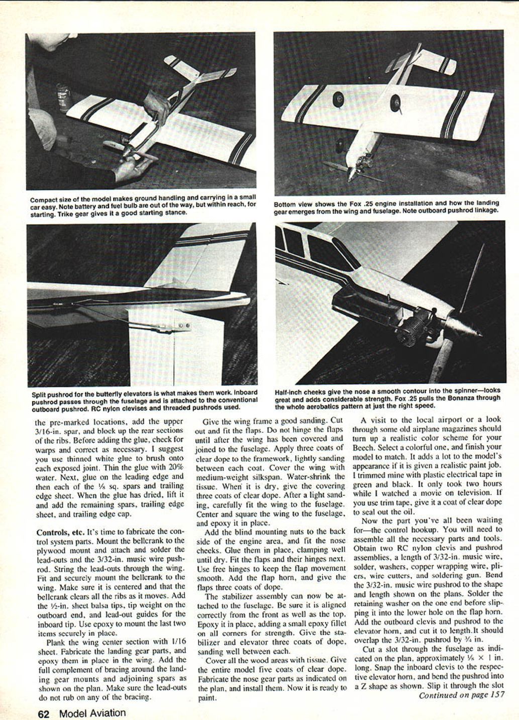
It's time to fabricate the control system parts. Mount the bellcrank to the plywood mount and attach and solder the lead-outs and the 3/32-in. music wire pushrod. String the lead-outs through the wing. Fit and securely mount the bellcrank to the wing. Make sure it is centered and that the bellcrank clears all the ribs as it moves. Add the 1/2-in. sheet balsa tips, tip weight on the outboard end, and lead-out guides for the inboard tip. Use epoxy to mount the last two items securely in place.
Plank the wing center section with 1/16-in. sheet. Fabricate the landing gear parts, and epoxy them in place in the wing. Add the full complement of bracing around the landing gear mounts and adjoining spars as shown on the plan. Make sure the lead-outs do not rub on any of the bracing.
Give the wing frame a good sanding. Cut out and fit the flaps. Do not hinge the flaps until after the wing has been covered and joined to the fuselage. Apply three coats of clear dope to the framework, lightly sanding between each coat. Cover the wing with medium-weight silkspan. Water-shrink the tissue. When it is dry, give the covering three coats of clear dope. After a light sanding, carefully fit the wing to the fuselage. Center and square the wing to the fuselage, and epoxy it in place.
Add the blind mounting nuts to the back side of the engine area, and fit the nose cheeks. Glue them in place, clamping well until dry. Fit the flaps and their hinges next. Use free hinges to keep the flap movement smooth. Add the flap horn, and give the flaps three coats of dope.
The stabilizer assembly can now be attached to the fuselage. Be sure it is aligned correctly from the front as well as the top. Epoxy it in place, adding a small epoxy fillet on all corners for strength. Give the stabilizer and elevator three coats of dope, sanding well between each.
Cover all the wood areas with tissue. Give the entire model five coats of clear dope. Fabricate the nose gear parts as indicated on the plan, and install them. Now it is ready to paint.
A visit to the local airport or a look through some old airplane magazines should turn up a realistic color scheme for your Beech. Select a colorful one, and finish your model to match. It adds a lot to the model's appearance if it is given a realistic paint job. I trimmed mine with plastic electrical tape in green and black. It only took two hours while I watched a movie on television. If you use trim tape, give it a coat of clear dope to seal out the oil.
Now the part you've all been waiting for - the control hookup. You will need to assemble all the necessary parts and tools. Obtain:
- two RC nylon clevises and pushrod assemblies
- a length of 3/32-in. music wire
- solder and washers
- copper wrapping wire
- pliers and wire cutters
- a soldering gun
Bend the 3/32-in. music wire pushrod to the shape and length shown on the plans. Solder the retaining washer on the one end before slipping it into the lower hole on the flap horn. Add the outboard clevis and pushrod to the elevator horn, and cut it to length. It should overlap the 3/32-in. pushrod by 3/8 in.
Cut a slot through the fuselage as indicated on the plan, approximately 1/2 x 1 in. Snap the inboard clevis to the respective elevator horn, and bend the pushrod into a Z shape as shown. Slip it through the slot in the fuselage, and trim it to match the lap of the other pushrods. Wrap this joint with copper wire, and solder it well. To adjust for zero-zero control, unsnap the clevis, and turn it to suit. This system works quite well; it shows no signs of binding or fatigue.
While the soldering iron is hot, add the wheels. Bind and solder the lead-outs, too. The tank is glued in place with silicone caulking glue. This keeps it in place and also helps to absorb some of the vibration. Add the engine, along with the out-thrust washers. Engine offset is important, since you do not have rudder turn to keep the lines tight. Run the fuel line and filter to the engine, add prop and spinner, and your Bonanza is ready to balance. Add lead to either end to make the model balance in the correct position, securely attaching the weight.
When the calm weather arrives, it's time to test your new ship. I had to wait for the snow to melt! Fire up the engine, get the model into the air, and you're ready for a long day at the flying field.
The Bonanza is very smooth and responsive in the air. It will turn tight corners—both inside and out. The inside corners tend to be crisper than the outside, so you may need to over-control on those outside squares. It doesn't take long to get the difference down pat. Now, just fill up the big tank, and have fun.
Transcribed from original scans by AI. Minor OCR errors may remain.

