
Boom Box
John Oldenkamp
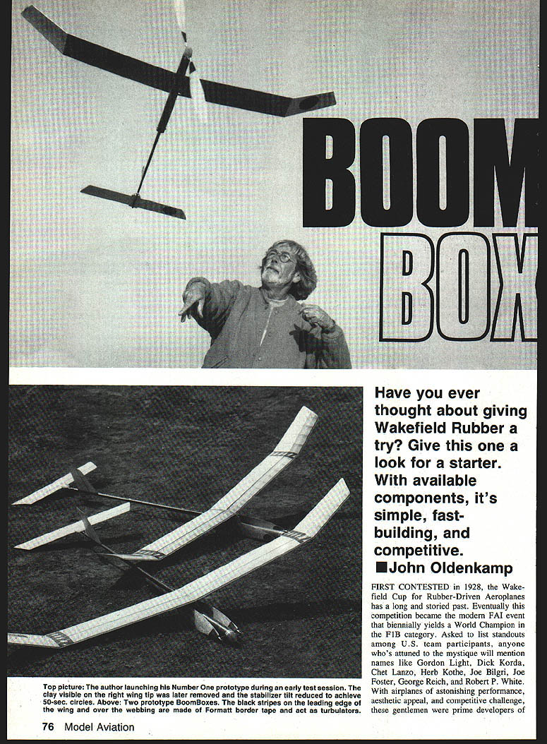
Have you ever thought about giving Wakefield rubber a try? Give this one a look for a starter. With available components, it's simple, fast-building, and competitive.
FIRST CONTESTED in 1928, the Wakefield Cup for rubber‑driven aeroplanes has a long and storied past. Eventually this competition became the modern FAI event that biennially yields a World Champion in the F1B category. Asked to list standouts among U.S. team participants, anyone attuned to the mystique will mention names like Gordon Light, Dick Korda, Chet Lanzo, Herb Kothe, Joe Bilgri, Joe Foster, George Reich, and Robert P. White. With airplanes of astonishing performance, aesthetic appeal, and competitive challenge, these gentlemen were prime developers of the event as we know it today.
Detractors point out the event is too complex, uncompromising, difficult — labor‑intensive and costly. Contrary to that view, a relative newcomer in this facet of aeromodeling has found nothing that matches the excitement and pleasure the BoomBox project has generated.
There's probably no such thing as a true beginner in Wakefield, but recent developments in technology and the elimination of the builder‑of‑the‑model rule have created the near‑possibility of ARF (almost‑ready‑to‑fly) airplanes for Free Flight. New products are appearing from a great number of cottage industries both abroad and at home. Expect a flood of overseas components as East–West trade restrictions are loosened: wing sets, fully finished front ends, tough fuselages, and other major components — perhaps even complete airplanes.
The BoomBox isn't a beginner's model, nor does it pretend to be a World Champion candidate; it is an intermediate step along the way. It's also a very serviceable, robust, competitive machine, good for dedicated practice. The BoomBox can be a winner.
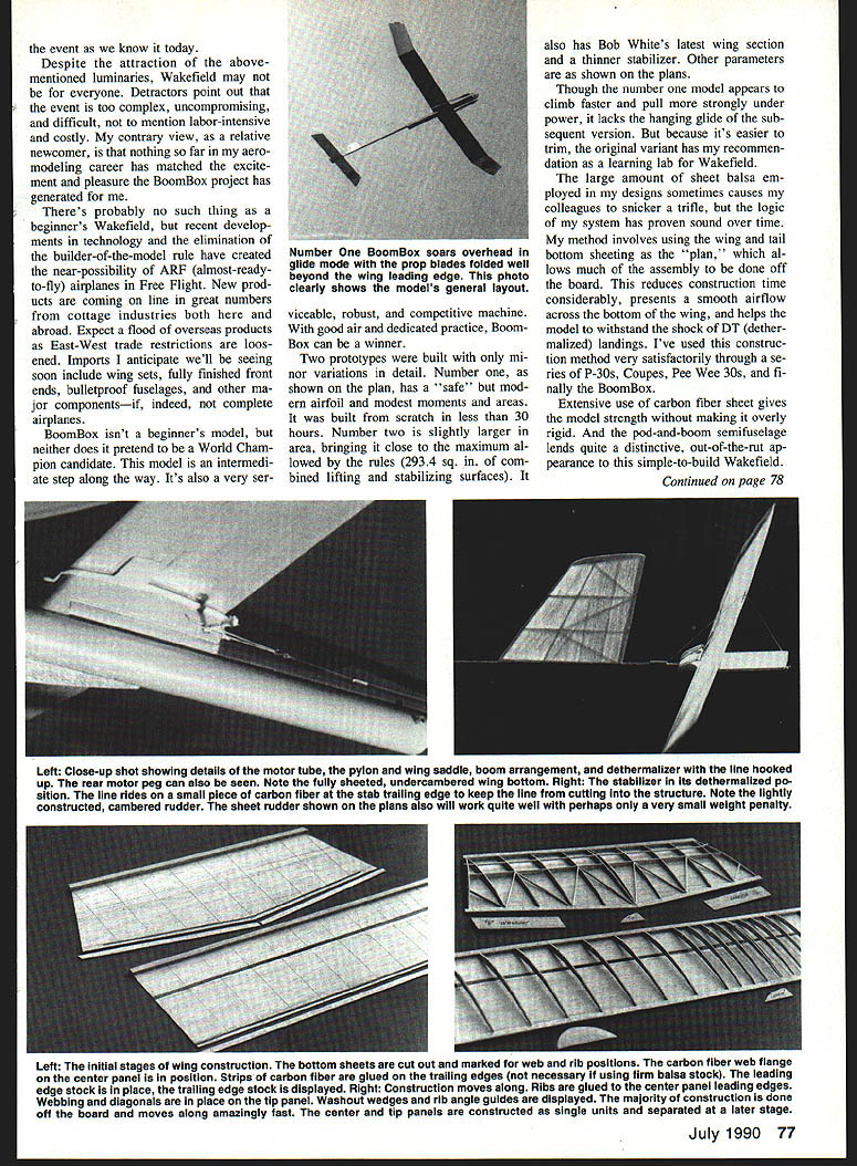
Two prototypes were built with minor variations in detail. Number One (as shown on the plan) has a safe, moderate airfoil and modest moments and areas; it can be built from scratch in less than 30 hours. Number Two is slightly larger in area, bringing it close to the rules' maximum (29.34 sq. in. combined lifting and stabilizing surfaces) and incorporates Bob White's latest wing section with a thinner stabilizer. Though Number One seems to climb faster and pull more strongly under power, it lacks the hanging glide of the later version; because it's easier to trim, the original variant is recommended for learning Wakefield.
A large amount of sheet balsa in Wakefield designs sometimes draws snickers, but the method has proven sound. The system uses wing, tail, and bottom sheeting, allowing much assembly to be done off‑board. This reduces construction time, presents smooth airflow across the bottom of the wing, and helps the model withstand shock from DT (dethermalizer) landings. I've used this method successfully through a series of P‑30s, Coupes, Pee Wee 30s, and finally the BoomBox.
Extensive use of carbon fiber sheet gives the model strength without making an overly rigid pod‑and‑boom semi‑fuselage, and it lends a distinctive appearance to an otherwise simple‑to‑build Wakefield.
Construction
What follows is not a step‑by‑step guide but a rundown of methods intended to get you on the flying field faster.
For starters:
- Select an adequate amount of quality quarter‑grained stock for the bottom surface skins; the wood should be light and straight.
- Choose medium‑weight, springy stick wood.
- Use relatively hard, speckly wood for wing ribs (about 14–15 g per 3 × 36‑in. sheet) and trailing‑edge slices.
- Use regular (thin) and medium (gap‑filling) CyA (cyanoacrylate) glue on all joints. Be sure the CyA is fresh.
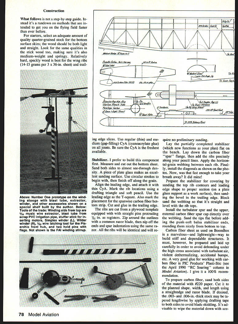
Stabilizer
I prefer to build the stabilizer first.
- Measure and cut the bottom sheet and sand both sides to almost see‑through density using a plate glass sanding surface. Start with circular strokes, then finish along the grain.
- Align and attach the leading edge with thin CyA. Mark rib locations using a drafting triangle and soft pencil, using the leading edge as a T‑square. Also mark the spanwise carbon fiber bottom strip placement.
- Cut and glue in the trailing edge. Cut ribs from a plywood template fitted with six straight pins as registers. Zip around outlines with a razor blade; nip off ends and spar indentations with the blade. All ribs will be identical and require no preliminary sanding.
- Lay the partially completed stabilizer flat; position the carbon fiber "spar" flange, then add ribs precisely on pencil lines. Apply horizontal‑grain webbing between ribs and install diagonals as shown on the plans.
- Sand top rib contours and leading edge profile on plate glass, bevel the trailing edge, and block sand the webbing flush with rib tops.
- Install the turbulator spar and the upper external carbon fiber spar cap directly over the webbing. Sand tips flat before adding the pylon‑stub stab ends, then round them from bottom to top.
Carbon fiber sheet must be prepared carefully to avoid debonding under stress. Recommended prep:
- Sand both sides with #220 paper.
- Cut to shape using a straightedge and razor blade. To taper thin stock lengthwise, apply drafting film to both sides to avoid blade skidding.
- Wipe with acetone and sand again just before gluing.
A good adhesive for carbon fiber is PIC Products' Plasti‑Stic.
Rudder
Two versions are shown on the plans. I prefer the cambered type because it helps maintain a nose‑up power pattern and initiates left glide. The sheet‑balsa version will also work; if using it, thin the aft area to allow for later tweaks.
- The cambered rudder section is a 4% Simplex airfoil. Ribs are cut from a plain template; webbing and spar inlets are eyeballed. Install a narrow .003‑in. carbon fiber cap over the webs after sanding.
- For first Wakefield projects, use the simpler sheet rudder.
Wing
The wing is the heart — possibly the soul — of BoomBox; give it care.
- Make an accurate rib template with pin registers. Cut out all ribs and sort them so the best wood is placed in the middle where stress is greatest.
- Prepare bottom sheets as with the stabilizer. Add leading edges, mark rib and carbon fiber bottom flange locations, and glue the flanges spanswise.
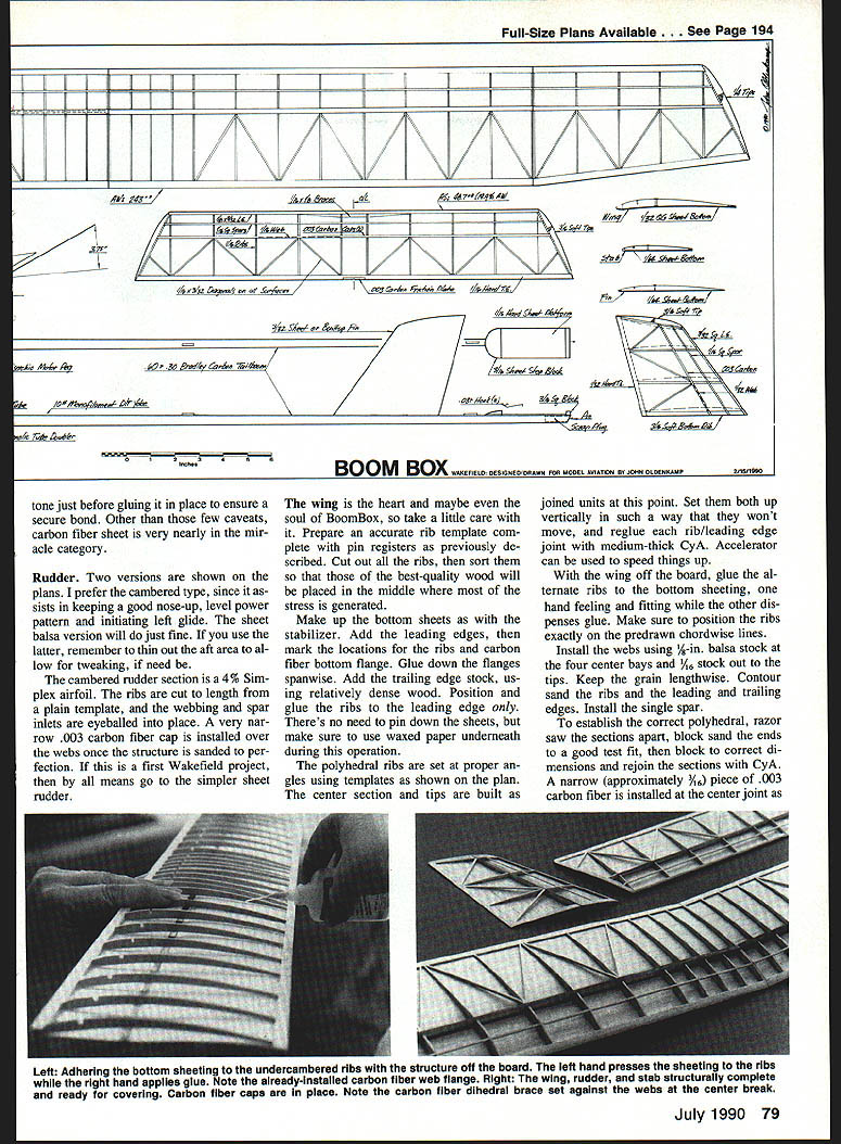
- Add the dense trailing edge stock. Position and glue ribs to the leading edge only. Use waxed paper underneath; no need to pin the sheets.
- Set polyhedral ribs at proper angles using templates. Build center section and tips as joined units. Stand them vertically and reglue each rib/leading‑edge joint with medium‑thick CyA; accelerator can speed curing.
- With the wing off the board, glue alternate ribs to the bottom sheeting, positioning ribs exactly on pre‑drawn chordwise lines. Install webs using 1/8‑in. balsa at the four center bays and 1/16‑in. out to the tips, with grain lengthwise. Contour sand ribs and leading/trailing edges and install the single spar.
- To establish correct polyhedral, razor‑saw sections apart, block‑sand ends to fit, then set dihedral and rejoin with CyA. Install a ~3/8‑in. piece of .003‑in. carbon fiber at the center joint and add bracing to the webbing on each side.
- Install diagonals end‑to‑end. Shore up tips with wedges to provide up to 3/16‑in. maximum washout. (Washout can also be added after covering if you choose not to use diagonals.) Optional left main panel washout should have been added when the trailing edge was glued.
- Add soft balsa wing tips and sand to a curved upsweep; they may be omitted with little performance penalty.
- Glue in the top carbon fiber flanges over the webbing. Pre‑glue with Plasti‑Stic if any ripples appear. Check surface integrity and sand smooth.
Cover the wing, stabilizer, and rudder while other work continues. Cover both sides using the traditional nitrate‑dope precoat and stick‑down method: spray lightly with rubbing alcohol, allow to dry, then apply four coats of thin nitrate dope, sanding lightly between coats. Allow to cure.
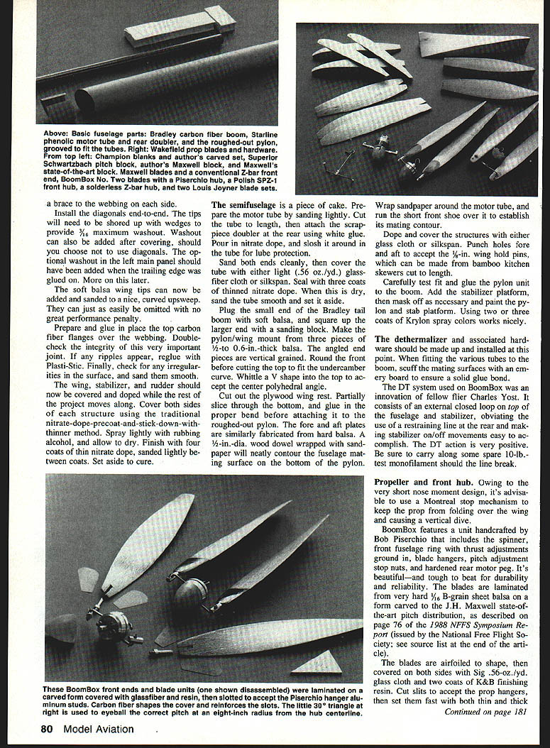
Semifuselage, Pylon and Boom
- Prepare the motor tube: sand lightly and cut to length. Attach a scrap doubler at the rear with white glue. Pour in thinned nitrate dope and slosh for protection. Sand both ends and cover with light (.56 oz./yd.) glass cloth or silkspan; seal with three coats of thinned nitrate dope. Sand smooth when dry.
- Plug the small end of the tail boom with soft balsa and square the larger end. Make the pylon/wing mount from three pieces of 1/2–5/16‑in. thick balsa; angled end pieces should be vertical grained. Round the front before cutting the top to fit the undercamber curve, and whittle a V‑shape into the top to accept the center polyhedral angle.
- Cut the plywood wing rest, partially rout the bottom and glue in the proper bend before attaching to the roughed‑out pylon. Fabricate fore and aft plates from hard balsa and contour the fuselage mating surface with a wrapped dowel.
- Wrap sandpaper around the motor tube and run the short front shoe over it to establish mating contours. Dope and cover the pylon and attach holes for 1/4‑in. wing hold pins (bamboo skewers cut to length work well).
- Test fit and glue the pylon unit to the boom, add the stabilizer platform, then mask and paint the pylon and stab platform (two or three coats of Krylon spray work nicely).
When mating the boom to tubes and other fittings, scuff mating surfaces with an emery board to ensure a solid glue bond. The joint of the boom to the motor tube is the single dicey operation: block and jig for perfect alignment, spot‑glue with CyA, and be prepared to debond and start over if alignment is off.
Dethermalizer (DT) System
The DT used on BoomBox is an innovation by Charles Yost. It consists of an external closed loop on top of the fuselage and stabilizer, eliminating the need for a restraining line at the rear and making stabilizer on/off movements easy. The action is very positive. Carry spare 10‑lb‑test monofilament in case the line breaks.
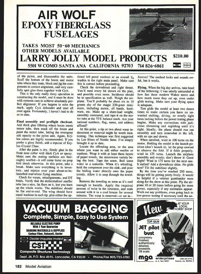
Propeller and Front Hub
Because of the very short nose moment design, use a Montreal stop mechanism to prevent the prop from folding over the wing and causing a vertical dive.
BoomBox uses a handcrafted front unit by Bob Piserchio, which includes spinner, front fuselage ring with thrust adjustments, blade hangers, pitch adjustment stop nuts, and a hardened rear motor peg. Blades are laminated from very hard 1/16‑in. B‑grain sheet balsa on a form carved to the J. H. Maxwell state‑of‑the‑art pitch distribution (see J. H. Maxwell reference). Blades are airfoiled, covered both sides with Sig .56‑oz./yd. glass cloth and two coats of K&B finishing resin, then slits are cut to accept the prop hangers and secured with thin and thick CA. Cap hangers with small carbon‑fiber pieces and finish with three thin coats of Krylon Crystal Clear #1301 spray.
The BoomBox propeller is 26 in. diameter with 30° outthrust from center and provides strong pulling power. If you don't want to carve your own pitch block and lay up your prop, ready‑made blades and hubs are available from several suppliers listed below.
Final Assembly and Preflight Checkout
- Scuff the boom under the rudder area and install the rudder on the boom centerline aligned with the top vertical sight line. Drill the motor tube for the rear peg, install the motor, hook up the DT line, and secure to the motor tube and rear peg.
- Dry‑fit wing and stabilizer; check the DT system and all flight controls.
- Suspend the model from a string set at 75% of the root chord (3.75 in.) to ensure balance is level fore and aft. If not, adjust motor position or add ballast until balanced. Mark the forward balance point on the pod and add nose ballast as required.
- Install landing gear per plan and reinforce pod bottom where the gear passes through with a small plywood pad. Fit wheels with small tubing washers as thrust bearings.
- Add thick glue filleting where boom meets motor tube, mask the boom, and paint the motor tube (overspray will add opacity to the pylon unit). Finish with Krylon colors and an optional topcoat of Krylon Crystal Clear for gloss.
- After paint is dry, glue in the front nose collar with thick CyA or epoxy; scuff mating surfaces first to prevent separation on prop fold shock.
Check for warps, misalignments, and DT binds. Verify the dethermalizer snuffer tube flare. The stabilizer should be flat end‑to‑end. The wing should have equal washout in each tip, plus either the optional left panel washout or an overall 1/8" wash in the right main panel. Check downthrust and right thrust — you'll need both. Incidence should match specifications.
You will probably be about 6–10 g shy of the 230‑g minimum (including motor, boards, hardware). Make a smoothly contoured sheet‑lead weight and tape it to the motor tube at the 75% balance mark if needed. Affix national numbers, flag, name, and address per rules.
Warp induction/removal (Lee Hines method, updated)
- Locate the area to change.
- Wrap with at least three layers of paper towels and tape the seam.
- Boil water in a teakettle. Hold the component over the sink and pour boiling water onto the towels to let it seep into the structure.
- Remove towels when cool enough to handle. Apply the required twist, then hold the part in a cool breeze for several minutes.
The method looks and sounds harsh, but it works to set or remove warps.
Trimming and Flying
- Test‑glide the model many times (dozens) to uncover any stalling, diving, or overly tight turning tendencies before power testing. Make corrections with shims and re‑gluing until the glide is smooth and turns somewhat to the left with no oscillations.
- When satisfied, wind 100 turns on the motor and, holding the model in the launch position (do not launch), observe prop fold on unwind. If it folds properly, wind 125 turns and repeat. Launch smoothly and evenly — do not throw.
- If flight is good, gradually increase turns: 175, 250, etc. Expect lively behavior as you approach higher turns; an experienced gumbander is helpful at that stage.
- Fly the airplane 10–20 times before pushing for more power, and revert to low‑power testing if anomalies appear until the cause is clear.
I flew a prototype under contest conditions at 369 turns (not recommended for a first full‑power attempt). The plane managed to max six out of eight flights in cool, breezy weather at the October 1989 FAI team selection semifinals at Lost Hills, CA.
Postscript
BoomBox Number Three is nearing completion with changes to optimize the design while retaining the outlines:
- Motor tube lengthened one inch to accommodate a thinner batch of rubber for a tighter motor and fail‑safe prop stop operation.
- Wing undercamber increased from nominal 6% to 8%; top camber (USA 5) remains.
- A shoe‑type stabilizer mount is being incorporated to prevent prop‑fold shock from pulling the stab off its perch.
- A new, higher aspect‑ratio prop outline will be tried with Andrijuvek pitch distribution.
Write to 3331 Adams Ave., San Diego, CA 92116 for further data, information, and problem solving.
Sincere thanks to Robert P. White — many‑time U.S. Wakefield team member, World Champion, and acknowledged maestro — for advice and encouragement in developing the BoomBox series.
Sources
- Aerodyne, 603‑B San Michel North, Costa Mesa, CA 92627: quality nitrate dope, thinner, covering adhesive.
- Bradley Model Products, 1337 Pine Sap Court, Orlando, FL 32825: carbon fiber tail booms, carbon fiber sheet.
- Champion Model Products, 880 Carmen Court, La Verne, CA 91750: prop blanks, Z‑bars, good tissue, balsa, kits.
- Composite Structures Technology, 3701 Inglewood Ave., #268, Redondo Beach, CA 90278‑1110: glassfiber cloth, carbon fiber sheet.
- FAI Model Supply, P.O. Box 3957, Torrance, CA 90510: Morrill winders, winding hooks, stirrups, FAI tan rubber strip, Simple Stooge winding aid.
- Free Flight Consultants, 5257 Stone Court, San Diego, CA 92115: Piserchio propeller hubs, motor tube fittings.
- Louis Joyner, 3657 Brookwood Rd., Birmingham, AL 35223: precision laminated prop blades in several pitches and shapes.
- J. H. Maxwell, Aids for Advanced Aeromodelling, 14 Upper Craig's, Stirling, FK8 2DG, Scotland: preformed prop blades, hatch blocks, sheet wings, rib sets to order, jigs, state‑of‑the‑art propeller pitch blocks.
- Model Research Labs, 25108 Marguerite #160, Mission Viejo, CA 92692: carbon fiber sheet and other composites, PIC Plasti‑Stic glue for carbon fiber sheet.
- National Free Flight Society (see NFFS publications and symposium reports for further references).
Transcribed from original scans by AI. Minor OCR errors may remain.

