
Bow Flex Foam Cutter
T. Michael Jennings
The development and use of foam wings began many years ago. Still, there are typically only a few modelers in each club who have the equipment and the ability to cut foam wings.
Building a foam wing with a warp in it is very difficult; foam wings are essentially straight. Thus your model will fly with increased predictability. Building multiple foam wings with the same airfoil becomes easy, and takes less time than built-up wings.
This article describes an easy-to-build, economical, efficient power supply and nichrome wire bow for cutting foam. The primary use of the foam cutter is to cut wings for radio control and control line models, and fuselage parts. A person with basic building skills can build a nichrome wire bow for about $30.
Safety Precautions
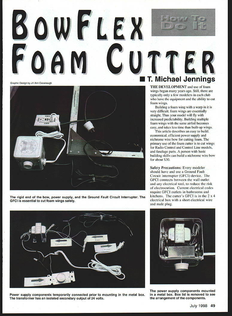
- Every modeler should have and use a Ground Fault Circuit Interrupter (GFCI). The GFCI connects between the wall outlet and any electrical tool to reduce the risk of electrocution. Current electrical codes require GFCI outlets in bathrooms and kitchens. The cutter's GFCI is mounted in the 2 x 4 electrical box with a short electrical wire and male plug.
- The second safety device is an isolated transformer. This type of transformer separates the primary electrical input from the secondary electrical output.
- Cutting a foam wing is a two-person job — one person at each end of the bow. This provides increased safety and greater control while cutting the foam block.
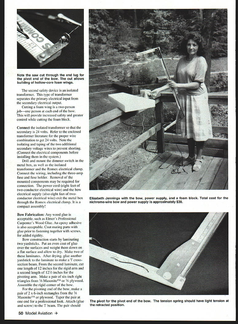
Connect the isolated transformer so that the secondary is 24 volts. Refer to the transformer literature for the proper wire combination to get 24 volts. Be sure to insulate and tape the two additional secondary wires to prevent shorting. (Connect the electrical components before installing them in the system.)
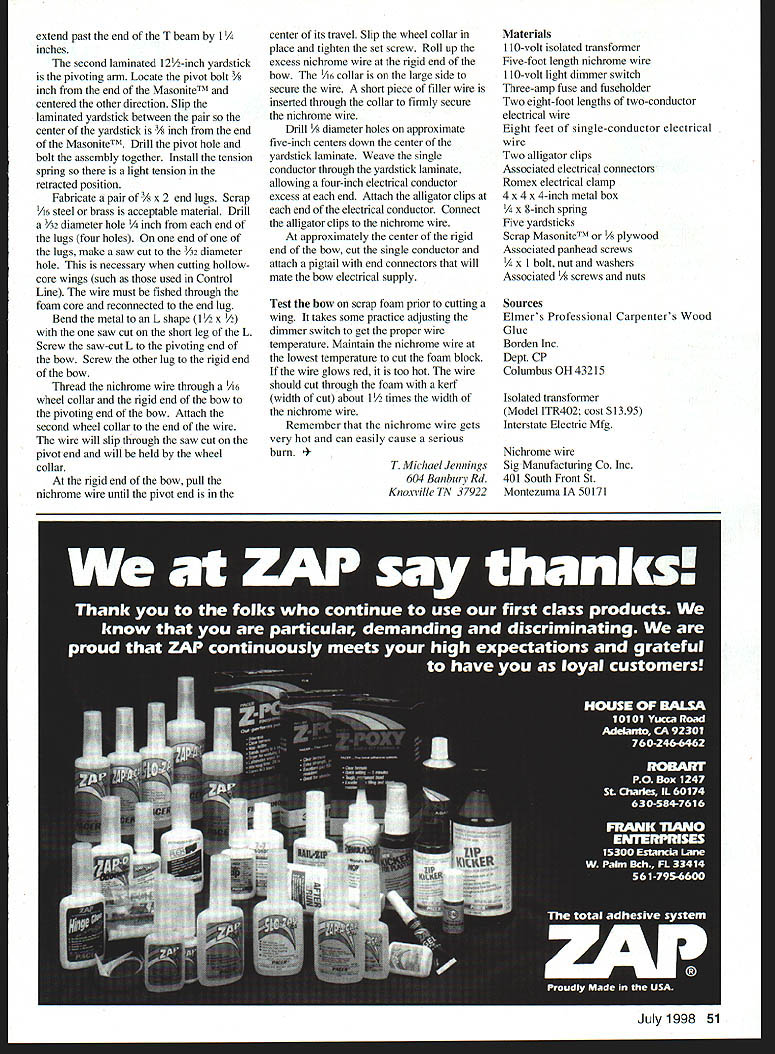
Drill and mount the dimmer switch in the metal box, as well as the isolated transformer and the Romex electrical clamp. Connect the wiring, including the three-amp fuse and fuse holder. Removal of the mounted components may be required for access during connection. The power cord (eight feet of two-conductor electrical wire) and the bow electrical supply (also eight feet of two-conductor electrical wire) exit the metal box through the Romex electrical clamp. It is a compact assembly.
Bow Fabrication
Any wood glue is acceptable, such as Elmer's Professional Carpenter's Wood Glue. An epoxy adhesive is also acceptable. Coat mating parts with glue prior to fastening with screws for added rigidity.
- Laminate two yardsticks: put an even coat of glue over the surfaces, weight them down on a flat surface, and allow to dry. Make two of these laminates.
- After drying, glue another yardstick to one laminate to make a T cross-section beam.
- From the second laminate, cut one length of 12 inches for the rigid arm and a second length of 12-1/2 inches for the pivoting arm.
- Make a pair of six-inch right triangles from 1/8-inch Masonite or 1/8-inch plywood. Assemble the rigid corner of the bow (glue and screw the triangles to the T beam).
- For the pivoting end, make a pair of 2 x 6-inch rectangles from 1/8-inch Masonite or plywood. Taper the pair at one end for a professional look. Attach (glue and screw) them to the T beam.
Locate the pivot bolt 3/8 inch from the end of the Masonite, centered the other direction. Slip the laminated yardstick between the pair; center the yardstick 3/8 inch from the end of the Masonite. Drill the pivot hole and bolt the assembly together. Install the tension spring so there is light tension in the retracted position.
Fabricate a pair of 3/8-by-2-inch end lugs from scrap 1/16-inch steel or brass. Drill 3/32-inch diameter holes in the end lugs. Make a saw cut and a 3/32-inch diameter hole as necessary for cutting hollow-core wings, such as those used where control-line wire must be fished through the foam core and reconnected to the end lug. Bend the metal into an L shape with a short leg to fit the saw cut. Screw the saw-cut L to the pivoting end bow and screw the other lug to the rigid end bow.
Thread the nichrome wire through a wheel collar on the rigid end bow and through the pivoting end bow. Attach a second wheel collar to the end of the wire. The wire will slip through the saw cut at the pivot end and be held by the wheel collar at the rigid end. At the rigid end of the bow, pull the nichrome wire until the pivot end is in the center of its travel. Slip the wheel collar in place and tighten the set screw. Roll up the excess nichrome wire at the rigid end of the bow. The 1/16-inch collar is slightly large to secure the wire; insert a short piece of filler wire through the collar to firmly secure the nichrome wire.
Drill 5/8-inch diameter holes on approximately five-inch centers down the center of the yardstick laminate. Weave the single conductor through the yardstick laminate, leaving a four-inch electrical conductor excess at each end. Attach the alligator clips to each end of the electrical conductor and connect the clips to the nichrome wire.
At approximately the center of the rigid end of the bow, cut the single conductor and attach a pigtail with end connectors that will mate with the bow electrical supply.
Test the bow on scrap foam prior to cutting a wing. It takes some practice adjusting the dimmer switch to get the proper wire temperature. Keep the nichrome wire at the lowest temperature that will cut the foam. If the wire glows red, it is too hot. The wire should cut through the foam with a kerf (width of cut) about 1-1/2 times the diameter of the nichrome wire.
Remember that the nichrome wire gets very hot and can easily cause a serious burn.
T. Michael Jennings 604 Banbury Rd. Knoxville, TN 37922
Materials
- 110-volt isolated transformer
- Five-foot length of nichrome wire
- 110-volt light dimmer switch
- Three-amp fuse and fuse holder
- Two eight-foot lengths of two-conductor electrical wire
- Eight feet of single-conductor electrical wire
- Two alligator clips
- Associated electrical connectors
- Romex electrical clamp
- 4 x 4 x 4-inch metal box
- 1/4 x 8-inch spring
- Five yardsticks
- Scrap Masonite or 1/8-inch plywood
- Associated panhead screws
- 1/4 x 1-inch bolt, nut, and washers
- Associated 1/4-inch screws and nuts
Sources
- Elmer's Professional Carpenter's Wood Glue
Borden Inc., Dept. CP, Columbus, OH 43215
- Isolated transformer (Model TR402; cost $13.95)
Interstate Electric Mfg.
- Nichrome wire
Sig Manufacturing Co. Inc., 401 South Front St., Montezuma, IA 50171
Transcribed from original scans by AI. Minor OCR errors may remain.

