
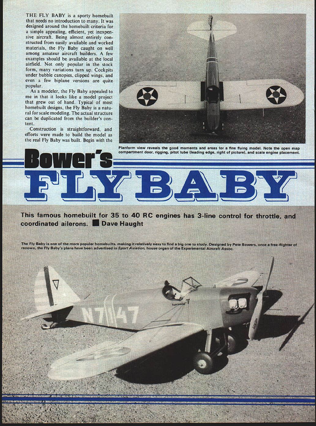
THE FLY BABY is a sporty homebuilt that needs no introduction to many. It was designed around the homebuilt criteria for a simple appealing, efficient, yet inexpensive aircraft. Being almost entirely constructed from easily available and worked materials, the Fly Baby caught on well among amateur aircraft builders. A few examples should be available at the local airfield. Not only popular in the stock form, many variations turn up. Cockpits under bubble canopies, clipped wings, and even a few biplane versions are quite popular.
As a modeler, the Fly Baby appealed to me in that it looks like a model project that grew out of hand. Typical of most homebuilt designs, the Fly Baby is a natural for scale modeling. The actual structure can be duplicated from the builder's content.
Construction is straightforward, and efforts were made to build the model as the real Fly Baby was built. Begin with the
Bower's Fly Baby
This famous homebuilt for 35 to 40 RC engines has 3-line control for throttle, and coordinated ailerons. ■ Dave Haught
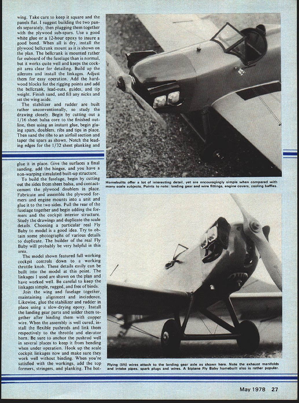
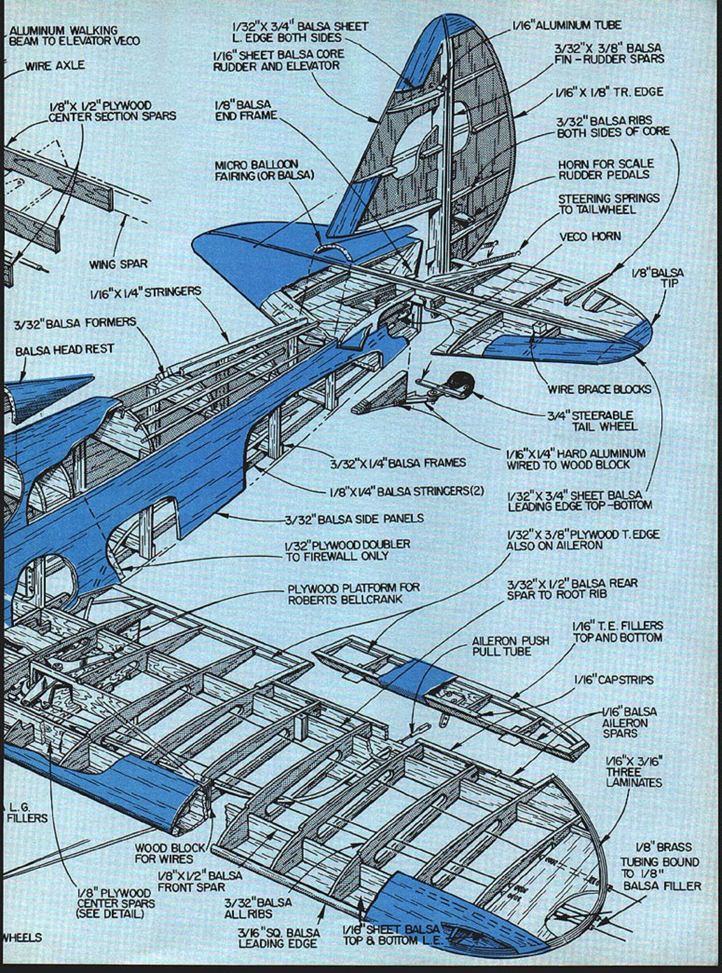
The Fly Baby is one of the more popular homebuilts, making it relatively easy to find a big one to study. Designed by Pete Bowers, once a tree-fighter of renown, the Fly Baby's plans have been advertised in Sport Aviation, house organ of the Experimental Aircraft Assoc. wing. Take care to keep it square and the panels flat. I suggest building the two panels separately, then plugging them together with the plywood sub-spars. Use a good white glue or a 12-hour epoxy to insure a good bond. When all is dry, install the plywood bellcrank mount as it is shown on the plan. The bellcrank is mounted rather far outboard of the fuselage than is normal, but it works quite well and keeps the cockpit area clear for detailing. Build up the ailerons and install the linkages. Adjust them for easy operation. Add the hardwood blocks for the rigging points and add the bellcrank, lead-outs, guides, and tip weight. Finish sand, and fill any nicks and set the wing aside.
The stabilizer and rudder are built rather unconventionally, so study the drawing closely. Begin by cutting out a 1/16 sheet balsa core to the finished outline, then using an instant glue, begin gluing spars, doublers, ribs and tips in place. Then sand the ribs to an airfoil section and taper the spars as shown. Notch the leading edges for the 1/32 sheet planking and glue it in place. Give the surfaces a final sanding, add the hinges, and you have a non-warping simulated built-up structure.
To build the fuselage, begin by cutting out the sides from sheet balsa, and contact-cement the plywood doublers in place. Fabricate and assemble the plywood formers and engine mounts into a unit and glue it to the two sides. Pull the rear of the fuselage together and begin adding the formers and the cockpit interior structure. Study the drawings and duplicate the scale details. Choosing a particular real Fly Baby to model is a good idea. Try to obtain some photographs of various details to duplicate. The builder of the real Fly Baby will probably be very helpful in this area.
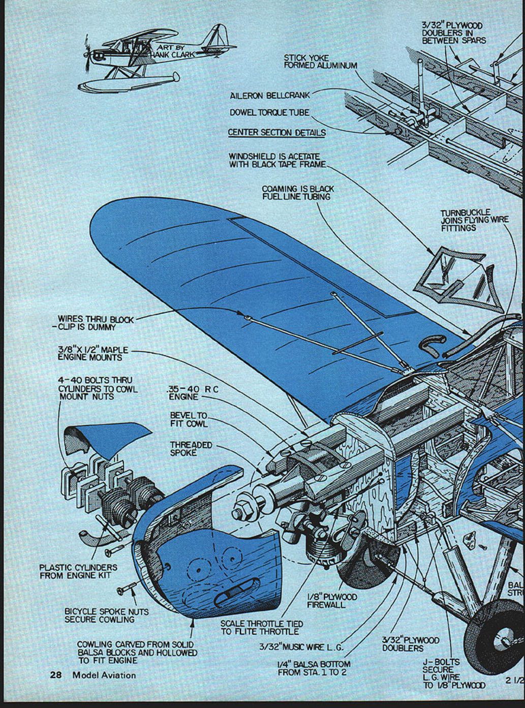
The model shown featured full working cockpit controls down to a working throttle knob. These details easily can be built into the model at this point. The linkages I used are shown on the plan and have worked well. Be careful to keep the linkages simple, rugged, and free of binds.
Join the wing and fuselage together, maintaining alignment and incidence. Likewise, glue the stabilizer and rudder in place using a slow-drying epoxy. Install the landing gear parts and solder them together after binding them with copper wire. When the assembly is well cured, install the flexible pushrods and link them respectively to the throttle and elevator horn. Be sure to anchor the pushrod well in several places to keep it from bending when under operation. Hook up the scale cockpit linkages now and make sure they work well without binding. When you're satisfied with the workings, add the top formers, stringers, and planking. The bottom stringers and planking.
CENTER SECTION DETAILS
ART BY HANK CLARK
3/32" PLYWOOD DOUBLERS IN BETWEEN SPARS
STICK YOKE FORMED ALUMINUM
AILERON BELLCRANK
DOWEL TORQUE TUBE
WINDSHIELD IS ACETATE WITH BLACK TAPE FRAME
COAMING IS BLACK FUEL LINE TUBING
TURNBUCKLE JOINS FLYING WIRE FITTINGS
WIRES THRU BLOCK — CLIP IS DUMMY
3/8" x 1/2" MAPLE ENGINE MOUNTS
4-40 BOLTS THRU CYLINDERS TO COWL MOUNT NUTS
.35–.40 R/C ENGINE
BEVEL TO FIT COWL
THREADED SPOKE
PLASTIC CYLINDERS FROM ENGINE KIT
BICYCLE SPOKE NUTS SECURE COWLING
COWLING CARVED FROM SOLID BALSA BLOCKS AND HOLLOWED TO FIT ENGINE
SCALE THROTTLE TIED TO FLITE THROTTLE
3/32" MUSIC WIRE L.G.
1/4" BALSA BOTTOM FROM STA. 1 TO 2
1/8" PLYWOOD FIREWALL
3/32" PLYWOOD DOUBLERS
J-BOLTS SECURE L.G. WIRE TO 1/8" PLYWOOD
BALLAST STRAP ALUMINUM WALKING BEAM TO ELEVATOR VECO
WIRE AXLE
1/8" x 1/2" PLYWOOD CENTER SECTION SPARS
WING SPAR
1/16" x 1/4" STRINGERS
3/32" BALSA FORMERS
BALSA HEAD REST
L.G. FILLERS
WHEELS
WOOD BLOCK FOR WIRES
1/8" x 1/2" BALSA FRONT SPAR
1/8" PLYWOOD CENTER SPARS (SEE DETAIL)
3/32" BALSA ALL RIBS
3/16" SQ. BALSA LEADING EDGE
1/16" SHEET BALSA TOP & BOTTOM L.E.
3/32" x 1/4" BALSA FRAMES
1/8" x 1/4" BALSA STRINGERS (2)
3/32" BALSA SIDE PANELS
1/32" PLYWOOD DOUBLER TO FIREWALL ONLY
PLYWOOD PLATFORM FOR ROBERTS BELLCRANK
1/32" x 3/4" BALSA SHEET L. EDGE BOTH SIDES
1/16" SHEET BALSA CORE RUDDER AND ELEVATOR
1/8" BALSA END FRAME
MICRO BALLOON FAIRING (OR BALSA)
1/16" ALUMINUM TUBE
3/32" x 3/8" BALSA FIN - RUDDER SPARS
1/16" x 1/8" TR. EDGE
3/32" BALSA RIBS BOTH SIDES OF CORE
HORN FOR SCALE RUDDER PEDALS
STEERING SPRINGS TO TAILWHEEL
VECO HORN
1/8" BALSA TIP
WIRE BRACE BLOCKS
3/4" STEERABLE TAIL WHEEL
1/16" x 1/4" HARD ALUMINUM WIRED TO WOOD BLOCK
1/32" x 3/4" SHEET BALSA LEADING EDGE TOP - BOTTOM
1/32" x 3/8" PLYWOOD T. EDGE ALSO ON AILERON
3/32" x 1/2" BALSA REAR SPAR TO ROOT RIB
AILERON PUSH PULL TUBE
1/16" T.E. FILLERS TOP AND BOTTOM
1/16" CAPSTRIPS
1/16" BALSA AILERON SPARS
1/16" x 3/16" THREE LAMINATES
1/8" BRASS TUBING BOUND TO 1/8" BALSA FILLER
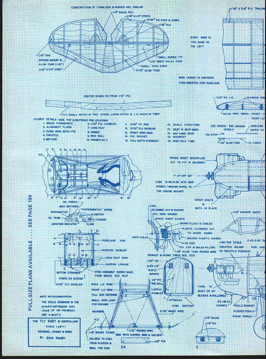
CONSTRUCTION OF STABILIZER & RUDDER ARE SIMILAR
1/8" BALSA FILL 1/16" x 1/8" STRIP 3/32" SQ. RIBS & SPARS 1/32" PLY.
1/8" TIPS SPRUCE INSERT & ALUM. TUBE (1/16") 1/32" x 3/4" SHEET
SMALL HINGES TYP. 1/16" SHEET BALSA CORE SMALL VECO HORN 3/32" ALUM. TUBE
RIGHT WING IS THE SAME AS THE LEFT
WING IS BUILT IN ONE PIECE THEN INSERTED INTO FUSELAGE
CENTER SPARS (3) FROM 1/8" PLY.
CUT SMALL NOTCH IN TWO SPARS, LARGE NOTCH & L.G. HOLES IN THIRD
COCKPIT DETAILS: SIDE, TOP & SECTIONS FOR LOCATIONS
- BRASS TURNBUCKLE
- ALIGNMENT PLATES
- FLYING WIRE ATTCH. FTG.
- THROTTLE
- MIXTURE
- 1/32" PLY DOUBLER
- CARB. HEAT
- PRIMER
- SKID BALL
- FORMER NO. 2
- 3/32" ST. SIDE
- 3/32" PLY DOUBLER
- FRONT WING SPAR
- PLY. SOCKET
- FULL DEPTH STRINGER
- SCALE STRUCTURE
- SEAT & SEAT BELTS
- MAP COMP. DOOR
- HEADREST
- WING FOLD TUBE
BRASS SHEET SCOOPS ARE CUT TO FIT & SOLDERED
1/8" - 2° OFF SET
COWL IS HELD ON WITH BIKE SPOKES THROUGH COWL TO THE ENGINE MOUNTS
EPOXY BOLTS & NUTS IN PLACE
SPARK PLUGS & CABLES
PLASTIC CYLINDERS CUT TO SHAPE SHOWN
MOLDED PLASTIC COVERS
4-40 BOLT
PLY. CAP & BALSA FILLERS
ALUM. TUBE ROCKER ARMS
EXHAUST & INTAKE TUBES SEE TEXT
NOTE HOLES
COWL IS BUILT UP OF BLOCKS HOLLOWED
COWL SECTION
3/32" MUSIC WIRE
1/8" BALSA 1/8" PLY
RUDDER PEDALS BRAKE PEDALS
LINK FOR SCALE THROTTLE SOLDER TO THROTTLE PUSHROD
2 V-2-3 OZ. TANKS
SCALE EXHAUST
NOTE ON DOCUMENTATION: THE SCALE DRAWINGS IN THE AUGUST/SEPTEMBER 1963 ISSUE OF AIR PROGRESS ARE A MUST!!
FULL-SIZE PLANS AVAILABLE — SEE PAGE 104
OIL PRESS. MAG SWITCHES TACHOMETER "*EXPERIMENTAL*" NOTICE ALTIMETER OIL TEMP COMPASS AIRSPEED INDICATOR CLIMB
BOTTOM STRINGERS FABRIC ON BOTTOM 3/32" PLY DOUBLER
FUSELAGE SIDE PLYWOOD DOUBLER WING ROOT SPAR AILERON LINKAGE
STICK ASSEMBLY ENTRY MADE FROM BRASS (SEE TEXT)
BACK L.G. WIRE FRONT L.G. WIRE FULL SIZE PATTERNS SMALL WIRE LOOP FOR RIGGING WASHERS
1/8" BRASS TUBES BEND WITH COPPER WIRE & SOLDER 1/32" RIGGING WIRE
THE FLY BABY IN CONTROL-LINE SCALE 1 1/2" = 1' DESIGNED, DRAWN & INKED BY dave hough CAPPED WITH 1/16" x 3/16" BALSA
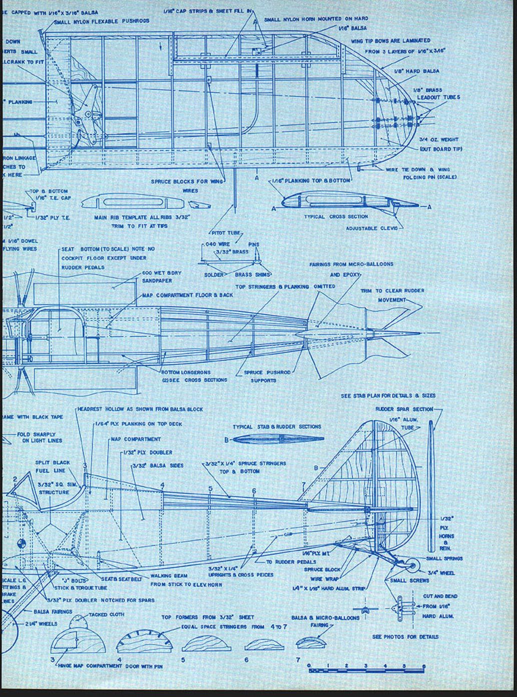
SMALL NYLON FLEXIBLE PUSHRODS
1/16" CAP STRIPS & SHEET FILL
SMALL NYLON HORN MOUNTED ON HARD 1/16" BALSA
WING TIP BOWS ARE LAMINATED FROM 3 LAYERS OF 1/16" x 3/16"
1/8" HARD BALSA
1/8" BRASS LEADOUT TUBES
3/4 OZ. WEIGHT (OUTBOARD TIP)
WIRE TIE DOWN & WING FOLDING PIN (SCALE)
SPRUCE BLOCKS FOR WING WIRES
1/16" PLANKING TOP & BOTTOM
MAIN RIB TEMPLATE ALL RIBS 3/32" TRIM TO FIT AT TIPS
TYPICAL CROSS SECTION
ADJUSTABLE CLEVIS
PITOT TUBE
.040 WIRE PINS 3/32" BRASS
SOLDER BRASS SHIMS
FAIRINGS FROM MICRO-BALLOONS AND EPOXY
TOP STRINGERS & PLANKING OMITTED
TRIM TO CLEAR RUDDER MOVEMENT
SEAT BOTTOM (TO SCALE) NOTE NO COCKPIT FLOOR EXCEPT UNDER RUDDER PEDALS
600 WET & DRY SANDPAPER
MAP COMPARTMENT FLOOR & BACK
BOTTOM LONGERONS
SPRUCE PUSHROD SUPPORTS
SEE STAB PLAN FOR DETAILS & SIZES
RUDDER SPAR SECTION
1/16" ALUM. TUBE
1/32" PLY HORNS & REINFORCEMENT
SMALL SPRINGS
3/4" WHEEL
SMALL SCREWS
CUT AND BEND FROM 1/16" HARD ALUM.
SEE PHOTOS FOR DETAILS
HEADREST HOLLOW AS SHOWN FROM BALSA BLOCK
1/64" PLY PLANKING ON TOP DECK
MAP COMPARTMENT
1/32" PLY DOUBLER
3/32" BALSA SIDES
3/32" x 1/4" SPRUCE STRINGERS TOP & BOTTOM
FOLD SHARPLY ON LIGHT LINES
SPLIT BLACK FUEL LINE
3/32" SQ. SIM. STRUCTURE
SEAT & SEATBELT
"J" BOLTS
STICK & TORQUE TUBE
3/32" PLY DOUBLER NOTCHED FOR SPARS
BALSA FAIRINGS TACKED CLOTH
2 1/4" WHEELS
TOP FORMERS FROM 3/32" SHEET
EQUAL SPACE STRINGERS FROM 4 TO 7
BALSA & MICRO-BALLOONS FAIRING
HINGE MAP COMPARTMENT DOOR WITH PIN
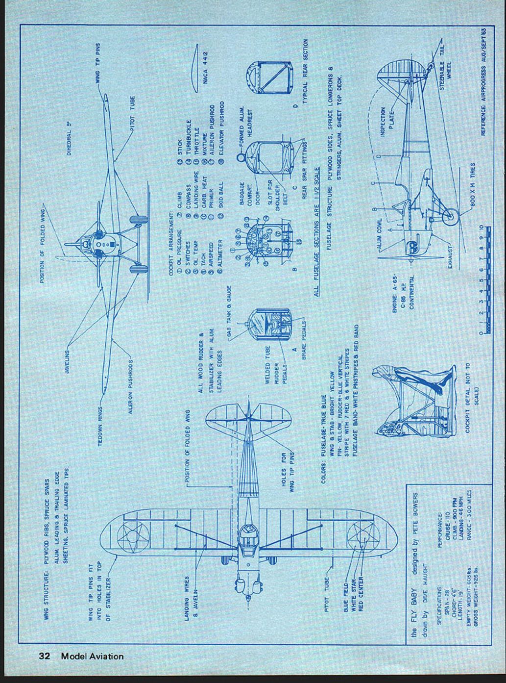
SEE PHOTOS FOR DETAILS POSITION OF FOLDED WING
WING TIP PINS
DIHEDRAL 2°
PITOT TUBE
LANDING WIRES & JAVELIN
WING TIP PINS FIT INTO HOLES IN TOP OF STABILIZER
HOLES FOR WING TIP PINS
WELDED TUBE RUDDER & PEDALS
BRAKE PEDALS
WELDED TUBE RUDDER & PEDALS (see detail)
SKID BALL
NACA 4412
TYPICAL REAR SECTION
ALL FUSELAGE SECTIONS ARE 1/2 SCALE
TAILWHEEL
EXHAUST
ALUM. COWL
800 X 4 TIRES
COCKPIT DETAIL (scale)
BAGGAGE DOOR
BRAKE PEDALS
WELDED TUBE RUDDER & PEDALS
POSITION OF FOLDED WING (plan view)
LANDING WIRES & JAVELIN
WING TIP PINS FIT INTO HOLES
WING STRUCTURE: PLYWOOD RIBS, SPRUCE SPARS, TRAILING EDGE SHEETING, SPRUCE LAMINATED TIPS
(Instrument cluster and cockpit arrangement shown — see drawings)
SPECIFICATIONS
the FLY BABY designed by PETE BOWERS drawn by DAVE HAUGH
SPECIFICATIONS
ENGINE: A-65, C-85 CONTINENTAL
CRUISE: 90 MPH
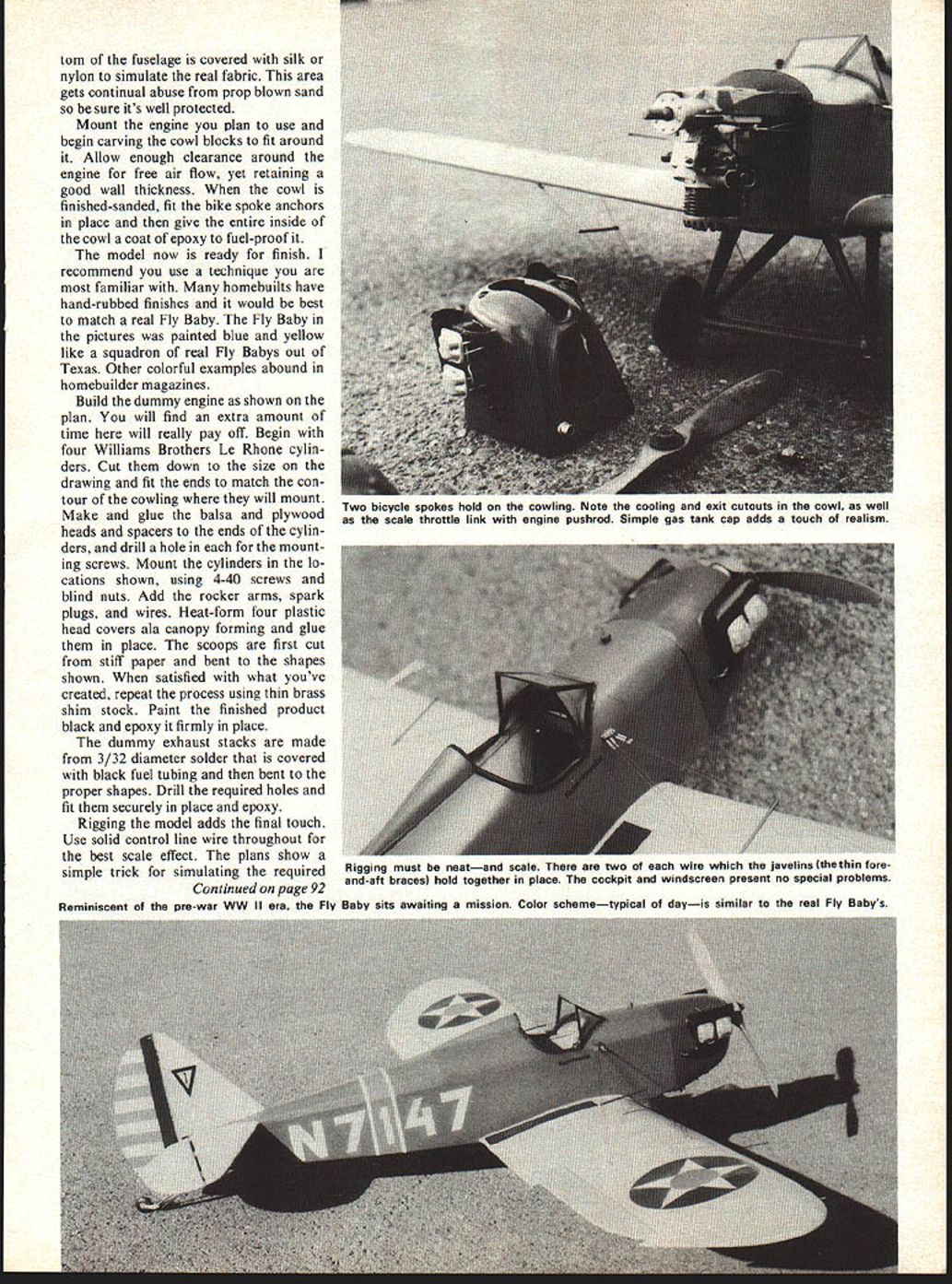
RANGE: 300 MILES Bottom of the fuselage is covered with silk or nylon to simulate the real fabric. This area gets continual abuse from prop‑blown sand so be sure it's well protected.
Mount the engine you plan to use and begin carving the cowl blocks to fit around it. Allow enough clearance around the engine for free air flow, yet retaining a good wall thickness. When the cowl is finished‑sanded, fit the bike‑spoke anchors in place and then give the entire inside of the cowl a coat of epoxy to fuel‑proof it.
The model now is ready for finish. I recommend you use a technique you are most familiar with. Many homebuilts have hand‑rubbed finishes and it would be best to match a real Fly Baby. The Fly Baby in the pictures was painted blue and yellow like a squadron of real Fly Babys out of Texas. Other colorful examples abound in homebuilder magazines.
Build the dummy engine as shown on the plan. You will find an extra amount of time here will really pay off. Begin with four Williams Brothers Le Rhone cylinders. Cut them down to the size on the drawing and fit the ends to match the contour of the cowling where they will mount. Make and glue the balsa and plywood heads and spacers to the ends of the cylinders, and drill a hole in each for the mounting screws. Mount the cylinders in the locations shown, using 4‑40 screws and blind nuts. Add the rocker arms, spark plugs, and wires. Heat‑form four plastic head covers ala canopy forming and glue them in place. The scoops are first cut from stiff paper and bent to the shapes shown. When satisfied with what you've created, repeat the process using thin brass shim stock. Paint the finished product black and epoxy it firmly in place.
The dummy exhaust stacks are made from 3/32" diameter solder that is covered with black fuel tubing and then bent to the proper shapes. Drill the required holes and fit them securely in place and epoxy.
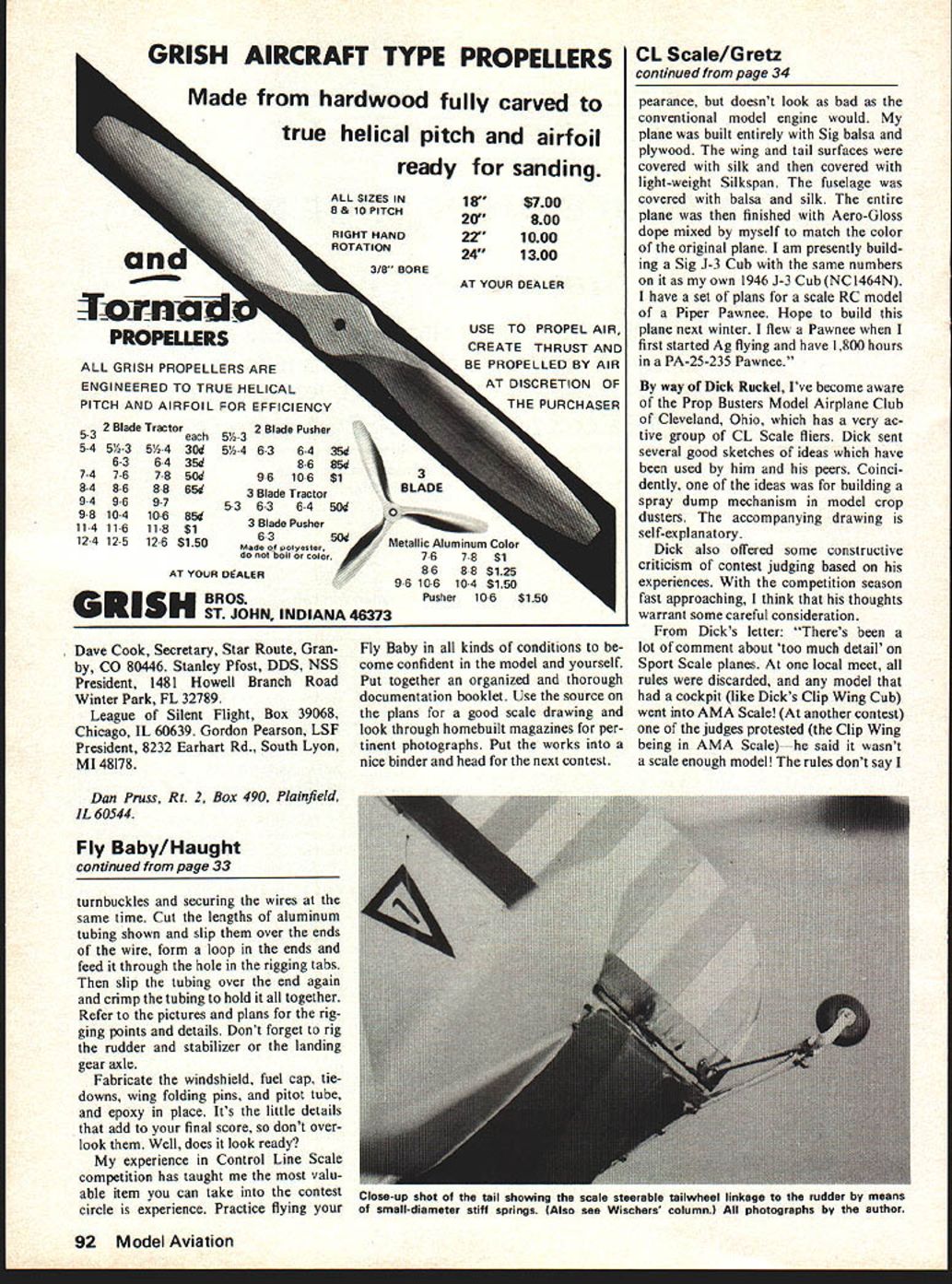
Rigging the model adds the final touch. Use solid control line wire throughout for the best scale effect. The plans show a simple trick for simulating the required turnbuckles and securing the wires at the same time. Cut the lengths of aluminum tubing shown and slip them over the ends of the wire, form a loop in the ends and feed it through the hole in the rigging tabs. Then slip the tubing over the end again and crimp the tubing to hold it all together. Refer to the pictures and plans for the rigging points and details. Don't forget to rig the rudder and stabilizer or the landing gear axle.
Fabricate the windshield, fuel cap, tie‑downs, wing folding pins, and pitot tube, and epoxy in place. It's the little details that add to your final score, so don't overlook them. Well, does it look ready?
My experience in Control Line Scale competition has taught me the most valuable item you can take into the contest circle is experience. Practice flying your Fly Baby in all kinds of conditions to become confident in the model and yourself. Put together an organized and thorough documentation booklet. Use the source on the plans for a good scale drawing and look through homebuilt magazines for pertinent photographs. Put the works into a nice binder and head for the next contest.
Transcribed from original scans by AI. Minor OCR errors may remain.

