
Brace Yourself
Larry Kruse
How well an aircraft flies and how long it lasts are directly proportional to the strength-to-weight ratio built into it. Lightweight, strong planes generally fly better and last longer than heavy, weak ones. (I realize there are those who may wonder how I know this, considering I've only had experience with the latter; however, I'm going to forge ahead anyway.)
There are several good tips for building both lightweight and strong ships that can be used by even the beginning modeler. Proper stress compensation and gusseting can add durability to a model without a corresponding weight penalty.
Gussets
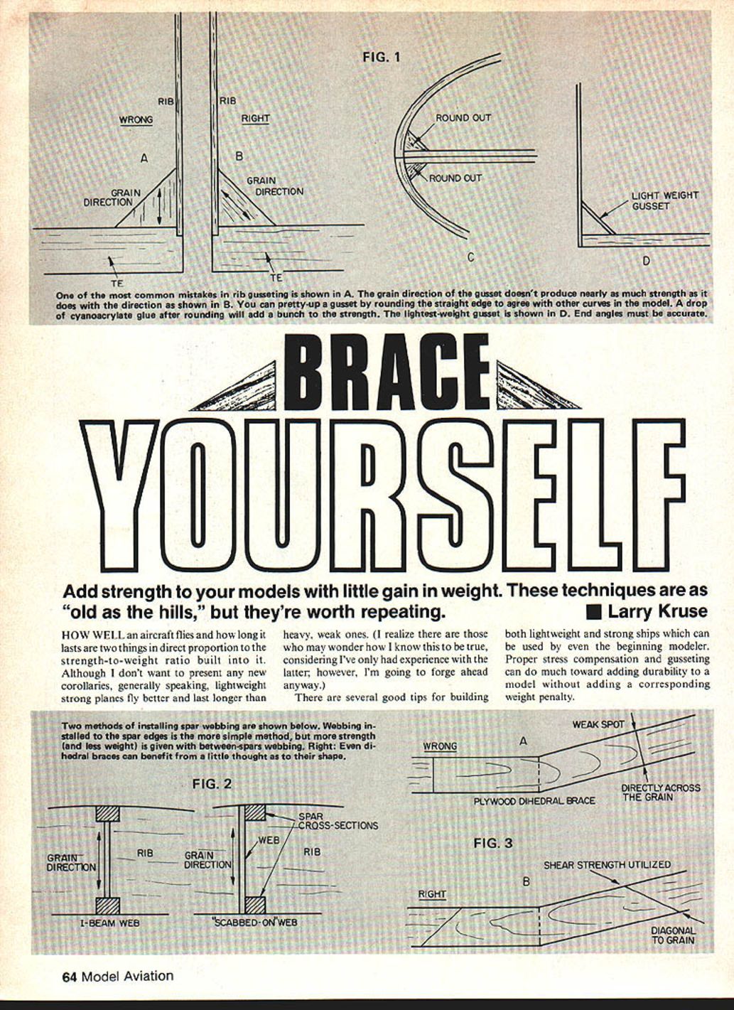
One of the most common construction mistakes is shown in Fig. 1(A). Gussets cut with the grain running vertical to the base of the triangle add strength in only one direction. Gussets cut like Fig. 1(B) add lateral, longitudinal, and torsional strength.
Gussets for scale ships can be handled a bit differently for the sake of appearance in areas where the harsh straight line of a triangular gusset might interrupt the flow of a curved tail surface. Once the gusset is installed, it can be rounded with a jeweler's file or sandpaper wrapped around a small dowel to conform to the curvature of the structure it supports. A drop or two of Hot Stuff on the rounded-out gusset will give it all the strength it requires; see Fig. 1(C).
Figure 1(D) shows another style of gusset useful on ships where light structural weight is of paramount importance. Take pains to assure the gusset is cut at correct angles on both ends, since there isn't a lot of gluing surface available.
Spar Webbing
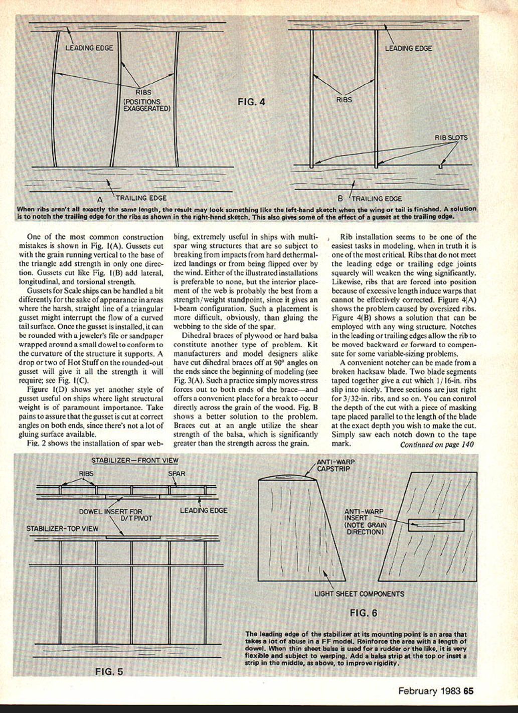
Fig. 2 shows the installation of spar webbing, extremely useful in ships with multi-spar wing structures that are subject to breaking from impacts (hard dethermalized landings) or from being flipped over by the wind. Either of the illustrated installations is preferable to none, but the interior placement of the web is probably best from a strength/weight standpoint, since it gives an I-beam configuration. Such placement is more difficult, obviously, than gluing the webbing to the side of the spar.
Dihedral Braces
Dihedral braces of plywood or hard balsa constitute another type of problem. Kit manufacturers and model designers have cut dihedral braces off at 90° on the ends since the beginning of modeling (see Fig. 3(A)). Such a practice simply moves stress forces out to both ends of the brace—and offers a convenient place for a break to occur directly across the grain of the wood.
Fig. 3(B) shows a better solution. Braces cut at an angle utilize the shear strength of the balsa, which is significantly greater than the strength across the grain.
Rib Installation
Rib installation seems one of the easiest tasks in modeling, when in truth it is one of the most critical. Ribs that do not meet the leading-edge or trailing-edge joints squarely will weaken the wing significantly. Likewise, ribs forced into position because of excessive length induce warps that cannot be effectively corrected. Figure 4(A) shows the problem caused by oversized ribs.
Figure 4(B) shows a solution that can be employed with any wing structure. Notches in the leading or trailing edges allow the rib to be moved backward or forward to compensate for variable sizing problems. A convenient notcher can be made from a broken hacksaw blade:
- Tape two blade segments together to give a cut which 1/16-in. ribs slip into nicely.
- Three sections are just right for 3/32-in. ribs, and so on.
- Control the depth of the cut with a piece of masking tape placed parallel to the length of the blade at the exact depth you wish to make the cut. Saw each notch down to the tape mark.
Moving Parts and Wear
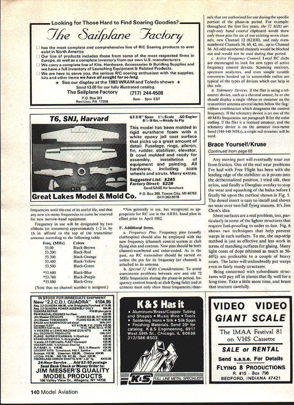
Any moving part will eventually wear out from friction. One real wear problem I've had with Free Flight is the leading edge of the stabilizer as it pivots into the dethermalized position. I tried silk, then nylon, and finally a fiberglass overlay to stop the wear and squashing of the balsa before I finally hit upon the method shown in Fig. 5. The dowel insert is easy to install and showed no wear over two full flying seasons. It's Jim Clem's idea.
Sheet Surfaces and Fuel-Proofing
Sheet surfaces are a real problem, particularly in some of the lighter structures that require fuel-proofing to last. Fig. 6 shows two techniques that help prevent warps in such surfaces. To me, the cap-strip method is just as effective and less work in terms of matching surfaces for gluing.
Many light coats of dope (thinned as much as 50–60%) are preferable to a couple of heavy coats. Heavy coats will undoubtedly put warps even in fairly sturdy structures.
Being concerned with subordinate structures will pay off in planes that fly well for a long time. Take a little more time, and brace that structure carefully.
Transcribed from original scans by AI. Minor OCR errors may remain.

