
Bristol Boxkite
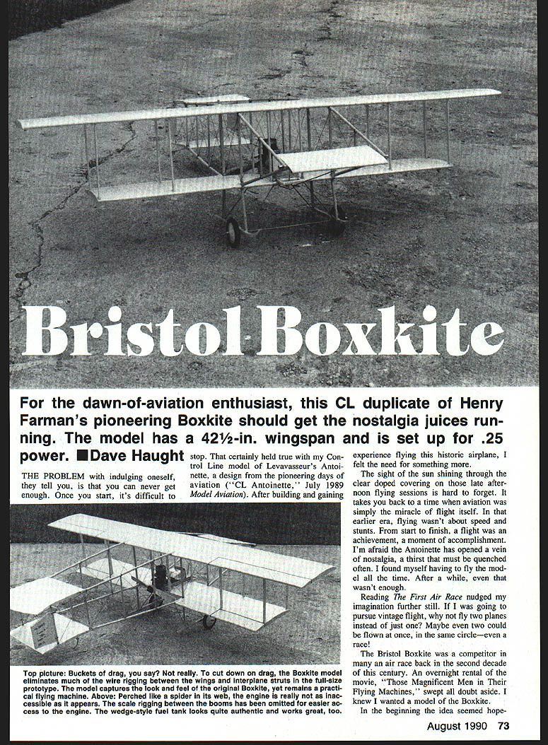
For the dawn-of-aviation enthusiast, this control-line (CL) duplicate of Henry Farman's pioneering Boxkite should get the nostalgia juices running. The model has a 42-1/2 in. wingspan and is set up for .25 power.
Introduction
After building and flying a CL Antoinette (Model Aviation, July 1989), I wanted something else—something that captured the early romance of flight. The sight of sunlight shining through clear-doped covering during late-afternoon flying sessions takes you back to a time when aviation itself was the miracle. Reading The First Air Race and seeing the movie Those Magnificent Men in Their Flying Machines cemented the idea: I wanted a Farman Boxkite.
The Boxkite name was loosely applied to many of Henry Farman's early three-surface designs. The Bristol company obtained a license to build the Farman biplane in 1910; more than 70 variations were produced. I chose to design the model around the Fox .25 engine (throttled RC type), matching my Antoinette, and used materials similar to the original—dowels, plywood, wire, and heavy thread.
Specifications
- Wingspan: 42-1/2 in.
- Power: .25 glow engine (throttled)
- Primary materials: dowels, plywood, aluminum tubing, wire, silkspan tissue
Materials and tools (high level)
- 48-in. long straight dowels (select best straight-grained stock)
- 1/8-, 3/16-, and 5/32-in. round files
- 15–30 minute epoxy; CA (cyanoacrylate) for smaller joints
- Plywood gussets and 1/8-in. plywood for engine mount
- 1/4-in. aluminum wire (trailing edge)
- 1/8-in. aluminum tubing (main spar for elevator)
- 1/16-in. sheet (webbing) and 1/16-in. sq. sticks (rudders)
- Heavy thread for wrapping joints
- Silkspan tissue (heavy for wings, lightweight for elevator/stabs)
- Clear dope (several coats)
- 0.020-in. music wire for rigging (optional)
- Standard modeling tools: pins, sanding block, drill, blind nuts, prop and balancing tools
Construction
If you have the vintage-model bug, the following steps will guide you through the Boxkite build. Take your time; precise fitting and strong joints are essential.
Fuselage
- Construct two side frames as nearly identical as possible. Cut two of every part for exact matching. Build each side one at a time as you would a stick fuselage.
- Mate dowel joints precisely. Use the collection of round files to make the joints fit closely. If any part is not right, remake it. Glue each joint with 15- to 30-minute epoxy for strength.
- When one side is finished, cover it with plastic wrap and build the second side directly on top to ensure both sides match.
- Add plywood gussets at the nose and the T fittings at the rear. Install the landing skids.
Stabilizers (including front elevator/canard)
- The stabilizers differ in configuration but are built the same way. Cut out all ribs and file the concave leading edges using a 1/8-in. round file.
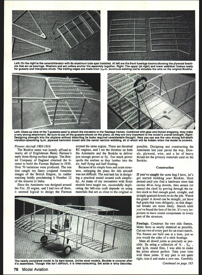
- Notch spar locations and file a notch in each rib's trailing edge to fit the 1/4-in. aluminum wire trailing edge.
- Pin leading edge dowels and spars over the plan, then pin ribs and trailing edge. Use CA for these assemblies; use epoxy for major joints.
- Install 1/4-in. gussets where required—position them carefully so they won't show through the covering.
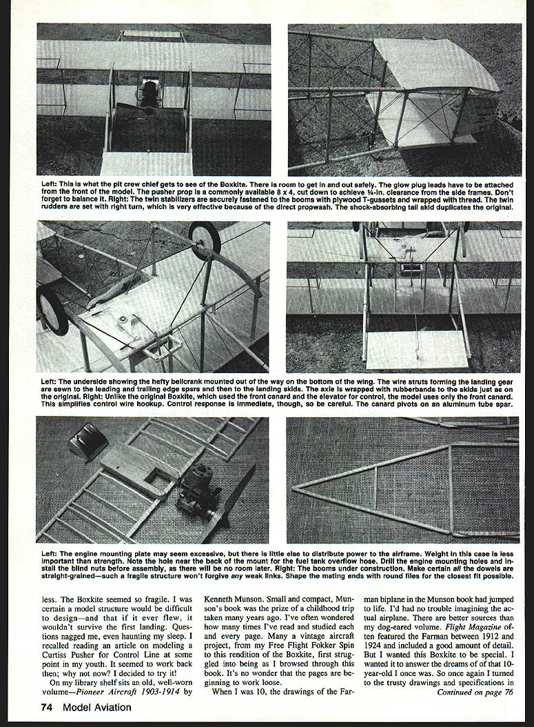
- The front elevator (canard) does the primary flying on the model. On the full-size Boxkite the front elevator was coupled to the rear stabilizers by cables; on the model this coupling is unnecessary.
- For the elevator: cut ribs, file concave leading and trailing edges, and cut the plywood control-horn mount. The main spar is 1/8-in. aluminum tubing; slip ribs over the spar and pin them on the plan before gluing. The aluminum spar should extend about 1/2 in. beyond the end ribs. Install the control horn plate flush with the bottom of the elevator.
Wings
- Cut out all wing parts; there are many ribs—stack-cutting 15 at a time speeds the work. Modify a few standard sizes for spacer ribs at the center.
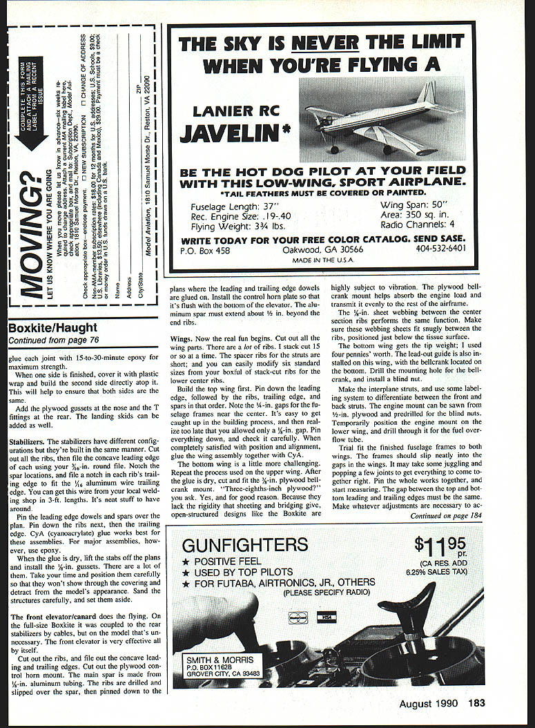
- Build the top wing first: pin down the leading edge, ribs, trailing edge, and spars in that order. Note the 1/4-in. gaps for the nacelle frames near the center—verify gap size before gluing. When satisfied, glue the assembly with CA.
- Build the bottom wing the same way. After glue is dry, cut and fit the 1/8-in. plywood bellcrank mount. Use 3/8-in. plywood where noted: open-structure designs like the Boxkite are subject to vibration, and the plywood bellcrank mount helps transmit engine loads evenly.
- Install 1/16-in. sheet webbing between center-section ribs to add stiffness; fit snugly just below the tissue surface.
- Add tip weight to the bottom wing (the prototype used the equivalent of four pennies).
- Install lead-out guide and locate the bellcrank on the bottom wing; drill the mounting hole and install a blind nut.
- Make interplane struts and mark front vs. rear struts to avoid confusion.
- Saw the engine mount from 1/8-in. plywood and predrill for blind nuts. Temporarily position the mount on the lower wing and drill through for the fuel overflow tube.
- Trial-fit the fuselage frames to both wings. Frames should slip into the gaps; some light jiggling may be required. Pin the assembly together and check alignment carefully. The gap between top and bottom leading edges—and between trailing edges—must be equal along the wings' length. When alignment is correct, epoxy the wings to the frames.
- Block the model on the bench so the wings are level. Block up the lower stabilizer so it matches the rear fuselage frames and glue it in place on the T fittings.
- Cut dowel rudder posts to a length that keeps the upper stabilizer parallel with the lower one, then glue on the upper stabilizer.
- Add interplane struts into the slots left by the spacer ribs; before final gluing, recheck equal gaps between wings.
- Install the engine mount at 0° thrust.
- Bend landing-gear brace wires and sew them to the wing leading and trailing edges with heavy thread. Wrap the T fittings joining the stabilizers to strengthen the joints and give an authentic appearance. Wrap landing skid-to-wire joints as well.
- Make the twin rudders from 1/16-in. square sticks, sand edges round, and prepare for covering.
Covering
- Most models are covered before final assembly, but with this open-structure Boxkite, cover after major assembly. Set aside a block of time.
- Apply four coats of clear dope to the entire model, sanding between coats.
- Use heavy silkspan for the wings and lightweight silkspan for the elevator and stabilizers.
- Cut tissue strips wide enough to fit between struts chordwise. Cover the bottom wing first, working from the trailing edge forward. Then cover the top wing, working from the trailing edge toward the leading edge.
- Cover the elevator simply; for the stabilizers cover the bottoms first, then the tops. Apply extra dope to the tissue at the stabilizer trailing edges before covering the top. Press tissue seams together and smooth with a wet brush. When dry, trim and sand lightly.
- Finish with four or five coats of clear dope (or until the tissue shows a slight sheen and looks slightly transparent).
- Make tail-skid parts and epoxy them to the leading edges of the stabilizers.
- Install the front elevator by opening the front fuselage frames to slip the tubing spar into the holes drilled in the frames; slip a washer between frame and root rib. Add wheel collars that secure the elevator and install the control horn on the bottom of the elevator.
- Bend and install the pushrod and lead-outs. Check controls for freedom of movement and correct any binding.
- Install vintage-style wheels on the axle and run the axle through to the skids.
Rigging
- Rigging greatly enhances authenticity. I used 0.020-in. music wire for rigging, but other materials will work.
- Study photographs and rig accordingly. Keep rigging tight and tidy—CA it as you go, pulling it taut to maintain a clean appearance.
- Make sure rigging is secure and symmetrical on both sides.
Flying
- Final checks before flight:
- Correct any warps in surfaces.
- Trim an 8 x 4 prop to fit between the frames with at least 1/4 in. clearance at the closest point in its arc. Balance the prop by carving/sanding the heavier blade if necessary.
- Balance the model slightly nose-heavy for the first flight. The front elevator is sensitive; the model may porpoise if not properly balanced.
- Practice the starting procedure before fueling up. Work through glow plug clip removal and needle valve adjustments.
- If you feel excessive vibration or see loose parts after starting the engine, shut down and repair.
- The Boxkite is designed to fly—enjoy the experience and the nostalgia.
Closing
The Boxkite is a rewarding build that captures the look and feel of pioneering aircraft. Kenneth Munson's Pioneer Aircraft 1903–1914 and contemporary photos are excellent references for additional pioneer designs to try. Dream on—and happy building and flying!
Transcribed from original scans by AI. Minor OCR errors may remain.

