
Bristol Scout
Many, many years ahead of its time in 1916 the British Bristol Monoplane fighter makes a distinctive good-flying project for single-channel RC—or you may wish to modify it for more controls with the Cannon RC system.
IMAGINE A FULLY streamlined monoplane fighter with a maximum speed in the vicinity of 130 mph, designed and available in 1916, and not being put into production. And this was not some freakish design but a very practical and well-engineered aircraft, built by an established manufacturer.
Exactly why the Bristol Monoplane didn't see service on the Western Front is still a mystery. True, there was still some prejudice against monoplanes in this time period, resulting from much earlier flying accidents, but several monoplanes did make it to the combat zone, and were successful. The Bristol Monoplane, however, did not. A token quantity was made, shipped to the Middle East, and there saw some action, but in general no real use was made of the potent M1.
One of the excuses for not producing the Bristol was that the landing speed was too high for the small Western Front aerodromes, but this does seem more of an excuse than a serious defect in the design. Whatever the real reasons were, the fact remains that the aircraft did not see action in a serious way, and why remains only one of the many mysteries of Government thinking in WW I. For those interested in greater historical details, a list of references can be found at the end of this article.
This is the second Bristol Monoplane I've built, the first one being a free-flight version powered by an aged diesel and about fifty percent bigger than the model shown here. This turned out to be an excellent flier, and also a world traveller. Constructed in California, and first flown in Sepulveda Basin, it was then taken to England on one of my longer trips back there and flown casually for most of one summer. On one of its flights (let's make just one more flight type), it flew away in the dark, and was next heard of in the local Police Station, after being picked off some irate citizen's roof.
However, that's another model, and another time, so let's get back to the current version.
Construction
Construction can be seen to be quite conventional, and the following notes discuss some of the building details and sequences.
Landing Gear: The building sequence I prefer is one where all the items are made in the order that they are required, so that the completion of one part isn't interrupted by having to stop work and make another subsection first, if you see what I mean. Anyhow, this system leads us to start with—guess what—the undercarriage. This has to be installed about half way through the fuselage construction, so it's a good idea to get it ready now.
The main legs are made from a single piece of wire, and the plans show the true shape of this before the final bends are put into it. Try to make this basic frame as accurately as possible; after this, carefully bend down each leg equally, so that the model will sit correctly when it's completed. When the frame has been bent satisfactorily the axle can be cut and attached. This is lashed into the V of the leg with fine copper wire, then soldered in place. The wheels can either be attached now, or after the model has been finished and painted. I usually do the latter, as my spray painting tends to cover everything, and everybody.
The completed undercarriage can now be put on one side while we get on with the next item, which is the fuselage.
Fuselage: This begins by selecting about half dozen good quality lengths of 1/8-sq. for the basic fuselage box. Now spread the plans on the building board, and cover the fuselage section with a sheet of wax paper. Pin down two of these 1/8-sq. strips for the upper and lower longerons, then cement all the 1/8-sq. spacers into place. When this frame is dry, remove it from the board, and make another one exactly the same. While this latter fuselage side is setting up the 1/8-ply firewall is cut out and drilled for the engine mounting bolts. When both fuselage frames are available they should be sanded very lightly, then joined together with 1/8-sq. spacers and the firewall.
Putting this on one side for a moment, we'll prepare the under-carriage unit for installation. Bind, using carpet thread, two strips of 1/8 x 1/4 to the wire, smearing cement all over this combination so as to hold the U/C unit firmly in place, then install it into the fuselage, as shown on the plan.
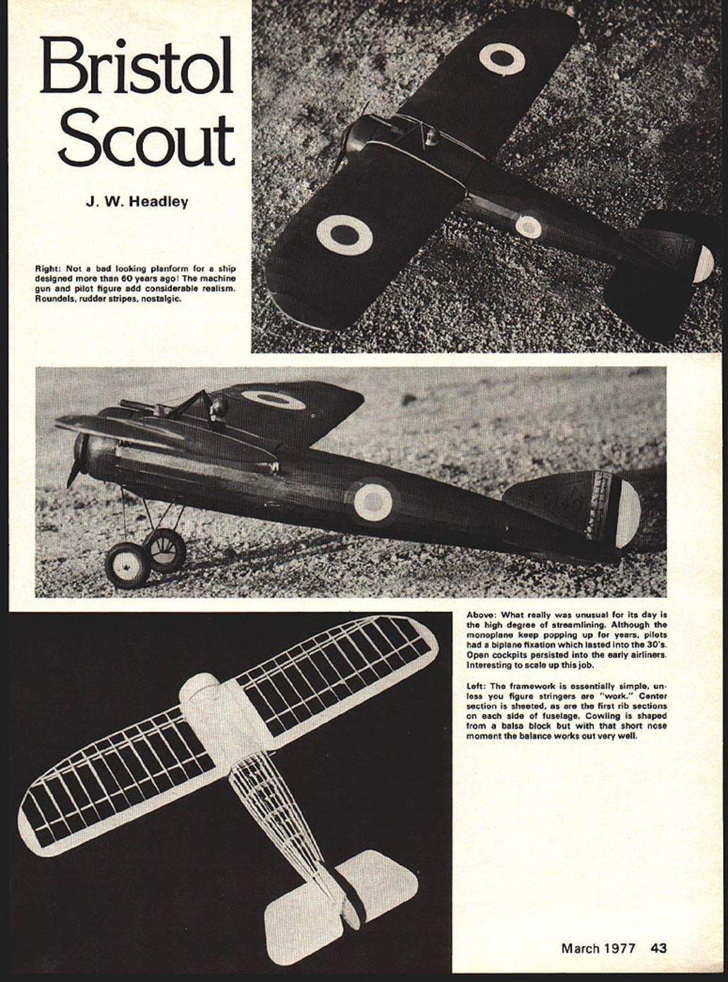
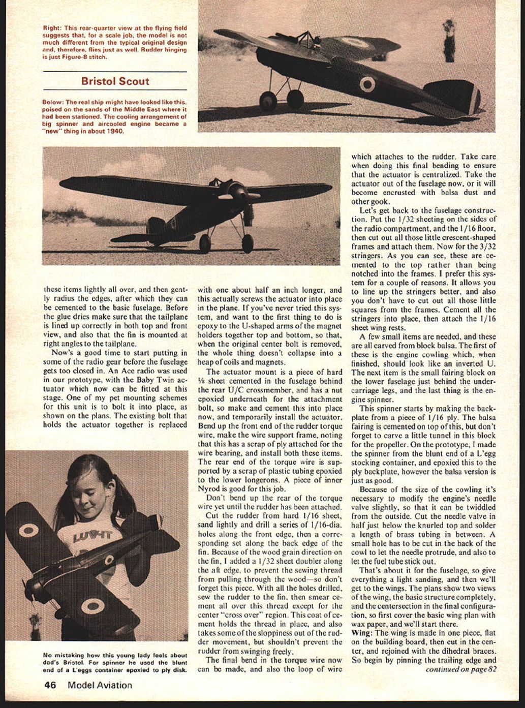
Select a good flat sheet of 1/16 balsa, and cut out the tailplane and the fin. Sand Right: Not a bad looking planform for a ship designed more than 60 years ago! The machine gun and pilot figure add considerable realism. Roundels, rudder stripes, nostalgic.
Above: What really was unusual for its day is the high degree of streamlining. Although the monoplane kept popping up for years, pilots had a biplane fixation which lasted into the 30s. Open cockpits persisted into the early airliners. Interesting to scale up this job.
Left: The framework is essentially simple, unless you figure stringers are "work." Center section is sheeted, as are the first rib sections on each side of the fuselage. Cowling is shaped from a balsa block but with that short nose moment the balance works out very well.
Construction
Construction can be seen to be quite conventional. The following notes discuss some building details and sequences.
Landing gear. The building sequence I prefer has items made in the order required for completion so that work is not interrupted to make another sub-assembly. First see what I mean. Anyhow, the system leads us to start with — guess what — the undercarriage. It is installed about half way through fuselage construction, so it is a good idea to get ready now. The main legs are made from a single piece of wire; the plans show the true shape before the final bends are put in. Try to make the basic frame as accurately as possible. After carefully bending the legs down equally, the model will sit correctly when the completed frame has been assembled. The axle can be attached or lashed to the V-leg with fine copper wire and soldered in place. Wheels can either be attached now or after the model has been finished and painted — usually the latter.
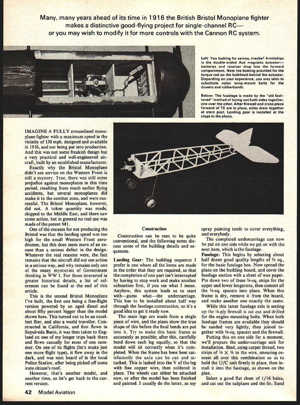
Servos and control installation. Mount servos amidships as shown on the plan. The double-ended Ace magnetic actuator, batteries and receiver fit into the forward compartment. Note the bearing provided on the torque-rod bulkhead behind the actuator. Depending on experience and preference you may wish to substitute nylon wing-mount bolts, dowels or rubber-bands for the wing fittings.
Fuselage. The fuselage is built in the old-fashioned method, laying out both sides together over each other. With the firewall and the forward cross-piece in place, draw the sides together at the stern post. With the landing gear installed at this stage, spray painting tends to cover everything, so complete the undercarriage before proceeding to the next item — the fuselage assembly proper.
Begin by selecting about half a dozen good quality lengths of 5/32-in. sq. for the basic fuselage box. Spread the plans on the building board and cover the fuselage section with wax paper. Pin down two 1/8-in. sq. strips for the upper and lower longerons and cement 1/8-in. sq. spacers in place. Assemble the frame dry, remove it from the board and make another exactly the same for the other fuselage side. With both fuselage sides completed, sand them very lightly, then join them together using 1/8-in. sq. spacers and the firewall. Cut out and drill the 1/8-ply firewall for the engine mounting bolts before final assembly.
With one fuselage side on one side for a moment, prepare the undercarriage unit for installation. Bind, using carpet thread, two strips of 1/8 x 1/4 to the wire, smearing cement over the combination so as to hold the U/C unit firmly in place, then install it into the fuselage as shown on the plan. Select a good flat sheet of 1/16-in. balsa and cut out the tailplane and the fin. Sand these parts to shape.
The framework is essentially simple unless you consider stringers "work." The center section is sheeted, as are the first rib sections on each side of the fuselage. The cowling is shaped from a balsa block but with that short nose moment the balance works out very well.
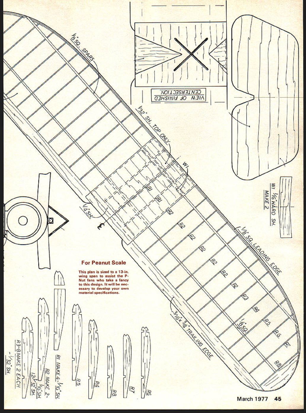
For Peanut Scale
This plan is sized to a 13-in. wing span to assist the P-Nut fans who take a fancy to this design. It will be necessary to develop your own material specifications. These items lightly all over, and then gently radius the edges, after which they can be cemented to the basic fuselage. Before the glue dries make sure that the tailplane is lined up correctly in both top and front view, and also that the fin is mounted at right angles to the tailplane.
Now's a good time to start putting in some of the radio gear before the fuselage gets too closed in. An Ace radio was used in our prototype, with the Baby Twin actuator which now can be fitted at this stage. One of my pet mounting schemes for this unit is to bolt it into place, as shown on the plans. The existing bolt that holds the actuator together is replaced with one about half an inch longer, and this actually screws the actuator into place in the plane. If you've never tried this system, and want to, the first thing to do is epoxy to the U-shaped arms of the magnet holders together top and bottom, so that, when the original center bolt is removed, the whole thing doesn't collapse into a heap of coils and magnets.
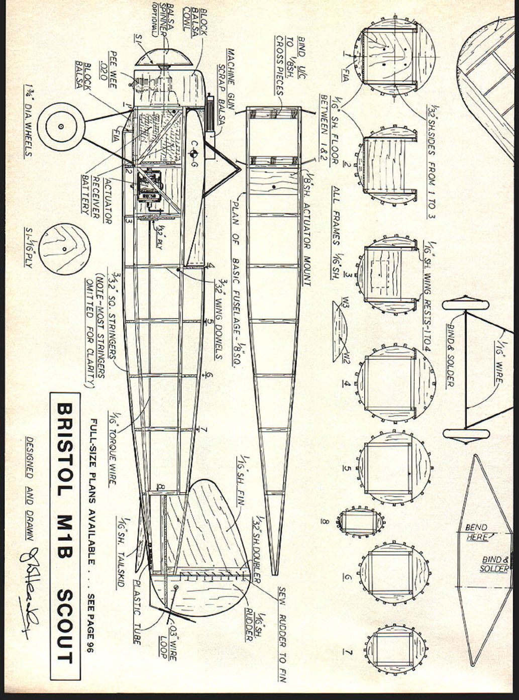
The actuator mount is a piece of hard 1/8-in. sheet cemented in the fuselage behind the rear U/C crossmember, and has a nut epoxied under neath for the attachment bolt, so make and cement this into place now, and temporarily install the actuator. Bend up the front end of the rudder torque wire, make the wire support frame, noting that this has a scrap of ply attached for the wire bearing, and install both these items. The rear end of the torque wire is supported by a scrap of plastic tubing epoxied to the lower longerons. A piece of inner Nyrod is good for this job.
Don't bend up the rear of the torque wire yet until the rudder has been attached.
Cut the rudder from hard 1/16-in. sheet, sand lightly and drill a series of 1/16-dia. holes along the front edge, then a corresponding set along the back edge of the fin. Because of the wood grain direction on the fin, I added a 1/32-in. sheet doubler along the aft edge, to prevent the sewing thread from pulling through the wood—so don't forget this piece. With all the holes drilled, sew the rudder to the fin, then smear cement all over this thread except for the center "cross over" region. This coat of cement holds the thread in place, and also takes some of the sloppiness out of the rudder movement, but shouldn't prevent the rudder from swinging freely.
The final bend in the torque wire now can be made, and also the loop of wire which attaches to the rudder. Take care when doing this final bending to ensure that the actuator is centralized. Take the actuator out of the fuselage now, or it will become encrusted with balsa dust and other gook.
Let's get back to the fuselage construction. Put the 1/32 sheeting on the sides of the radio compartment, and the 1/16 floor, then cut out all those little crescent-shaped frames and attach them. Now for the 3/32 stringers. As you can see, these are cemented to the top rather than being notched into the frames. I prefer this system for a couple of reasons. It allows you to line up the stringers better, and also you don't have to cut out all those little squares from the frames. Cement all the stringers into place, then attach the 1/16 sheet wing rests.
A few small items are needed, and these are all carved from block balsa. The first of these is the engine cowling which, when finished, should look like an inverted U. The next item is the small fairing block on the lower fuselage just behind the undercarriage legs, and the last thing is the engine spinner.
This spinner starts by making the backplate from a piece of 1/16-in. ply. The balsa fairing is cemented on top of this, but don't forget to carve a little tunnel in this block for the propeller. On the prototype, I made the spinner from the blunt end of a L'egg stocking container, and epoxied this to the ply backplate, however the balsa version is just as good.
Because of the size of the cowling it's necessary to modify the engine's needle valve slightly, so that it can be twiddled from the outside. Cut the needle valve in half just below the knurled top and solder a length of brass tubing in between. A small hole has to be cut in the back of the cowl to let the needle protrude, and also to let the fuel tube stick out.
That's about it for the fuselage, so give everything a light sanding, and then we'll get to the wings. The plans show two views of the wing, the basic structure completely, and the centersection in the final configuration, so first cover the basic wing plan with wax paper, and we'll start there.
Wing: The wing is made in one piece, flat on the building board, then cut in the center, and rejoined with the dihedral braces. So begin by pinning the trailing edge and
Bristol Scout/Headley
the lower 1/8-sq. spars down to the board, and cement into place all the 1/32 sheet ribs, and then the upper 1/8-sq. spar.
The only tricky item is next, which is bending the 1/8-sq. leading edge. Before trying to add this piece, soak it in hot water to make the bending easier. As an alternate, the highly curved portion of the leading edge can be cut from 1/8 sheet.
When all the glue is dry, cut the wing in the center and glue back together, using the dihedral braces W1. A scrap of 1/4 sheet is used to reinforce the trailing edge joint. Add all the 1/16 sheet ribs, then the 1/32 sheeting on the top of the centersection. This completes the basic wing construction.
When the fuselage is complete put the wing into place, and then make and fit pieces W2 and W3. Finish off the wing by gluing into place the 1/32" sheeting over these items.
Covering: All the open framework is covered with medium-weight tissue, which is then given a couple of coats of clear dope. The tail surfaces are not covered, but just given a sealing coat of clear dope, after which a final light sanding can be made. The complete model is then sprayed with the final color coating.
Additional trim is a compromise between scale accuracy, and flight performance. Including all the correct bracing wires, etc. makes an attractive looking model, but certainly increases the drag, and hence reduces the flyability. So now is the time to decide how much detail to put on. On the original model, I included the cabane structure, and the bracing wires on the top of the wing (using black thread). The only other details, apart from the roundels, were drawn in place with India ink.
Color Schemes: For those whose inclinations are more towards flying than finishing, there is a perfectly authentic color scheme available. The real prototypes were all finished with clear dope, and the only markings were the usual roundels, and a black serial number on the fin, A5319 being typical. I must admit that I was tempted to use this, but somehow it doesn't seem right to have a World War I aircraft that wasn't painted green, so I chose the production aircraft finish, which was the standard khaki-green, with black serials on the fin. C4950 was typical. The only problem I found with this scheme was that it gave almost perfect camouflage on my local flying field, making the model difficult to spot, and impossible to photograph. A set of photos taken there turned out to be totally useless, as one couldn't tell where the model stopped and the grass began.
Installation: We've already covered the installation of the actuator, and the torque wire has been installed, so all that remains is to put in the battery and receiver, and they fit in a compartment just ahead of the actuator. A small 1/16" sheet frame is required here to isolate these items from the actuator. When all the radio pieces have been installed check that the torque wire is still free to oscillate, that the rudder hinges haven't frozen up, and most important of all, that the rudder moves in the correct direction when commanded.
Flying: Now for the interesting bit, off to the flying field. My attitude toward single-channel work is that it's actually free flying without all the running around (well, it's my opinion), i.e., the model needs to be trimmed for flying on its own, and the radio is there to stop it flying away. So as we only have rudder control the pitch stability has to be built into the model, and this is the first thing to do at the field.
By varying the wing incidence and the C.G. location slightly, make sure that the flight path isn't just a series of stalls, which are usually followed by a heart-rendering sound of compacting balsa. Once you've got this sorted out, the only other adjustment is to set the rudder throw; don't make it either too sensitive, or too insensitive.
From this point on it's up to you, so good luck, and as a friend of mine always says, enjoy!
References
There's not an awful lot written about the Bristol; the books I used follow:
- British Aeroplanes 1914-1918, by J. M. Bruce
- Bristol Aircraft Since 1910, by C. H. Barnes
- Warplanes of the First World War, Fighters, Vol. I, by J. M. Bruce
If you're interested in a detailed model of a particular plane, a good selection of photographs can be found in these books. They show the minor variations between types, a window here, a cut-out there, etc.
Color details can be found in Aircraft Camouflage and Markings 1907-1954 by Bruce Robertson, and this is the source I used when decorating my prototype.
Transcribed from original scans by AI. Minor OCR errors may remain.

