
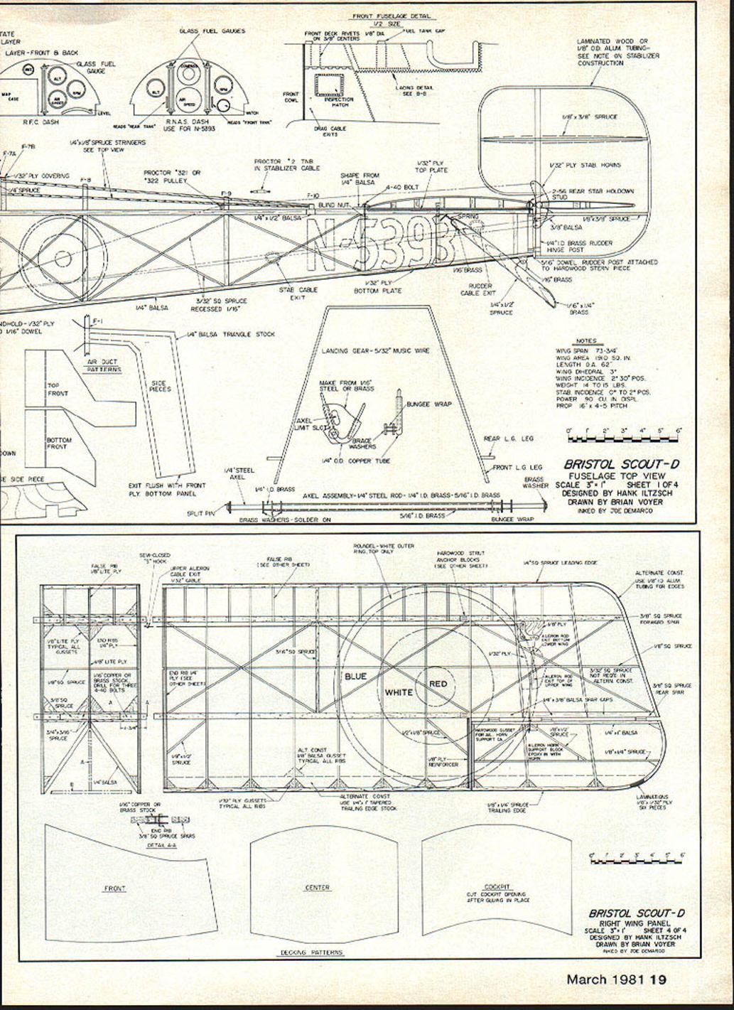
Bristol Scout Model-D
Part 1. • Hank Iltzsch Color pictures by Ernst Mausolf
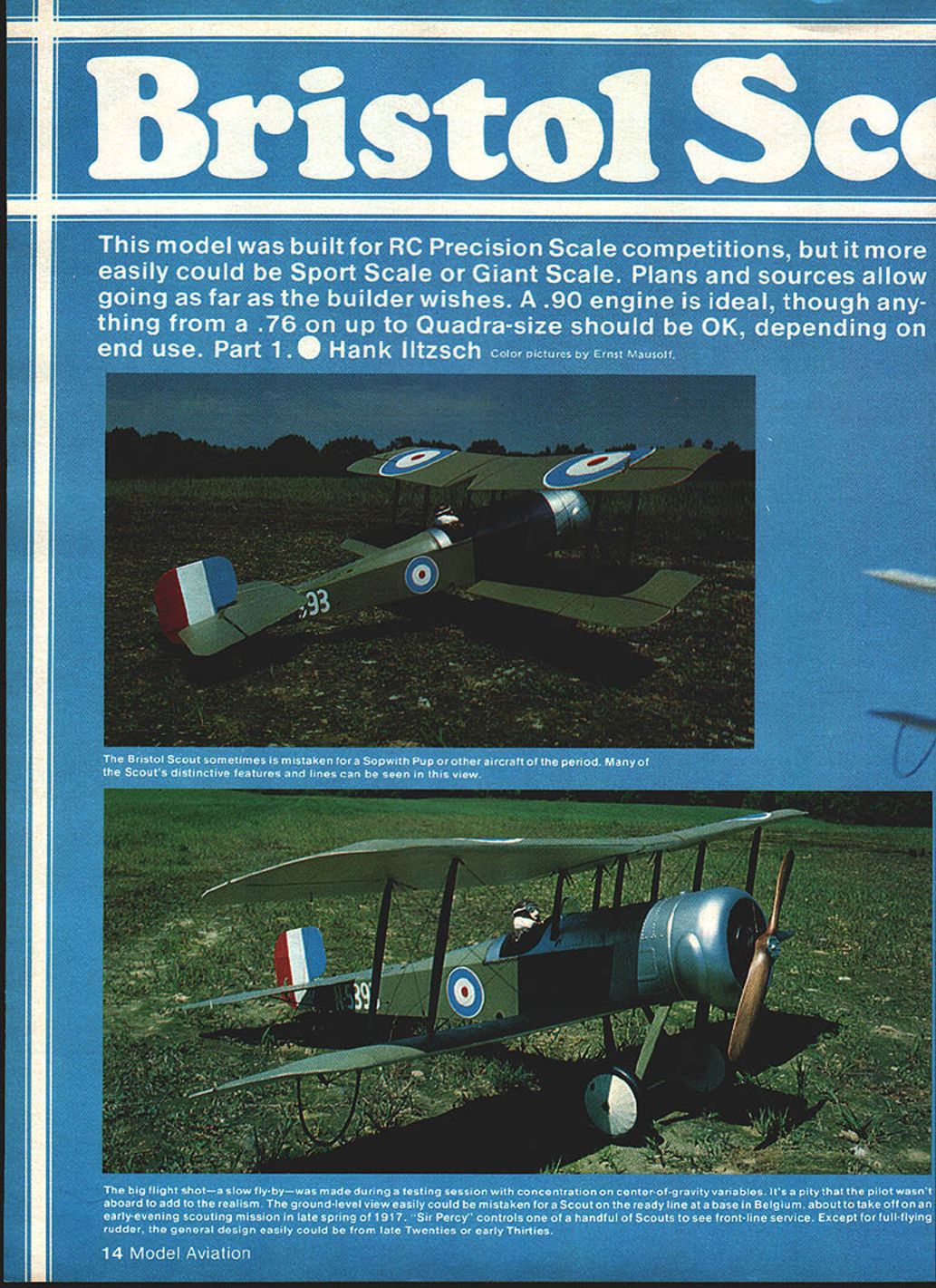
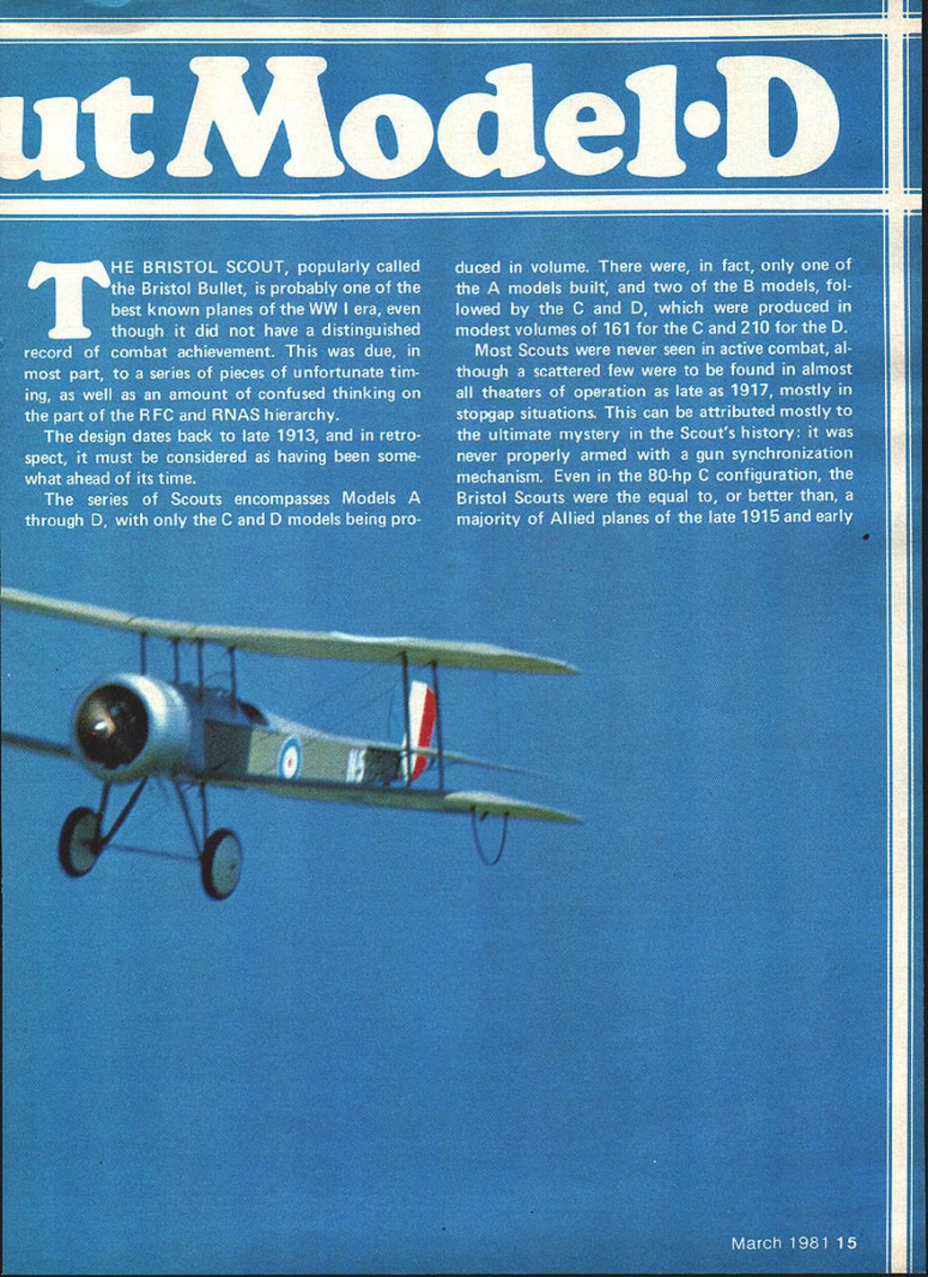
The Bristol Scout, popularly called the Bristol Bullet, is probably one of the best-known planes of the WW I era, even though it did not have a distinguished record of combat achievement. This was due, in most part, to a series of pieces of unfortunate timing, as well as some confused thinking on the part of the RFC and RNAS hierarchy.
The design dates back to late 1913, and in retrospect it must be considered somewhat ahead of its time. The series of Scouts encompasses Models A through D, with only the C and D models produced in volume. There was only one A model built and two B models, followed by modest production runs of 161 C models and 210 D models.
Most Scouts were never seen in active combat, although scattered examples were to be found in almost all theaters of operation as late as 1917, mostly in stopgap situations. This is attributable mostly to the ultimate mystery in the Scout's history: it was never properly armed with a gun synchronization mechanism. Even in the 80-hp C configuration, the Bristol Scouts were equal to or better than a majority of Allied planes of late 1915 and early 1916 in most areas of performance.
As with most planes of this period, the Bristol Scouts experienced a number of running changes in various configurations. The serious modeler must select a precise serial number and chase down the variables that might apply to that particular plane. Although C and D models generally looked similar, there could be several areas of variation at any time, not the least of which were the differences between RFC and RNAS planes. Other areas of difference include rudder and elevator configurations, ailerons, and cowlings for different engines. With careful research and appropriate adjustments, any C or D model Scout can be constructed from the plans and information provided in this article.
The reason for my selection of this particular Scout D—RNAS serial number 5393—was my access to three excellent pictures showing good detail on this plane in an issue of Air Power magazine.
From stand-off project to Precision Scale
The model did not start out to be a Precision Scale project. I had previously designed and built a large biplane, ultimately named the "Great Waldo Bipe," which was published elsewhere. That was purely a sport plane. I then decided to build a stand-off or look-alike plane that would generally fit the parameters of the Bipe. After study and sorting I felt the Bristol Scout at 3 in. = 1 ft. scale would fit the bill.
While gathering information on Bristol Scouts I could not find any indication that the aircraft, although well known and much modeled, had ever been done for Precision Scale. Unbeknownst to me, a group of highly motivated and ingenious guys in Olean, N.Y., known as the STARS, were working in parallel and eventually produced a fleet of magnificent stand-off 3-in.-scale Scouts.
My project turned toward all-out scale when I learned that Leo Opdycke, publisher of the marvelous journal World War I Aeroplanes, was beginning construction of a full-scale replica of the D and had original factory drawings. With that kind of information it would not have been fitting to attempt anything other than a full-blown Precision Scale project. Anyone interested in WW I aircraft should write to Leo and get on his mailing list; there is no subscription charge.
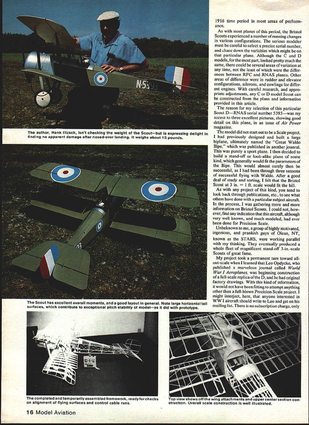
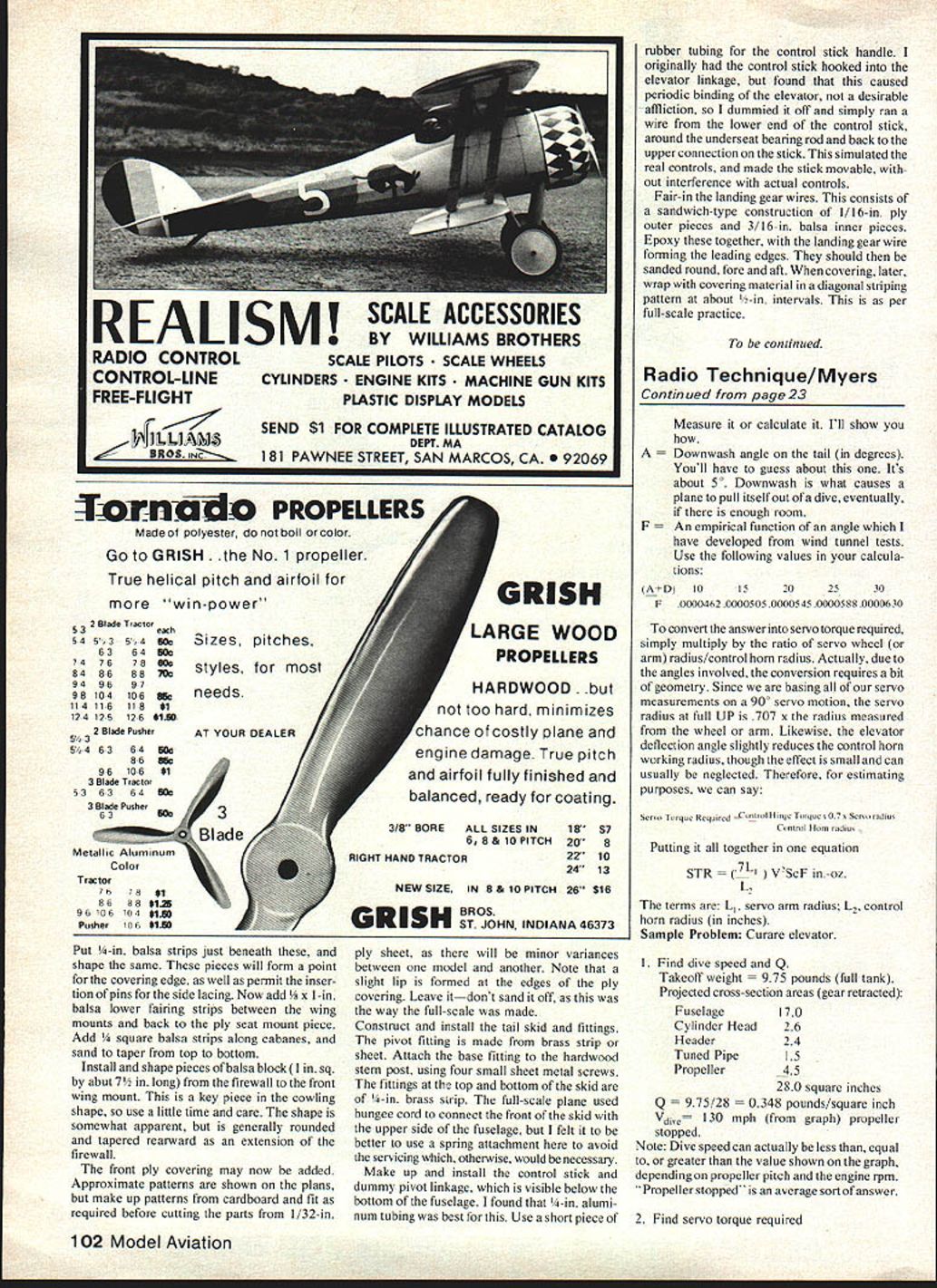
Model Aviation author Hank Iltzsch isn't checking the weight of the Scout in the photos, but expresses delight at finding no apparent damage after a nosed-over landing. The model weighs about 15 lb. The Scout has excellent overall moments and good flying characteristics. Note: the large horizontal tail surfaces contribute to exceptional pitch stability in the model, as did the prototype.
When completed, temporarily assemble the framework for alignment of flying surfaces and control cable runs. Overall construction is well illustrated.
Personal note on the project
I had never attempted anything of this magnitude before and plunged into the project without consulting an experienced scratch-Scale builder. If I had, I am sure the project might have been terminated and the plane would not have seen the light of day.
Although biplanes in general, and WW I planes especially, were my favorite subjects, I had only a vague comprehension of what was involved. While building a second plane to lock in construction details and make desirable modifications, I would occasionally stand back from the original and marvel that I had accomplished it.
It was only through the encouragement of friends—Leo Opdycke in particular—and my wife's enduring patience that it came to pass. Although I hope that by the time this is published the second plane will be flying, I feel a third or fourth plane will be required to fully and correctly do this wonderful aircraft. As Dave Platt put it, "You never finish a Scale plane; you just stop working on it."
The airfoil saga
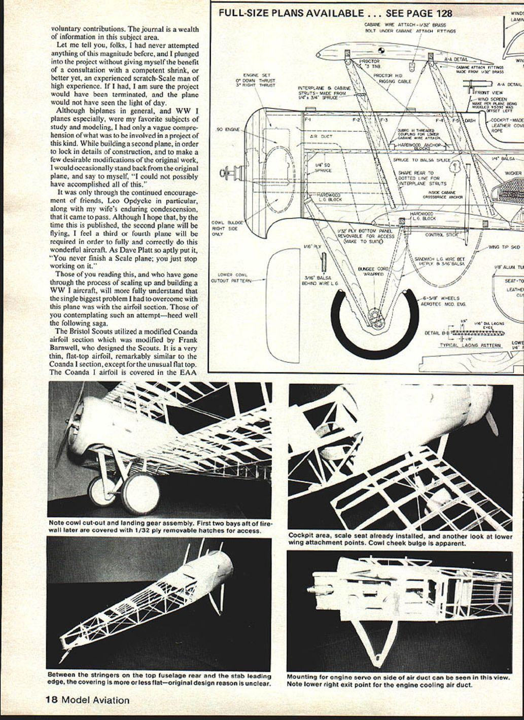
The single biggest problem I had to overcome was the airfoil section. The Bristol Scouts used a modified Coandă airfoil section, modified by Frank Barnwell, who designed the Scouts. It is a very thin, flat-top airfoil, remarkably similar to the Coandă I section except for the unusual flat top. Data on Coandă and other airfoils is covered in the EAA handbook on airfoil sections, which is a wealth of information.
From that data it is apparent that the Coandă I was not a very good airfoil. What the flattening of the top does—Barnwell's modification—would be speculative, as no data apparently exists on it. Unfortunately, this information was uncovered only after completion of the original plane and the onset of problems that were later proved to be directly related to the unusual wing airfoil.
I had assumed that, in quarter-scale size, performance would be comparable to the full-scale plane since Reynolds numbers at the larger model scale are generally more favorable. By all reports the full-scale plane was a sweetheart of a flier, so I duplicated the airfoil section faithfully.
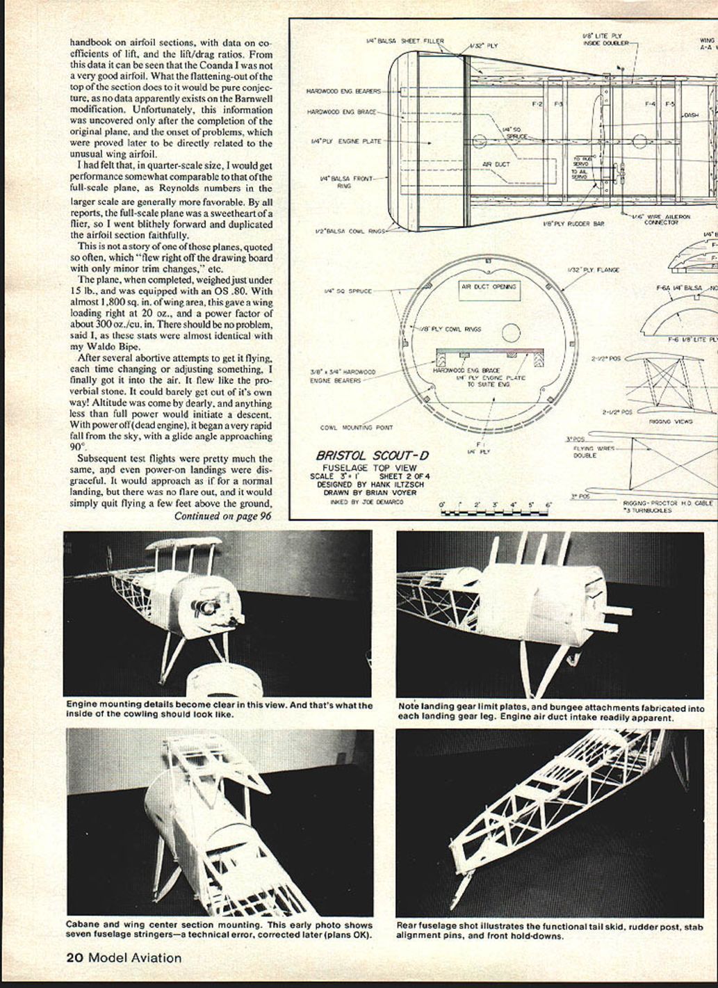
This is not one of those planes that "flew right off the drawing board with only minor trim changes." The completed model weighed just under 15 lb and was equipped with an OS .80. With almost 1,800 sq. in. of wing area, this gave a wing loading right at 20 oz/sq ft (note: original stats were given in oz. per sq. ft.) and a power factor of about 300 oz./cu. in. I expected no problem—these stats were almost identical with my Waldo Bipe.
After several abortive attempts to get it flying, each time changing or adjusting something, I finally got it into the air. It flew like a proverbial stone. It could barely get out of its own way. Anything less than full power initiated a descent. With the engine off, it entered a very rapid fall with a glide angle approaching vertical. Power-on landings were disgraceful: no flare, and it would simply quit flying a few feet above the ground and thump down on the gear, bending the axles.
I tended to blame CG placement and a deficiency of power, so I installed a Profi .76 (which had performed about 20% better than the OS .80 in my Waldo Bipe) and experimented with CG—all to no avail. Performance was still lousy. Much head-scratching and analysis finally laid blame on the airfoil; the flight deficiencies pointed clearly to that cause.
You biplane builders know that building two wings is about twice the work of a single wing, but I concluded the airfoil needed to be modified or changed, which meant constructing a whole new set of wings. I didn't want to deviate from the scale undercamber, so I searched for a section that would be aesthetically acceptable and give the required performance.
I decided to use the ISA-96 section from the EAA handbook. On paper it looked very good. The ISA-96 compares favorably with the Clark Y; the Clark Y is a good lifting section, though slightly high on drag.
New wings and flight tests
To get new wings built quickly, I used the alternate wing construction method shown on the plans. This uses 1/8-in. balsa ribs rather than the spruce-capped 1/32-in. ply ribs of the original, and aluminum wing and aileron tips in place of laminated wood tips. With this method, construction of the new wings went rapidly.
On test day I was only slightly apprehensive despite previous disappointments. Fellow members of the South Shore Radio Control Club were set to witness another hairy flight. Only a few knew of the wing change, and it would have taken an astute observer to detect the difference between the new and old wings.
The plane performed as I had hoped. Takeoff and climb-out were scale-like. After a few trimming laps, I set up for a landing approach, cut the throttle, and the plane began a nice low-angle glide. While still holding a bit of power I flared and it settled in for a gentle landing. The only sour note was a graceful nose-over on roll-out due to premature release of up-elevator, a common tail-dragger error.
Subsequent flights were made and the only major change afterward was installation of a freshly broken-in Webra .91 in place of the Profi .76. The combination then proved reliable and dozens of flights were made as I prepared for entry in the Rhinebeck WW I Jamboree.
The plans show both the true-scale and alternate methods of wing construction. Choose the type or combination that best suits you. On the second plane (the third set of wings), I used scale ply built-up ribs and a spruce trailing edge but retained 1/8-in. aluminum tubing tips, which have proven satisfactory. Instead of breaking a wood wing tip in a minor accident, the tubing often just bends and can be reshaped readily.
Power recommendation
I feel that a .90-size engine is a must for Precision Scale. If you do not want to compete in AMA Precision Scale, you can use larger engines—as proven by the STARS with their Quadra- and Roper-powered stand-off models. Larger engines require some modification of the firewall and deepening of the cowl. I have several larger engines and intend to put one in the original plane after completion of the second plane, which I will use for Precision Scale competition.
The plane can be flown with an OS .80 or Profi .76, but the .90-size gives the edge needed to overcome the large frontal-area drag while retaining reserve power for emergencies. Best prop size has proven to be about 16 in. diameter with 4½- to 5-in. pitch.
Construction, for the most part, is straightforward. I attempted to duplicate original construction within normal modeling limits while keeping the model transportable in something less than a moving van. The plane has gone to the field many times in a VW Rabbit, often accompanied by other small planes and necessary gear. As with any Scale plane, the small things take the most time while adding the greatest authenticity. The following guide will serve the knowledgeable builder.
Note: All photos accompanying this text are of the original plane. There have been upgrades and changes during the course of building the second plane; these changes are incorporated into the plans and construction details. If discrepancies are noted, the plans contain updated material relative to improved authenticity and better construction methods. Using these changes will result in a slightly more favorable weight factor, as the original was marginally under the AMA limit for Precision Scale.
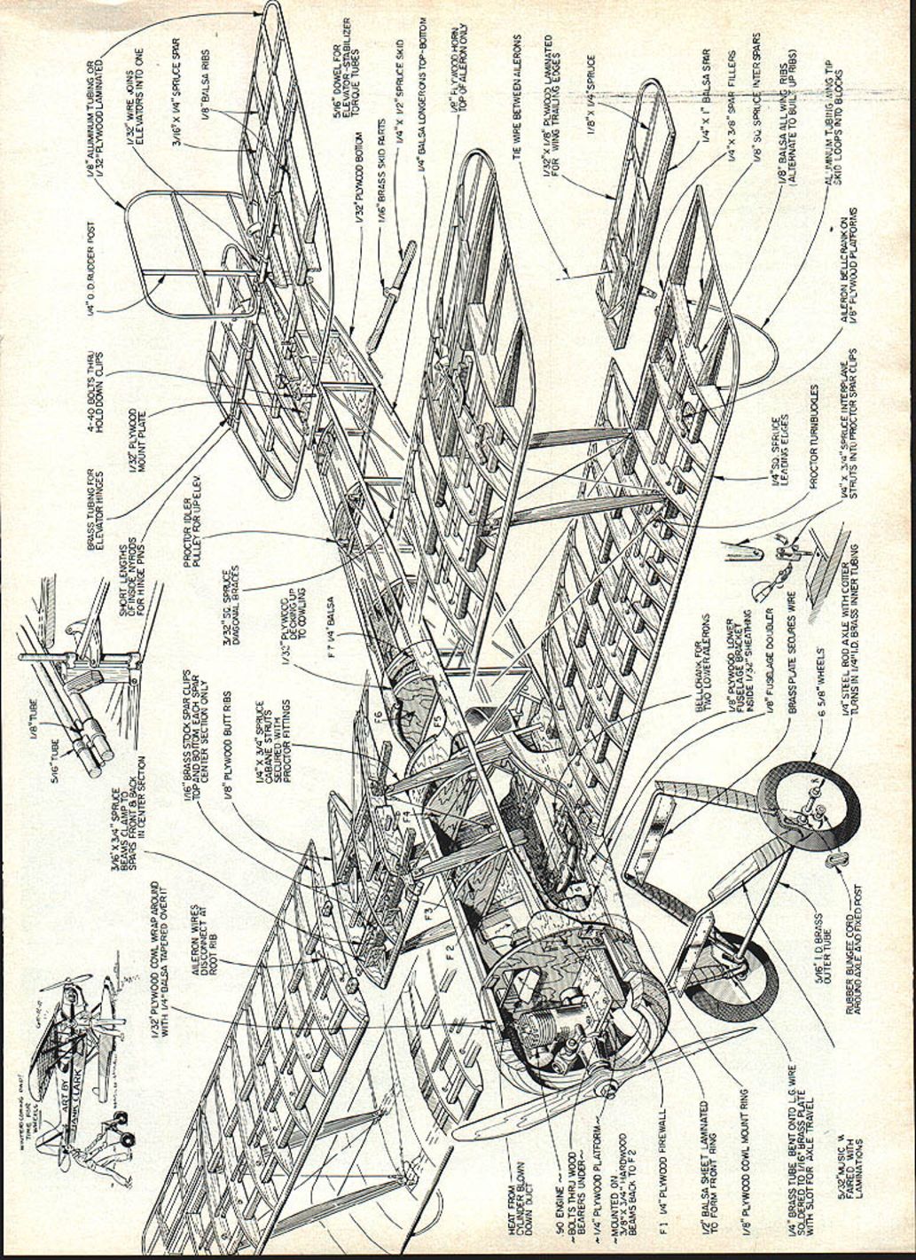
Construction and material notes (as shown on the plans)
- 1/32-in. plywood cowl wraparound with 1/4-in. balsa tapered over it.
- Aileron wires disconnect at root rib (F2).
- Brass tubing for elevator hinges.
- 3/16 x 3/4-in. spruce beams; clamp to short lengths.
- Struts front and back made from inside Nyrod (nylon rod).
- 1/8-in. plywood in center section for hinge pin/mount plate.
- Proctor idler pulley for up elevator; 1/16-in. brass stock.
- Spar clips top and bottom on each spar center section only; 1/8-in. plywood bolt ribs.
- 1/4 x 1 3/4-in. spruce cabane struts secured with Proctor fittings.
- 3/32-in. square spruce diagonal braces.
- 1/32-in. plywood decking up to cowling.
- Fit 1/4-in. balsa shapes where shown.
- 4-40 bolts through rudder post/appropriate wood fittings.
- 1/8-in. aluminum tubing or hold-down clips.
- 1/32-in. plywood laminated pieces; 1/32-in. wire joins elevators into one.
- 3/16 x 1/4-in. spruce spar; 1/8-in. balsa ribs (for alternate wing construction).
- 5/16-in. dowel for elevator–stabilizer connection.
- 1/32-in. plywood bottom torque tubes; 1/16-in. brass skid parts.
- 1/4 x 1 1/2-in. spruce skid; 1/4-in. balsa longerons top-beam.
- 1/8-in. plywood horn at top of aileron only.
- Engine bolts through wood; bearers under 1/4-in. plywood platform mounted on 3/8–3/4-in. hardwood beams back to F2.
- 1/4-in. plywood firewall (see plans for exact thickness and detail).
- Tie wire between ailerons; 1/32 x 1/8-in. plywood laminated for wing trailing edges.
- 1/8 x 1 1/4-in. spruce; 1/2-in. balsa sheet laminated to form front ring.
- 1/8-in. plywood cowl mount ring.
- 1/4-in. brass tube bent onto low wire, soldered to 1/16-in. brass plate with slot for axle travel.
- 5/32-in. music wire faired with laminations.
- Brass cutter tube, rubber bungee cord, axle and fixed bellcrank for two lower ailerons.
- Various spruce fillers and internal structure as shown on plans; fuselage bracket inside 1/8-in. sheathing; 1/8-in. sq. spruce internal structure.
(See the plans for additional dimensions, rib spacing, lamination schedules, and assembly order.)
Fuselage
First, construct the fuselage sides. Use epoxy on all joints. Laminate 1/8-in. lite-ply doublers to the inside of each fuselage side with epoxy. After carefully marking their positions on the inside of the front doublers, epoxy on the motor mount beams.
Cut two each front and rear cabane pieces, using either shaped Proctor pieces or make them from 3/8 x 1/4-in. spruce. Mark the position of cabanes on the outside of the fuselage sides, and after cutting out a piece of the upper 1/8-in. spruce longeron to accommodate them, epoxy the cabanes in position on the outside of the fuselage. Use slow-setting epoxy and carefully check alignment so both sides are identical.
Epoxy firewall, F-2 through F-5, and the two wing seats in place, making sure of squareness in the top view. With the fuselage upside-down over the top view and with the cabanes hanging over the edge of your workbench, epoxy in the shaped stern post. Add top formers F-6 through F-11 along with their bottom pieces. Add rear cross pieces and the 1/32-in. ply stern plates, top and bottom.
Add aft 1/4 x 1/8-in. spruce stringers and the short pieces of 1/4-in. spruce between F-6 and F-7. Add 1/8 x 1/4-in. spruce inside and 1/8 x 3/8-in. balsa on top of the main fuselage longeron between F-5 and F-6. Sand the balsa piece to the contour of the formers.
Construct the cylinder-head air duct per drawings. This may be fitted and installed now or fitted later when more convenient. Cut and fit servo tray bearers. Keep the servos as far forward as possible and to the right of the fuselage to clear the cylinder-head air duct. Mount three servos here: rudder, elevator and ailerons. Provide a mount on the side of the air duct for the throttle servo.
Construct and fit the rudder bar and aileron connector bellcrank. An excellent base can be made from molded nylon bearings similar to those used on firewalls for tricycle gear.
Bend the landing-gear wires from 5/32-in. tempered wire per the detail on the plans. Fabricate a landing-gear guide plate from thin sheet steel or brass. Use a piece of 1/8-in. O.D. copper tubing to form the bottom U-shaped piece at the junction of the front and rear landing-gear wires. The guide plate conforms to this shape and goes on the outside of the copper connector.
When making up the wire gear, leave sufficient bend for the oleo bungee retainers. Make these too long and cut off after adding the copper washers and copper tubing spacer. Hold the whole assembly in alignment on a separate block of wood, check all dimensions, then silver-solder all parts well. Don't forget to add the copper washers and the spacer to the bungee connectors.
Install the landing-gear blocks into the fuselage, then fit and add the wire gear assembly. Recheck alignment and fasten in place with 3/16-in. plywood plates and 5/16-in. metal screws; this will allow easier removal later if the landing gear is bent.
Add the front 1/4-in. spruce stringers. Note that the front pieces splay out to the firewall edge. Add small pieces of scrap around the point where these pieces meet the firewall.
Install the rear seat brace of 1/4-in. spruce between the two 1/32-in. ply plates on the outside of the fuselage. Below this mount a piece of 5/32-in. aluminum tubing inside a piece of outer Nyrod material. This is a bearing surface for all of the cables for the rudder and elevator. On the full-scale plane small pulleys were mounted here for each of the wires. The builder may elect to follow full-scale practice for added effect, but alignment of the control wires will be more critical and difficult.
Mount spruce blocks at the inside corners of each cabane to accommodate anchors for the cabane side-brace wires. Sand to the contour of the adjoining formers F-2 and F-3. These blocks will be covered by the front ply covering. Fix into place the inside cabane brace-wire connections; these may be small hook eyes or some convenient strong connection. As shown on the rigging diagram, these wires cross just above the front covering; placement can be best ascertained by running a straightedge from the top of each cabane brace to a point on the opposite inside fuselage to ensure the wires cross above, not below, the covering.
Add outside 1/8-in. spruce fairing strips from the firewall to former F-6 and taper into the sides. Put 1/4-in. balsa strips just beneath these and shape the same. These pieces will form a point for the covering edge and permit insertion of pins for the side lacing. Add 1/8 x 1-in. balsa lower fairing strips between the wing mounts and back to the ply seat mount piece. Add 1/8-in. square balsa strips along the cabanes and sand to taper from top to bottom.
Install and shape pieces of balsa block (about 1 in. square by 7½ in. long) from the firewall to the front wing mount. This is a key piece in cowl shaping; use a little time and care. The shape is generally rounded and tapered rearward as an extension of the firewall.
The front ply covering may now be added. Approximate patterns are shown on the plans, but make up cardboard patterns and fit as required before cutting parts from 1/32-in. ply, as there will be minor variances between models. Note that a slight lip is formed at the edges of the ply covering—leave it; this was how the full-scale was made.
Construct and install the tail skid and fittings. The pivot fitting is made from brass strap or sheet. Attach the base fitting to the hardwood stern post using four small sheet-metal screws. The fittings at the top and bottom of the skid are of 1/8-in. brass strip. The full-scale plane used bungee cord to connect the front of the skid with the upper side of the fuselage, but I preferred a spring attachment here to avoid servicing.
Make up and install the control stick and dummy pivot linkage, visible below the bottom of the fuselage. I found 1/4-in. aluminum tubing best for this. Use a short piece of rubber tubing for the control-stick handle. I originally had the control stick hooked into the elevator linkage but found it caused periodic elevator binding; I removed that connection and simply ran a wire from the lower end of the control stick around the under-seat bearing rod and back to the upper connection on the stick. This simulates the real controls and makes the stick movable without interfering with actual controls.
Fair-in the landing-gear wires with a sandwich of 1/16-in. ply outer pieces and 3/16-in. balsa inner pieces. Epoxy these together with the landing-gear wire forming the leading edge, then sand round fore and aft. When covering later, wrap with covering material in a diagonal striping pattern at about 1/2-in. intervals per full-scale practice.
To be continued.
Transcribed from original scans by AI. Minor OCR errors may remain.

