
Bristol Scout Model D
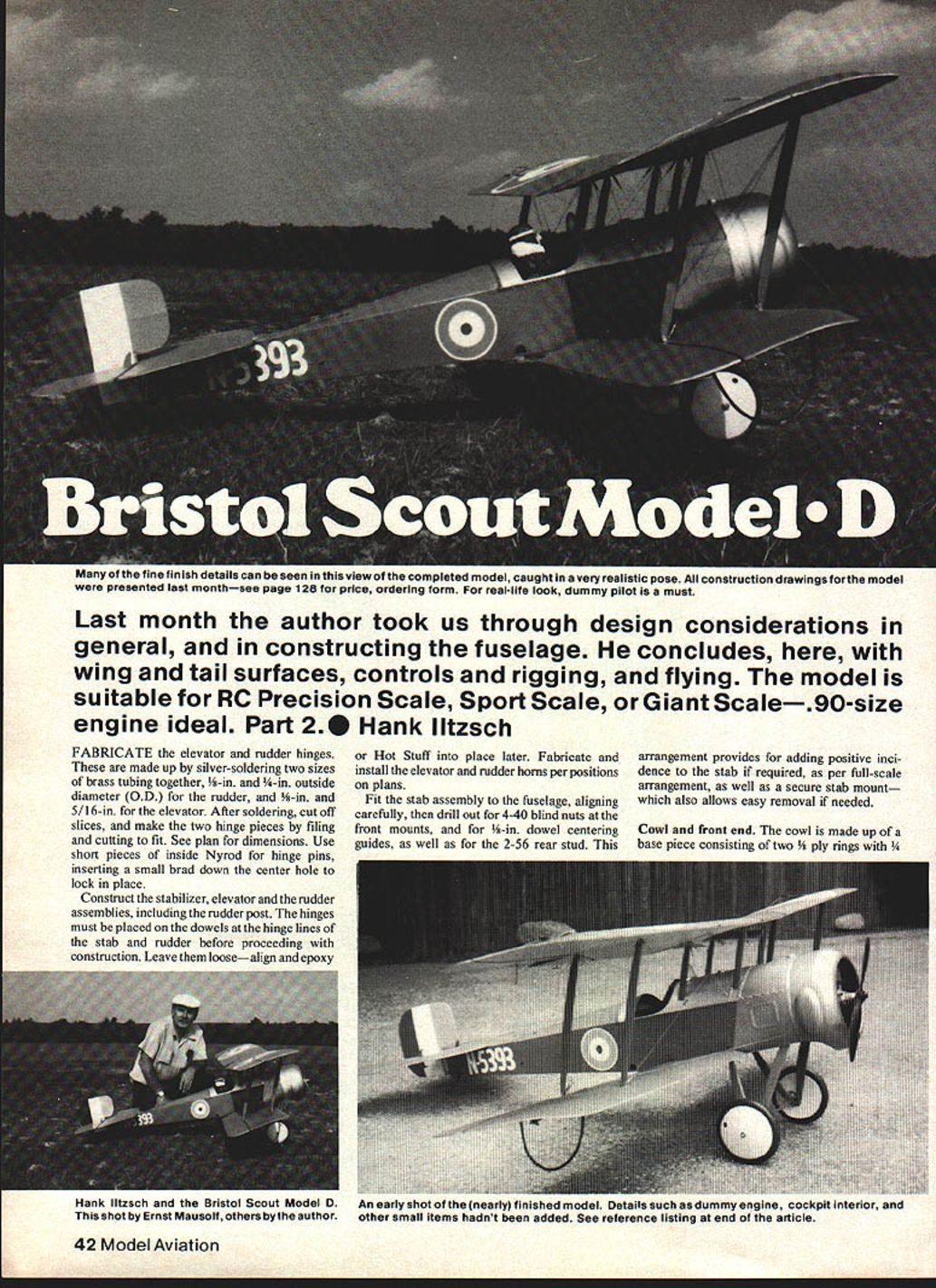
Many of the fine finish details can be seen in this view of the completed model, caught in a very realistic pose. All construction drawings for the model were presented last month—see page 128 for price and ordering form. For a real-life look, a dummy pilot is a must.
Last month the author took us through design considerations in general and in constructing the fuselage. He concludes here with wing and tail surfaces, controls and rigging, and flying. The model is suitable for RC Precision Scale, Sport Scale, or Giant Scale—.90-size engine ideal. Part 2. — Hank Iltzsch
Fabricate the elevator and rudder hinges
Fabricate the elevator and rudder hinges by silver-soldering two sizes of brass tubing together: 5/16-in. and 1/4-in. outside diameter (O.D.) for the rudder, and 3/16-in. and 5/16-in. for the elevator. After soldering, cut off slices and make the two hinge pieces by filing and cutting to fit. See plan for dimensions. Use short pieces of inside Nyrod for hinge pins, inserting a small brad down the center hole to lock them in place.
Stabilizer, elevator and rudder assembly
Construct the stabilizer, elevator and rudder assemblies, including the rudder post. Place the hinges on the dowels at the hinge lines of the stabilizer and rudder before proceeding with construction. Leave the hinges loose—align and epoxy or Hot Stuff into place later. Fabricate and install the elevator and rudder horns per positions shown on the plans.
Fit the stabilizer assembly to the fuselage, aligning carefully. Drill out for 4-40 blind nuts at the front mounts, for 1/4-in. dowel centering guides, and for the 2-56 rear stud. This arrangement provides for adding positive incidence to the stabilizer if required (as per full-scale arrangement), and gives a secure stab mount that also allows easy removal if needed.
Cowl and front end
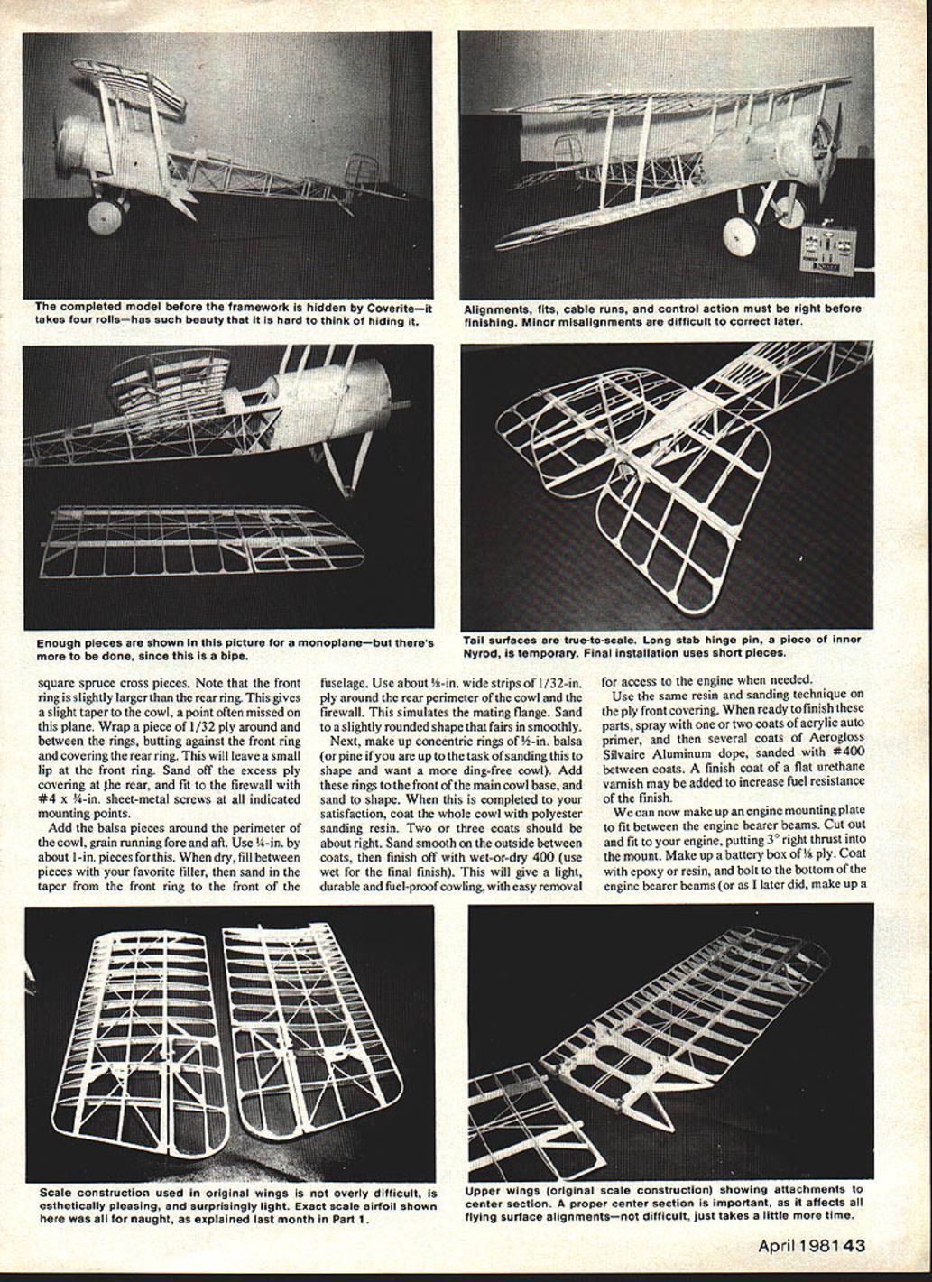
The cowl is made up of a base piece consisting of two 3/8-in. plywood rings with 1/4-in. square spruce cross pieces. Note that the front ring is slightly larger than the rear ring to give a slight taper to the cowl point—often missed on scale models. Wrap a piece of 1/32-in. ply around between the rings, butting against the front ring; do not cover the rear ring completely, which will leave a small lip on the front ring. Sand off any excess ply covering the rear ring and fit the firewall. No. 4 x 1/2-in. sheet-metal screws indicate mounting points.
Add balsa pieces around the perimeter with the grain running fore-and-aft. Use about 5/8-in. by 1-in. pieces. When dry, fill between the pieces with your favorite filler and sand the taper from the front ring to the front of the fuselage. Use about 3/8-in.-wide strips of 1/32-in. ply around the rear perimeter of the cowl and firewall to simulate the mating flange. Sand to a slightly rounded shape and fair smoothly.
Next, make up concentric rings of 1/8-in. balsa (or soft pine if you prefer a more ding-resistant cowl). Stack and sand these rings to shape; you want a ding-free cowl. Add these rings to the front of the main cowl base and sand to complete satisfaction.
Coat the whole cowl with polyester sanding resin—two or three coats should be about right. Sand smooth on the outside between coats and finish off with wet-or-dry 400 grit (use wet for the final finish). This will give a light, durable, fuel-proof cowling and allow easy removal and access to the engine when needed. Use the same resin and sanding technique on the plywood front covering.
Ready the finish parts by spraying one or two coats of acrylic auto primer, followed by several coats of Aerogloss Silvaire Aluminum dope sanded with #400 between coats. A finish coat of flat urethane varnish may be added to increase fuel resistance.
Engine mount and battery box
Make up an engine mounting plate to fit between the engine bearer beams. Cut out and fit to your engine, putting 3° right thrust into the mount. Make up a battery box of 1/8-in. plywood; coat it with epoxy or resin and bolt it to the bottom of the engine bearer beams.
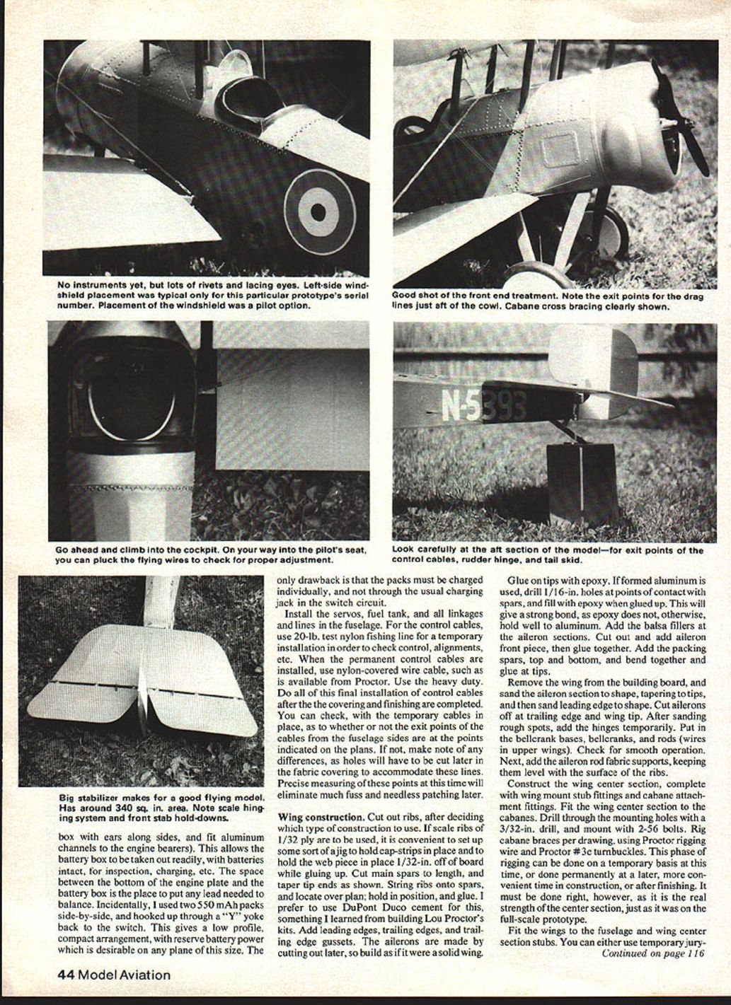
Fit aluminum channels or a box with ears along the engine bearers to allow the battery box to be removed readily with batteries intact for inspection or charging. The space between the bottom of the engine plate and the battery box is the place to add any lead needed for balancing. The author used two 550 mAh packs side-by-side and hooked them up through a "Y" yoke back to the switch for a low-profile, compact arrangement with reserve power. Note: the packs must be charged individually and not through the usual charging jack in the switch circuit.
Install the servos, fuel tank, and all linkages and lines in the fuselage. For initial checks use 20-lb. test nylon fishing line for temporary control cables to verify control geometry and alignments. When installing permanent control cables, use nylon-covered wire cable (such as Proctor heavy-duty wire). Do the final installation of control cables after covering and finishing are completed.
Check, with temporary cables in place, whether the exit points for the cables from the fuselage sides match points indicated on the plans. If not, make note of differences so holes can be cut later in the fabric covering to accommodate these lines. Precise measuring now will eliminate much fuss and needless patching later.
Wing construction
Cut out ribs after deciding which type of construction to use. If scale ribs of 1/32-in. plywood are used, set up a jig to hold cap strips and the web piece 1/32-in. off the board while gluing. Cut main spars to length and taper the tips as shown on the plans. String ribs onto spars and locate them over the plan; hold in position and glue. DuPont Duco cement is recommended for this work. Add leading edges, trailing edges, and trailing-edge gussets. The ailerons are made by cutting out later, so build as if the wing were solid.
Glue on tips with epoxy. If formed aluminum is used for tips, drill 1/16-in. holes at points of contact with spars and fill with epoxy when glued up—this gives a stronger bond because epoxy otherwise does not hold well to aluminum. Add balsa fillers in the aileron sections and cut out and add the aileron front piece, then glue together. Add packing spars top and bottom, bend together and glue at the tips.
Remove the wing from the building board and sand the aileron section to shape, tapering to the tips, then sand the leading edge to shape. Cut ailerons off at the trailing edge and wing tip. After sanding rough spots, add the hinges temporarily. Install bellcrank bases, bellcranks and rods (wires in upper wings) and check for smooth operation. Next, add aileron rod fabric supports, keeping them level with the rib surfaces.
Construct the wing center section complete with mounting stub fittings and cabane attachment fittings. Fit the wing center section to the cabanes. Drill through the mounting holes with a 3/32-in. drill and mount with 2-56 bolts. Rig cabane braces per drawing, using Proctor wire and Proctor #3 turnbuckles. This phase of finishing can be done temporarily now and finalized later; it must be done right, as it is the real strength of the center section, just as on the full-scale prototype.
Fit the wings to the fuselage and wing center-section stubs. You can either use temporary jury-rigged interplane struts now or cut and shape finished interplanes as closely as possible. At each stub fitting, drill through carefully centered on the sub-spar with a 5/64-in. drill. Remove wings and drill out spar stub ends to 7/64-in. to clear 4-40 bolts. Tap 4-40 threads into the copper wing center section and fuselage stubs. Reinstall the wings and insert 4-40 x 3/4-in. bolts through each point. Fit so that wing stubs slide in and out and the bolts pass through and tighten without difficulty.
Control system
Rudder
- Use a pushrod from the servo to the rudder pedal; ball-socket links are recommended.
- Locate the link on the rudder pedal as close as possible to the connection point of the control cable to avoid differential rudder.
- Run cables from the rudder pedal under the seat and Nyrod-covered bearing bar, then back to the rudder horns.
Elevator
- Run elevator wires from the servo arm, one from each side of the arm, under the bearing bar. The lower cables run out the side of the fuselage at the exit points noted on the plan to the lower end of the elevator horn.
- The upper cables, after leaving the bearing bar, run over small pulleys (Proctor) on top of the fuselage to the top of the elevator horns. Include a small turnbuckle in each upper cable for adjustment, as per full-scale practice.
- Use adjustable clevises on each side of the servo output arm for trimming. A Du-Bro #111 threaded coupler and clevis clip will work well.
Ailerons
- The aileron controls use a bellcrank assembly amidships. Run a pushrod from each side of a long servo arm to each side of the long arms on the center bellcrank.
- Make short rods connected to the short ends of the bellcrank, using ball-socket connections, out through the fuselage side about 1/2-in., with an eye formed on the outside of the fuselage.
- These eyes connect to eye-end rods running to the lower wing aileron bellcranks with 2-56 bolts and locknuts.
- On the top wing a cable connects the two top aileron bellcranks with a hook disconnect under the center of the wing center section. The upper and lower ailerons are connected by a cable; a small turnbuckle at the bottom end allows adjustment to balance the ailerons.
- Remember the aileron circuit runs in a continuous circle: a right turn command pulls the left aileron down; this action, through the upper/lower connections and bellcranks, raises the right aileron.
This rigging is reliable and allows disconnect and removal of wings in pairs without upsetting fixed rigging parameters.
Rigging
Rigging may be carried out either before or after painting the wings. It is probably best done before painting, then dismantled, painted and final-rigged later. Rigging is critical—take your time and follow the directions below.
- Assemble strut and rigging fittings at all points on the wings. Use Proctor fittings or make up your own. All flying wires are double; landing wires are single. Use Proctor #3 turnbuckles at all indicated points (these are scale size as confirmed by factory drawings). Proctor heavy-duty rigging wire is recommended.
- Set the fuselage in a level position. If you have an incidence gauge (highly recommended), the wing center section should give 2½° positive incidence and the stabilizer 0°. Correct now if needed—this is the foundation for rigging.
- Install the wing stub fittings into the fuselage and cabanes and bolt in place. Block up the lower wings so they have 3° of dihedral and 2½° of positive incidence. Fit interplane struts carefully so the upper wings show the same dihedral and incidence as the lower wings.
- Drill holes through the struts at the fittings and bolt on using Proctor #210 bolts or equivalent. Do not move the plane or any of the blocks during this time or you will need to recheck everything.
- Install the interplane strut bracing wires and the landing and flying wires semi-tight. Check dihedral and incidence and adjust gradually with the turnbuckles until all wires are tight and all specs are correct. Properly done, the wings are now permanently rigged; with all turnbuckles safety-wired in place, they can be removed and transported without further checks. Plan to spend two or three evenings on this phase.
- Install the drag wires. The author used light springs on each side of the firewall to give slight tension. The wires exit through the side cowl and connect to the upper and lower rear interplane strut fittings. A convenient connector can be made from small swivel snaps used on fishing lines. These are the only rigging parts removed at disassembly. Tension is not critical—keep them reasonably taut.
Field assembly then consists only of sliding the interplane struts into position, securing the 4-40 x 3/4-in. bolts, connecting the upper aileron wires and affixing the drag lines.
Finishing touches
Covering can now be done. Super Coverite is recommended as it gives a good fabric look, is tough, and can be painted with very few coats. Bring the covering on the fuselage right up to the lips of the front decking and cowling edges.
Study photographs of the full-scale aircraft you are copying to get correct access hatches, rivet detail, and other small but important items. If making the 100-hp Monosoupape-powered version, be sure to put the cowl bulge on the right side—those models were the only ones so equipped; all other cowls were smooth.
Rivets can be made from 5/64-in.-head escutcheon nails. Lacing eyes are about 1/16-in. diameter, so use pins with this size head and stagger the lacing per the plan detail.
For the cockpit surround, the author made up beading from thin leather with a piece of clothesline rope laminated in the fold; this was cemented and stitched around the cockpit opening. A dummy engine can be made from Williams Bros. 3-in.-scale LeRhône cylinders.
Wheels in the proper size (6½-in. dia.) can be obtained from Lou Perretti or from Williams Bros.
Flying
After sorting out the plane, it performed very well. As with any WW I model, flying in strong winds is difficult, but the plane handles moderate winds with no difficulty.
Initial flights can be made without the cowl to enable proper engine adjustments. Be sure to add the equivalent weight of the cowl (lead or similar) to the nose during such tests. With the cowl added back, the plane is cleaner and will fly better due to less frontal drag.
On takeoff, it is easiest to add up-elevator trim to prevent the tail from lifting too high before takeoff speed is attained, which can otherwise cause a nose-over. Let the plane run out and gain flying speed, then gradually relax the up elevator. Some slight rudder correction may be needed; keep the nose directly into the wind. Under low-wind conditions, the plane will not take off by itself without added up elevator. After lift-off, let it climb out and remove the up-elevator trim. Get some altitude before turning. Turns can be made with ailerons alone, coordinated rudder and ailerons, or just rudder. Each feels different—learn which you prefer for various maneuvers.
All actions happen slowly—scale flight is what you get. There is nothing prettier than a low, slow fly-by with this big biplane.
Landings should cause no problem. Set up far enough out, throttle back to idle and begin descent. If it sinks too fast, add gentle throttle. Let it settle onto the field at its own pace and begin the final flare at about 3–4 ft. off the deck with full up-elevator at set-down. If it looks like it will nose over, punch the throttle and hold full up-elevator. Let it roll out, then taxi to the hangar. Ground handling is reasonable for a skid-equipped taildragger on dirt or grass.
Anyone willing to tackle this plane will be duly rewarded by the challenge of building and the showmanship of flying a large vintage biplane. There should follow many hours of exciting and enjoyable flying. If competition-oriented, this plane, done right, should be very competitive in AMA Precision Scale, Sport Scale, or Giant Scale.
Acknowledgments
The author extends thanks to a number of individuals without whom this plane and article would not have been possible:
- Brian Voyer, draftsman, who did the basic drawings in his Seekonk High School drafting class under Bruce Downing and assisted at the field.
- Leo Opdycke, for generous advice, information and constructive criticism.
- Lou Perretti, for periodic advice and for steering the author into WW I Quarter Scale.
- Friends and flying companions of the South Shore Radio Control Club for encouragement and assistance.
- The author's wife for her patience during the many hours spent on this project.
References
- Profile Publications—#139 Bristol Scouts C & D.
- Bristol Aircraft Since 1910 — C. H. Barnes.
- British Aeroplanes 1914–1918 — J. M. Bruce.
- Model Airplane News — June 1978.
- Airpower — November 1975.
- World War I Aeroplanes. #58 — August 1976. #65 — November 1977.
15 Crescent Rd., Poughkeepsie, NY 12601.
Transcribed from original scans by AI. Minor OCR errors may remain.

