
Buck 600
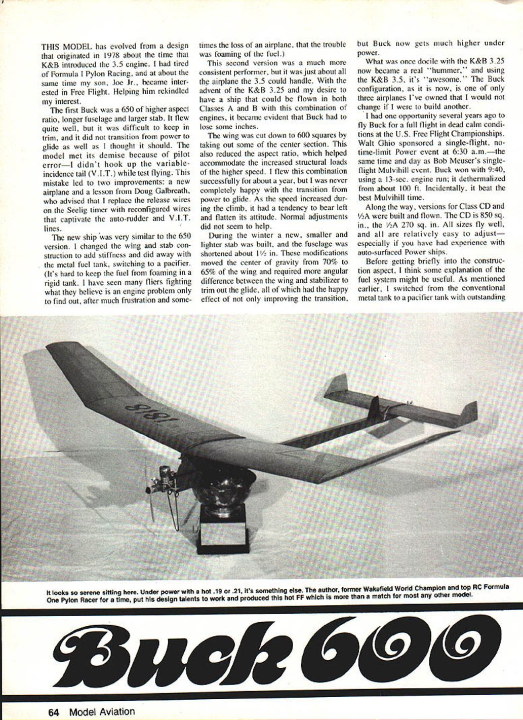
This model evolved from a design that originated in 1978, about the time K&B introduced the .35 engine. I had tired of Formula I pylon racing, and around the same time my son Joe Jr. became interested in Free Flight. Helping him rekindled my interest.
The first Buck was a 650: higher aspect ratio, longer fuselage and larger stabilizer. It flew quite well but was difficult to keep trimmed and did not transition from power to glide as well as I thought it should. The 650 met its demise because of pilot error—I didn't hook up the Variable-Incidence Tail (V.I.T.) while test flying. This mistake led to two improvements: a new airplane and a lesson from Doug Galbreath, who advised replacing the release wires on the Seelig timer with reconfigured wires that captivate the auto-rudder and V.I.T. lines.
The next ship was similar to the 650 but with stiffer wing and stab construction and a switch from a metal tank to a pacifier tank. Rigid metal tanks are prone to fuel foaming; many fliers fight perceived engine problems when the real trouble is foaming in the tank. The pacifier solved that problem.
The second version was a much more consistent performer but was about all the .35 could handle. With the advent of the K&B .325 and my desire to fly the ship in both Classes A and B with these engines, the Buck lost some wing area. The wing was cut to 600 sq. in. by removing part of the center section, which also reduced aspect ratio to better handle increased structural loads at higher speed.
After flying the 600 configuration for about a year I was never completely happy with the power-to-glide transition. During the climb it tended to bear left and flatten. Over the winter I built a smaller, lighter stabilizer and shortened the fuselage about 1½ inches. These changes moved the center of gravity from about 70% to 65% of the wing chord and required more angular difference between wing and stabilizer to trim the glide. The modifications improved the transition and significantly increased altitude under power. What was once docile with the K&B .325 became a real "hummer"; with the K&B .35 it is "awesome." The current Buck configuration is one of only three airplanes I've owned that I would not change if I were to build another.
I once flew Buck in a full flight during dead-calm conditions at the U.S. Free Flight Championships. Walt Ghio sponsored a single-flight, no-time-limit Power event at 6:30 a.m. (the same time and day as Bob Meuser's single-flight Mulvihill event). Buck won with 9:40 using a 13-second engine run; it dethermalized from about 100 ft and beat the best Mulvihill time that day.
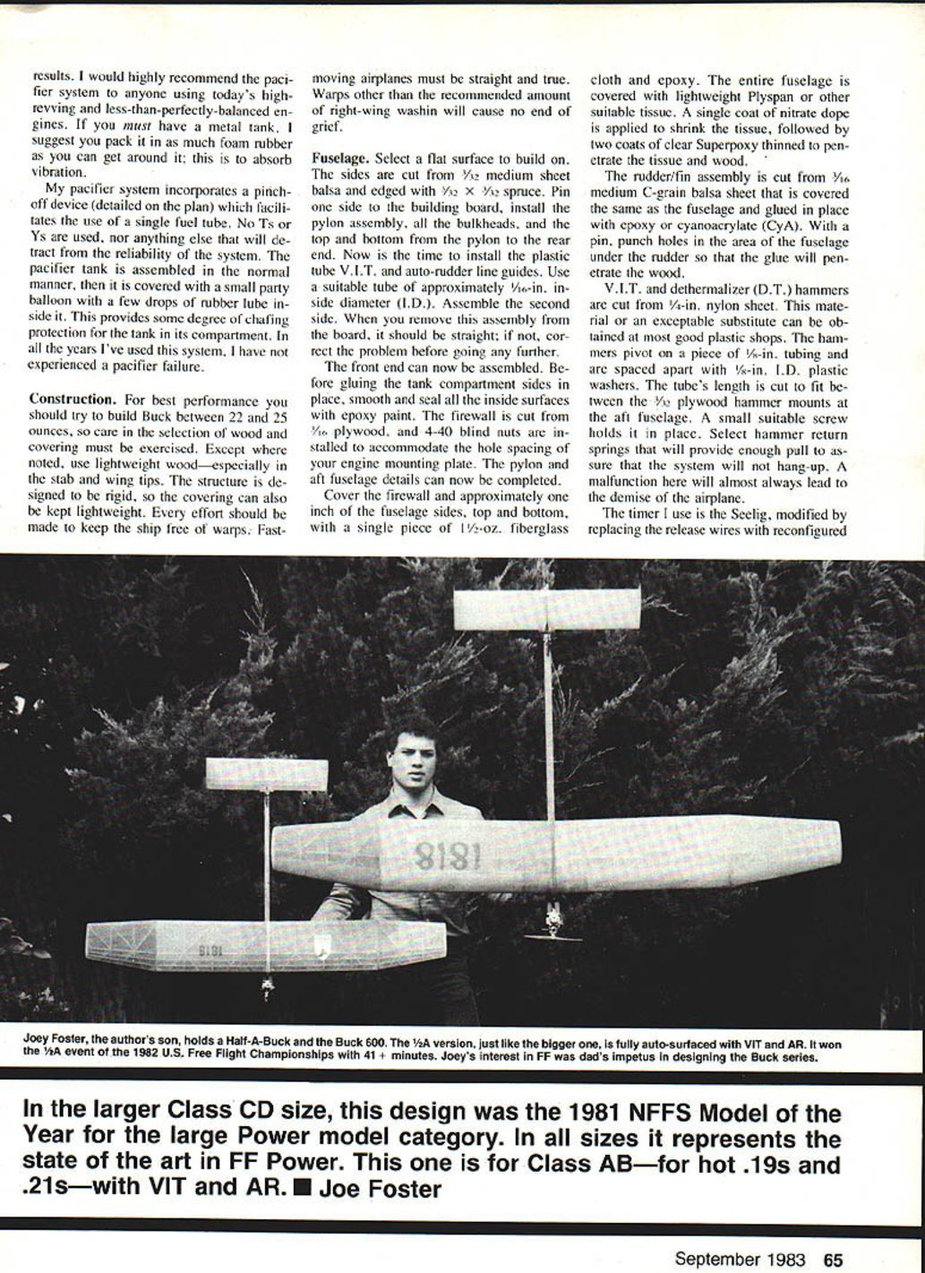
Versions for Class C/D and 1/2A were also built and flown. The CD version is 850 sq. in.; the 1/2A is 270 sq. in. All sizes fly well and are relatively easy to adjust, especially if you have experience with auto-surfaced power ships.
Fuel system
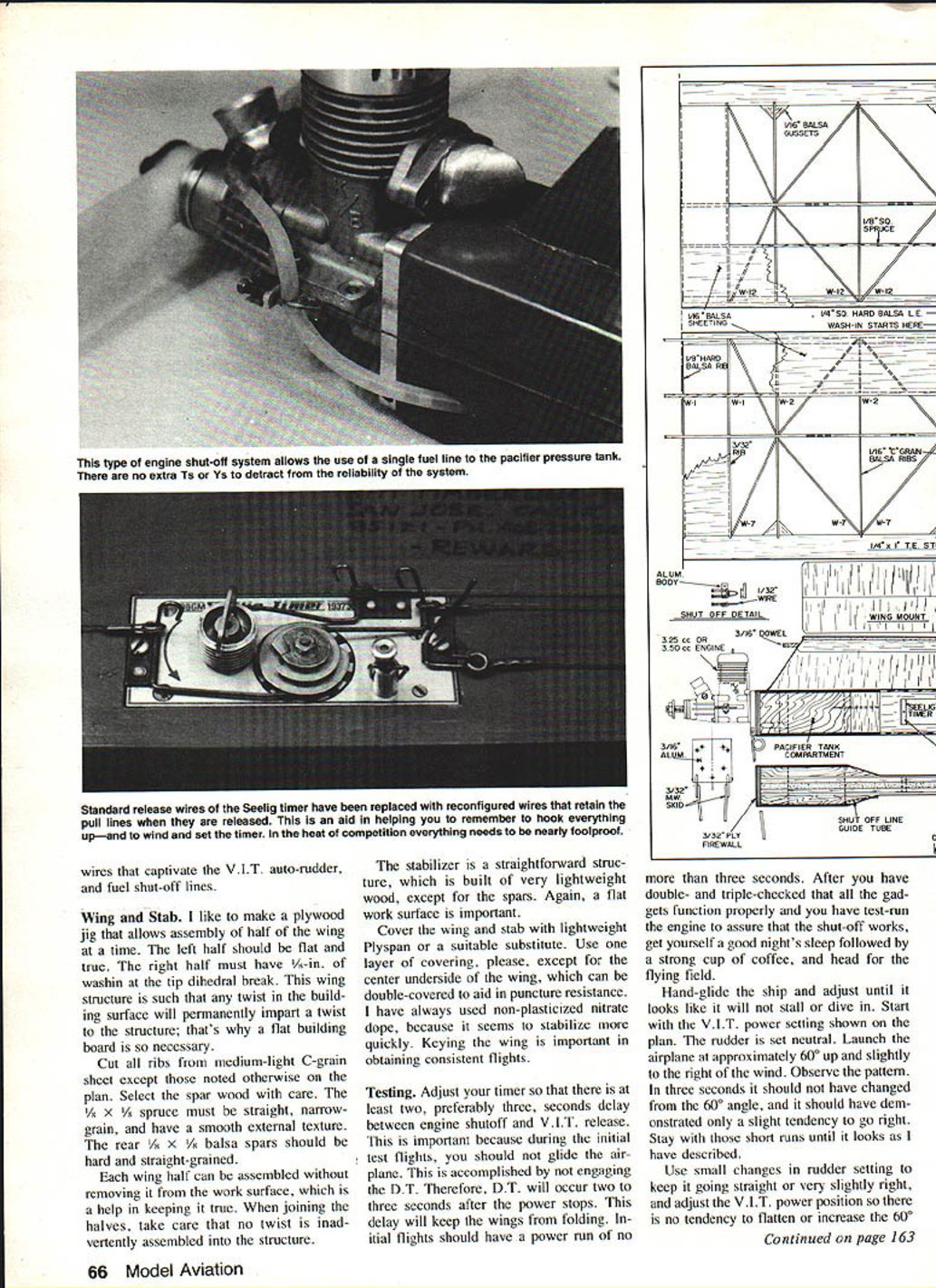
I strongly recommend the pacifier tank over a conventional metal tank. The pacifier system incorporates a pinch-off device (detailed on the plan) and allows a single fuel tube—no T's or Y's that can reduce reliability. Assembly notes:
- Assemble the pacifier tank in the normal manner.
- Cover it with a small party balloon; a few drops of rubber lubricant on the side provide chafing protection inside the tank compartment.
- The pacifier system has proven reliable; in years of use I experienced no pacifier failures.
If you must use a metal tank, pack as much foam rubber around it as possible to absorb vibration and prevent foaming.
Construction
For best performance try to build the Buck between 22 and 25 ounces. Careful selection of wood and covering is essential. Except where noted, use lightweight wood—especially for the stabilizer and wing tips. The structure is designed to be rigid; covering can be kept lightweight. Keep the ship free of warps—fast-moving airplanes must be straight and true. Warps, or too much right-wing washin, will cause no end of grief.
General tips:
- Use lightweight Plyspan or a suitable tissue for covering.
- Key the wing carefully to obtain consistent flights.
- Use non-plasticized nitrate dope for quicker stabilization, followed by penetrating coats of thinned epoxy (Superpoxy) or equivalent varnish.
Fuselage
- Select a flat building surface.
- Cut two medium-sheet balsa sides and edge them with 1/32 x 1/8 spruce.
- Pin sides to the building board and install the pylon assembly, bulkheads, top and bottom pylon pieces and rear end.
- Install plastic-tube V.I.T./auto-rudder line guides (use tubing ~1/16 in. I.D.).
- Assemble the second side and remove the assembly from the board; it should be straight.
Before gluing the tank compartment sides in place, smooth and seal all inside surfaces with epoxy paint. The firewall is cut from 1/8" plywood; install 4-40 blind nuts to match your engine mount plate hole spacing. Complete pylon and aft fuselage details.
Cover the firewall and approximately one inch of the fuselage sides, top and bottom with a single piece of 1-1/2 oz. fiberglass cloth and epoxy. Cover the entire fuselage with lightweight Plyspan or suitable tissue. Apply one coat of nitrate dope to shrink the tissue, followed by two coats of clear, thinned epoxy to penetrate the tissue and wood.
The rudder/fin assembly is cut from 1/16" medium C-grain balsa, covered like the fuselage, and glued in place with epoxy or cyanoacrylate. Punch small holes in the fuselage under the rudder so glue will penetrate the wood and form a strong bond.
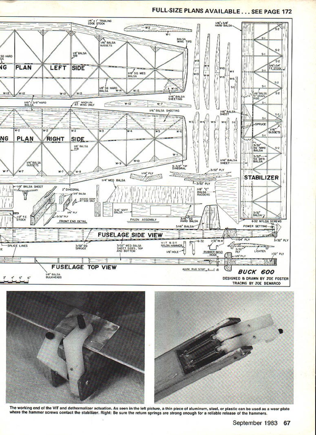
V.I.T. and dethermalizer (D.T.) hammers are cut from 1/4" nylon sheet (or similar plastic). Details:
- Pivot the hammers on a piece of 1/16" tubing and space them with 1/16" I.D. plastic washers.
- Cut the tube length to fit between the 1/8" plywood hammer mounts at the aft fuselage and secure with a small screw.
- Select return springs that provide enough pull to prevent hang-ups—malfunction here will almost always cause loss of the airplane.
Modify the Seelig timer by replacing the release wires with reconfigured wires that captivate the V.I.T., auto-rudder and fuel shutoff lines.
Wing and Stab
I recommend making a plywood jig to assemble half the wing at a time. Build the left half flat and true; the right half should have 1/8" wash-in at the tip dihedral break. A flat building board is critical—any twist in the surface will permanently impart twist to the wing.
- Cut ribs from medium-light C-grain sheet (except where the plan notes otherwise).
- Select spar wood with care: the 1/8 x 1/4 spruce spars must be straight, narrow-grained and smooth; the rear 1/8 x 1/8 balsa spars should be hard and straight-grained.
- Assemble each wing half on the work surface and take care that no twist is introduced when joining the halves.
- The stabilizer is straightforward: build it from very lightweight wood except for the spars, again on a flat surface.
Cover the wing and stab with lightweight Plyspan (or equivalent), using one layer except under the center underside of the wing, which may be double-covered for puncture resistance. Use non-plasticized nitrate dope and be meticulous about keying the wing.
Testing
- Adjust the timer so there is at least a two, preferably three, second delay between engine shutoff and V.I.T. release. This delay prevents the wings from folding during initial tests.
- Initial flights: do not engage the dethermalizer (D.T.). Use short power runs of no more than three seconds during initial testing.
- Hand-glide the ship first and adjust until it neither stalls nor dives. Start with the V.I.T. power setting shown on the plan and set the rudder neutral.
- Launch at approximately 60° up and slightly to the right of the wind. In three seconds the airplane should still be at approximately 60° and show only a slight tendency to go right.
- Use small rudder changes to keep it straight or very slightly right. Adjust the V.I.T. power position to eliminate any tendency to flatten or reduce the 60° angle.
- Increase engine run in one-second increments, observing pattern and correcting adverse tendencies. A good power pattern is 70°–80° up and approximately a half-turn to the right in 10 seconds.
- If you must use more than about 1/16" of right rudder to obtain the correct right tendency during power, you probably have too much washin in the right wing panel. Correct the washin and start over rather than fighting it.
- Once you have safe power runs over five seconds, you may begin gliding. Glide adjustments are done by changing the D.T. hammer setting to alter stabilizer incidence. All test flights up to that point should be flown under full power.
Final notes
I have enjoyed many pleasurable years flying the Buck design. In its various sizes it has rewarded Joe Jr. and me with national records in Classes A, B, C and D, and it has won consistently at the U.S. Free Flight Championships and other important contests. I hope you have as much success and pleasure with yours.
Transcribed from original scans by AI. Minor OCR errors may remain.

