
Build the Tigercat A Big Electric
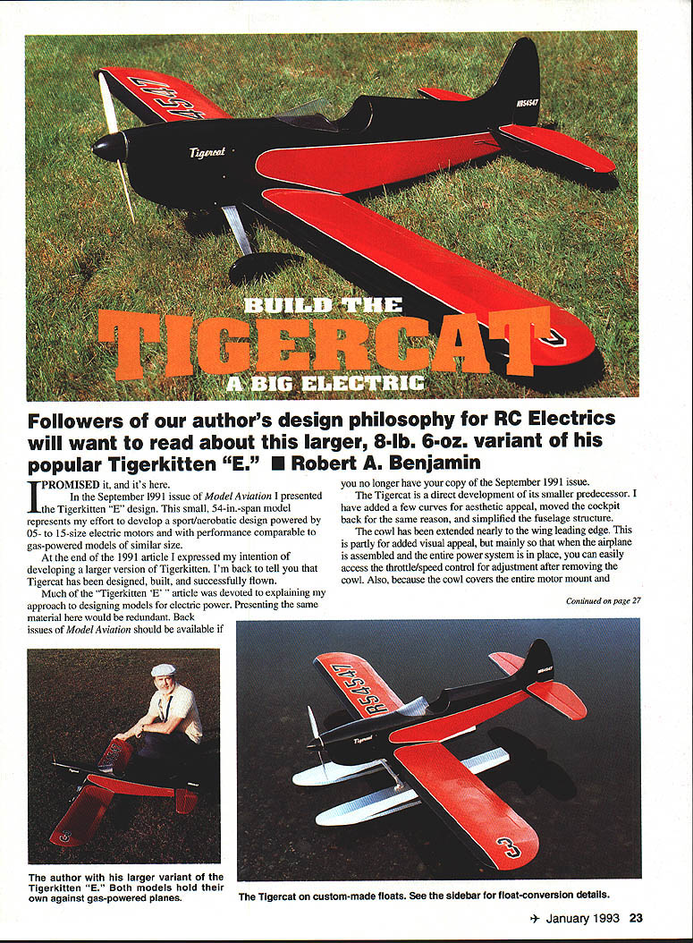
Followers of our author's design philosophy for RC electrics will want to read about this larger, 8-lb. 6-oz. variant of his popular Tigerkitten "E."
Robert A. Benjamin
I promised it, and it's here.
In the September 1991 issue of Model Aviation I presented the Tigerkitten "E" design. This small, 54-in.-span model represents my effort to develop a sport/aerobatic design powered by .05- to .15-size electric motors with performance comparable to gas-powered models of similar size.
At the end of the 1991 article I expressed my intention of developing a larger version of Tigerkitten. I'm back to tell you that Tigercat has been designed, built, and successfully flown.
Much of the "Tigerkitten 'E'" article was devoted to explaining my approach to designing models for electric power. Presenting the same material here would be redundant. Back issues of Model Aviation should be available if you no longer have your copy of the September 1991 issue.
The Tigercat is a direct development of its smaller predecessor. I have added a few curves for aesthetic appeal, moved the cockpit back for the same reason, and simplified the fuselage structure.
The cowl has been extended nearly to the wing leading edge. This is partly for added visual appeal, but mainly so that when the airplane is assembled and the entire power system is in place, you can easily access the throttle/speed control for adjustment after removing the cowl. Also, because the cowl covers the entire motor mount and firewall area, you can experiment with changes in the motor and gearbox installation without messing up the finish. This elongated, tightly fitted cowl was demanding to build up, but you don't have to do the work: Fiberglass Master, Inc. has made both the cowl and wheel pants available for purchase.
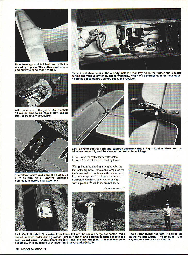
My airplane flies on a geared Astro Cobalt 40 using a 21-cell, 1,200-mAh battery pack and an Astro Model 207 speed controller. This combination turns a cleaned-up Zinger 13 x 8 prop at about 7,400 rpm with a static current drain of 27 amps at full throttle. Flight control is via my old reliable Airtronics Championship 7, using standard-size servos and an SR airborne battery pack.
Thus equipped, Tigercat easily accomplishes quick takeoffs even from thick, wet grass. Level cruising flight can be maintained at about 60% power. Roll performance is crisp. The plane executes good sequential loops; level flight does best inside a square loop.
I designed the airplane slightly larger than necessary so that you can experiment with extra power. The airplane will easily carry the extra weight of higher-capacity cells, making it practical to use the Astro Cobalt FAI 40.
The prototype model weighs about 8 lb. 6 oz. I chose a traditional dope-and-fabric finish (Sig nitrate dope and Supercoat butyrate over Koverall) for classic appearance and long-term durability. Fans of plastic film coverings can probably save 4 to 6 ounces.
Although I haven't tried it, an Astro 40 standard 18-cell battery pack should give good performance in models at the lower end of the weight range.
Likewise, an Astro 60 sport-wind or pattern-wind motor on 28 1,200-mAh cells would give the model serious aerobatic potential at a still-comfortable wing loading. I'd very much like to hear from anyone who tries an Astro 60 in this design.
Construction
Since the Tigercat is absolutely not for first-time builders, I won't go into a lot of detail. I will, however, share a few suggestions.
Unless you're very sure of what you're doing, don't modify the structure. There's just enough there to do the job and still withstand the occasional rough-and-tumble that Mother Nature hands our airplanes; I don't believe in trying to build crashproof models. Resist the temptation to reinforce the structure; after a year of intensive flying, I've found no weak areas. Use good, light balsa—leave the really heavy stuff for the hackers. And don't spare the sanding block!
Wing
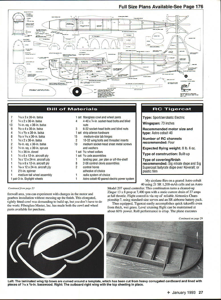
Begin by making a template for the laminated tip bows. (Make the templates for the laminated tail surfaces at the same time.) I cut my templates from heavy corrugated cardboard and lined each working edge with a piece of 1/16 x 3/8-in. basswood. A solid, nonstick base for the lamination process will be assured if you glue the wood edging securely and wax it by rubbing with a spare candle.
Working with one wood strip at a time, wet the piece lightly and draw it around the template. If you've chosen your wood carefully, this should be easy. Use plastic sheet or waxed paper under the form to prevent sticking. Secure the strips temporarily by inserting heavy pins along the outer edge of the template. With the inner strip pinned in place, apply a generous bead of Hot Stuff UFO Thick to the inside of each strip, moving the pins to the outer edge as you work your way around the template. Keep each strip in tension while working it into place.
If the first strip doesn't come out to your satisfaction, consider it a practice exercise and do another. It's really not that difficult, and the results are worth the effort.
Give the finished laminate a shot of Kick-It accelerator, allow it to set for a few moments, and remove it from the template. The slight springback won't be a problem when the part is assembled to the structure. Allow all laminated parts to dry overnight, then true them up with a sanding block.
Make a template for cutting out the wing ribs. A W-6 template can be used to make a full count of generic ribs, which can then be trimmed as necessary to make the variant ribs.
Cut the trailing edge (TE) from 1/4-in. sheet, beveling it as shown in the W-3 wing section drawing and slotting it to accept the back ends of the ribs. Position the lower 1/4-in.-sq. spar on the board, trial-fit several W-5s, and position the trailing edge, shimming in 1/32 in. off the board. Add the top 1/4-in.-sq. spar, still without gluing, and adjust the TE shim as necessary until the 1/4-in.-sq. spars lie one above the other perpendicular to the board.
Now you can assemble all the ribs for real, followed by the top spar and the trailing edge. I used Hot Stuff UFO Thick for all gluing operations, with an occasional shot of the thin formula for in-place assembly.
To finish framing the wing panel, add the leading edge, fit the top web, and add the 3/32-in. tip base parts. The latter parts lend stiffness to prevent distortion under covering loads.
True the top surface of the wing with a careful sanding. Install the leading edge and center section sheeting, including the quarter-round radius pieces at the center, the trailing edge cap, and the rib cap strips.
Make the ply spar doublers. Turn the panel over, and block it square on the board. Install the doublers, and true up the bottom surface.
Install the aileron control horn assembly against the inside of the top sheet, then add the bottom sheeting to close up the panel.
Build the aileron, using the completed wing panel as a guide to ensure a proper fit. Use the W-3 wing cross-section drawing as a guide in beveling the aileron leading edge.
If you have a hinge-building board, you can assemble the left panel around the protruding spar doubler ends; otherwise, follow the same assembly sequence you used for the first panel. Make sure the left panel fits in place on the spar doublers before you close the bottom surface.
You may want to join the panels before adding the bottom sheet. In any case, make certain the panels are in proper alignment. The desired 6° total dihedral angle depends on the spar doublers being correctly aligned.
Build the second aileron. Add the 3/32-in. ply reinforcement under the center section trailing edge. Open up the top center section for the aileron servo. Sand the control horn block and hinge area smooth everywhere until you are satisfied.
Tail surfaces
Don't expect to just whack some shapes out of 3/8-in. sheet. These tail surfaces require a little extra effort, but the results are well worth it.
Begin the horizontal tail by laying out the 3/8-in. sq. members and the 1/4-in. dowel elevator joiner, leaving a minimal hinge gap between the stabilizer leading edge and the elevator leading edge. Assemble the laminated parts around these parts so that the structure is initially built as one piece.
Add the 1/8-in. ply TE doubler and the 1/8 x 3/8-in. ribs, followed by the center section structure and the elevator TE gussets. Note that a 3/8-in.-wide opening is left at the center so that R-1 can be extended to fit flush with the bottom surface of the horizontal tail after assembly.
Cut the laminated parts at the tips. Remove the assembly from the board, and sand it well. Shape the outer edges to a 3/16-in. radius; there is no taper on the airfoil section.
Build the vertical tail and rudder the same way. Leave the forward portion of the vertical tail leading edge unsanded until after assembly to the fuselage, when the two portions can be blended together.
Fuselage
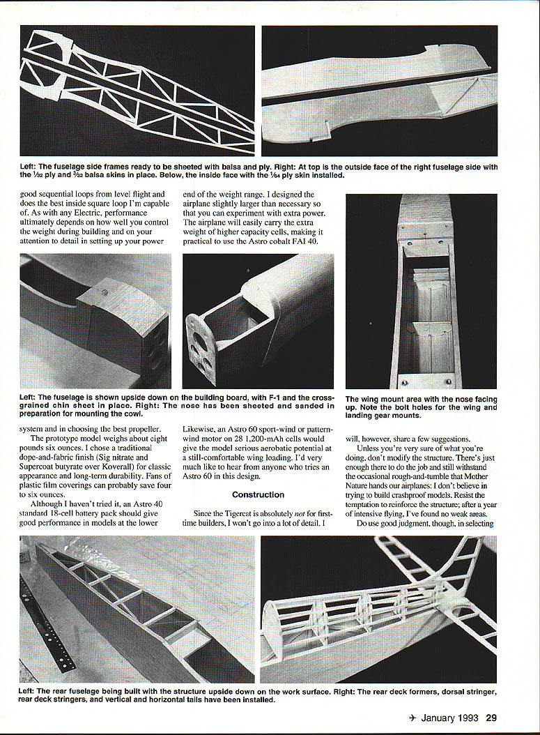
Pay close attention when laying out the fuselage side frames; there are lots of little pieces, and each one has to go in just the right place. Take it step by step, and you'll have a very sleek, functional fuselage in which everything fits just as intended.
The side frames are based on the 1/4-in.-sq. longerons and uprights/diagonal members. Note that the top longeron extends at the nose to fit into a notch in F-1 and ends flush with the front of that former. F-2, F-3, and F-6 are part of the basic side frame. Cut a slot forward of F-6 to accept F-5 later.
Build the first side, and block-sand the top surface to true it up. Cover the side with a clear protective sheet, then build the second side directly over it. (Be sure to build both a left side and a right.) Add the 1/32-in. ply nose sheeting and the 3/32-in. balsa sheeting to each side.
This sheeting forms the outer surface, or skin, of the fuselage. The nose sheeting, which lies inside the cowl, ends flush with the front vertical 1/4-in.-sq. member and will butt against the back of F-1. It extends to the top of the top longeron, to the bottom of F-2, and to the joint between the front of F-3 and the 1/4-in.-sq. diagonal, where the 3/32-in. balsa sheeting begins and where the back edge of the fiberglass cowl will fit. A 1/16-in. step is formed, which compensates for the thickness of the cowl wall. The 3/32-in. sheeting extends to the outside edges of the side frame.
Turn the side frames over, and add the 1/4-in. ply inside liner. Like the nose sheeting, the liner will butt against the back of F-1. The liner extends to the rear of the 1/4-in.-sq. vertical at the wing trailing edge, and the bottom lower edge is trimmed in a smooth radius down to meet the lower longeron. Cut a rectangular hole in the ply for F-7 and F-5. F-7 is inset into F-6; F-5 fits forward of F-6. Both formers rest against the inside of the 3/32-in. sheeting.
Cut out the remaining formers. Place the side frames upside down over the plan top to superimpose the sides, and join them at the top using 1/4-in.-sq. balsa crosspieces at the leading and trailing edge stations. Add F-5, F-4, F-7, and finally F-7A.
With the assembly still on the board, fit the wing saddle as necessary to square it in all axes. Use an incidence meter to make certain there is 3° positive incidence as indicated on the plan. Drill pilot holes through F-5 and into the leading edge for the 1/4-in. mounting dowels.
Remove the wing from the saddle, open up the holes, and install the dowels. Refit the wing, and put it back in place to make sure it still fits the saddle properly.
Drill through the trailing edge into F-7 for the 10-32 wing bolts. Install the bolts, and set the wing aside.
Reposition the main plate so that the fuselage can be placed upside down over the top elevation, with the nose off the edge of the board. That way, you can install F-1 and close up the nose with the fuselage squared over the plan.
Add F-1 and the cross-grained 3/32-in. balsa sheet skin covering. The latter has a 3/32-in. sheet inset, located forward of the landing gear, that forms a mounting lug for the cowl (see the plan).
Join the fuselage sides at the tail, and add the remaining 1/4-in.-sq. balsa crosspieces, the 3/32-in. cross-grained balsa belly sheet, and the 1/32-in. ply tail wheel mounting plate.
Remove the fuselage from the board. Install the horizontal tail, making sure it is mounted square.
Make the main landing gear as shown on the plan, or use an off-the-shelf unit; several will work with this airplane. The critical factors are adequate prop clearance and the widest possible tread. Also, be certain the gear can be adjusted for camber and especially for toe-in (see the plans). As with almost any tail-dragger, ground handling becomes unpleasant without some toe-in on the main wheels.
Drill the landing gear and F-4 for three 6-32 screws. Countersink the holes in F-4 on the inside for blind nuts, and mount the gear.
Mount the tailwheel assembly to the ply baseplate. Remove the landing gear, and set it aside.
Assemble the rear-deck formers F-8 through F-12 and the cowl formers C-1 through C-5. Note that C-1 and C-2 are recessed, and that C-2 rests directly against C-3. Add the top stringers between C-1 and C-3 and the top 1/4-in.-sq. stringer between F-8 and F-12. Adjust the tops of the tail formers, if necessary, so that the top 1/4-in. stringer lies straight and meets the leading edge of the vertical tail when it is trial fitted. When you are satisfied with the fit, mount the vertical tail permanently, fitting the bottom portion of R-1 into the slot in the horizontal tail.
Add the side stringers to the rear deck, followed by the sheet-balsa fairing at the horizontal tail root. The fairing forms a base for the fuselage when in place, but is attached to the rails with a minimum of six sheet‑metal screws and washers for easy removal. Note also that the rear portion of the tray is a separate piece, designed to hold the rudder and elevator servos and the various switches and charging connections.
Trial-mount your equipment, fit the control surface horns and hinges, and hang the control surfaces without gluing to satisfy yourself that everything works as intended. As you no doubt realize by now, one of the subtle advantages of electric power is that you can test-run your power system at this point without making an oily mess of the structure.
Fit the fiberglass cowl after opening up an air intake hole at the front. An intake of the size shown in the photographs will provide good cooling. Because I demonstrate my airplane a lot, I have added a fan to accelerate postflight cooling of the motor and battery and allow charging soon after landing. Instead of waiting 20 minutes or so, I plug in the fan immediately after landing and have the pack at ambient temperature in 5 or 10 minutes. An inexpensive Radio Shack unit intended for cooling electronic installations, the fan is attached with Velcro as part of the installation and operated through a separate plug that connects directly to my 12-volt charging battery.
Depending on your construction technique and the thickness of your fiberglass cowl, you may have to either sand down the sheet structure forward of F-3 and between C-1 and C-2 or build up this area slightly with 1/64-in. ply to fit the cowl neatly. Some tolerance has been designed into this part of the structure to allow for individual differences.
Test-run the motor with the cowl and spinner in place. Fit the wheel pants, if you're using them. My wheel pants, which were molded from my own plug, proved to be a tight fit with Skylight wheels and had to be relieved somewhat at the lower edges. If you use a narrower wheel, this won't be a problem.
Make up brackets from aluminum or brass sheet, and secure them on the axle assemblies against the landing gear leg. Two short 2-56 bolts go through from the inside of the brackets and engage locknuts (the type with a plastic or fiber locking insert) that have been secured to the inside of the wheel pants with Hot Stuff. There is enough room inside for this to work, and if you rough up the inside surface of the fiberglass pants and fillet the nuts carefully with thixotropic-formula Hot Stuff, the installation is more than strong enough. Check the photographs to see what this looks like.
Final assembly and finishing
Pull everything apart, give the entire structure yet another sanding, and begin the covering and finishing process of your choice. I am a die-hard lover of dope and fabric, but the structure is rigid enough to work well with the plastic film coverings that many modelers prefer.
Regardless of the finishing system you choose, I strongly suggest that you reinforce the entire center section of the wing, as well as the fuselage back to the trailing edge, with light (0.75-oz.) fiberglass cloth applied over the bare balsa after sanding the wood as smooth as possible. I have used both polyester resin brushed directly through the cloth and thin-formula Hot Stuff. The latter is a bit more convenient.
- Spray a very light coat of 3M 77 adhesive over the area you're working on, and carefully lay the glass cloth in position.
- The 3M 77 will let you reposition the cloth, put it down exactly the way you want it, and then flow the Hot Stuff (UFO is the easiest to work with) directly into the cloth.
- When the cloth is just saturated, spray it lightly with Kick-It, followed immediately by a light block sanding and cleanup.
A single coat of primer, most of which is sanded off, provides a fine base for your covering. The whole process adds only two or three ounces to the airplane and strengthens the structure immensely. I wouldn't finish an airplane without it!
If you're using a painted finish, you may want to add the windshield after the covering has been applied and sealed. Cover the windshield with masking tape, leaving an exposed area about 8 in. wide at the base. Smooth the join line with judiciously applied filler and a careful sanding, and extend the paint job right up over the joint. When you pull off the tape, the windshield will look as if it's been molded right into the top cowl.
One aspect of the covering job requires special explanation. If you've seen my designs in print, you already know that I'm a devotee of fabric fairings at the base of the vertical tail. As a matter of fact, you can't build this airplane without making such a fairing. Relax—it's easy.
Cover the horizontal tail and then the fuselage bottom. Cut two pieces of covering large enough to cover one side of the fuselage from nose to tail, including the entire vertical tail. Leave yourself a generous margin of extra material to grab and work with.
Carefully cut a slot that will allow each of the two pieces in turn to fit around the root of the horizontal tail while also being positioned correctly to fit the rest of the fuselage. Attach the covering at the stab root, then from top to bottom along the leading edge of the vertical tail, and finally along a root or so of the lower longeron forward of the tail.
Doing some careful stretching and fitting, start attaching the covering at the center of the curve where the fin leading edge joins the top stringer, working your way toward the fin tip and forward along the stringer. Finish by attaching the material at all relevant points on the forward fuselage. The covering, whether plastic film or heat-shrink fabric, will cooperate by smoothly taking the edges with a minimum of wrinkling in the faired area. If you are careful to pull out as much slack as possible, shrinking the covering will produce a beautiful faired fabric fillet.
Do be careful not to shrink the fabric on the first side until you have covered the second side. If you're concerned that the highly stressed seam at the dorsal stringer might slip, punch a series of pinholes along the stringer and carefully seal the seam with thin-formula Hot Stuff before heat shrinking.
At this point you can permanently hinge the control surfaces and reinstall the radio and power components. The interior of the fuselage is tight, but there's room to install an Astro Cobalt 40 system neatly if you plan what you're doing.
Make sure the airplane balances as shown on the plan. Once you're comfortable with the model, you might want to experiment with moving the center-of-gravity back somewhat, but I suggest leaving it alone for test-flying.
I install my radio components (except the servos) with Velcro and use the same material on the motor battery. When the battery position and balance point have been established, cut several carefully located small holes in the plywood tray, and run two or three nylon cable ties through the holes. The 21-cell pack will stay in place during aerobatics, yet the cable-tie system won't interfere with cooling.
Flying
Be sure to range-check the radio both with and without the motor running. For your first few flights, try allowing the airplane a ground run of a hundred feet to be sure it gets aloft with plenty of airspeed. Once you're satisfied with the trim and low-speed handling, start experimenting.
One thing to be aware of: the Tigercat is so aerodynamically clean that it will go on for what seems like forever unless you slow it down well out in the landing pattern. Make a few practice approaches while you have plenty of go-around power in reserve.
Unless it is very windy, I find myself landing the airplane by pulling the power all the way off at least a hundred yards out in a normal approach glide. You'll probably find that your Tigercat prefers to be landed fast, on the main gear, rather than in a full-stall, three-point attitude. Once you're familiar with the model, I suspect you'll rapidly fall in love with it.
If you're trying to make up your mind whether to build this design, there's an Astro Flight video that will give you a chance to see what I'm talking about. The 30-minute tape includes several minutes' footage of early test flights with the Tigercat prototype. Contact Astro Flight directly for information about the video.
Think electric, and let me know how your Tigercat flies.
— Robert Benjamin
Transcribed from original scans by AI. Minor OCR errors may remain.

