
Building From Scratch
Part Two
by Bob Aberle
Covering and/or Painting
Last month I took you through the assembly of the Scratch-One up to covering and finishing. This month I’ll start Part Two with the covering and take you through the Scratch-One’s first flights. The full-size plans were published with Part One in the November issue.
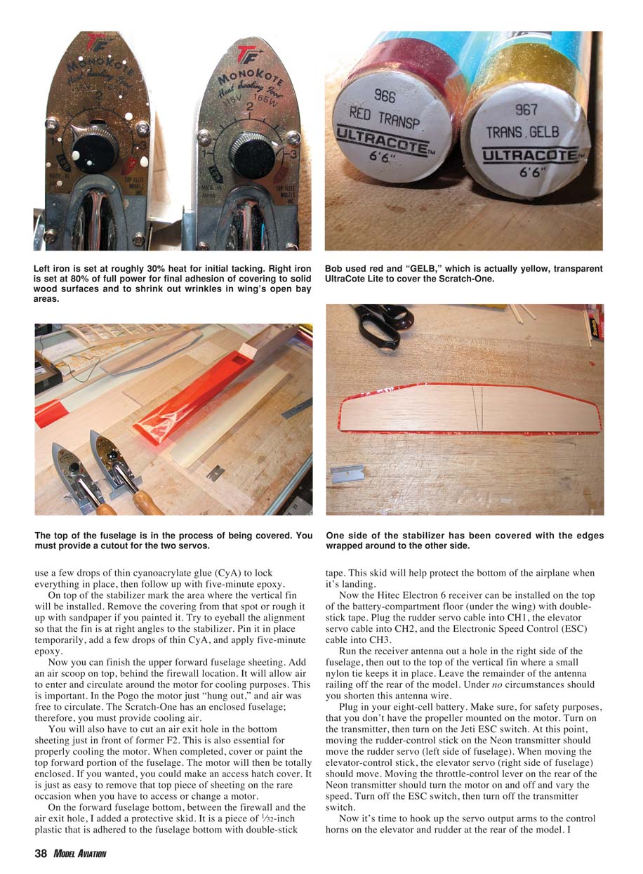
Whether you want to apply covering or paint is your choice. I opted to completely cover my Scratch-One with Carl Goldberg UltraCote Transparent Lite, an easy-to-use iron-on material. The wing must be covered since it is an open structure.
A good source for learning about applying UltraCote is Larry Sribnick of SR Batteries Inc. His technical newsletter series R/C Techniques includes Volume R-13 — Basic Covering Techniques — which details the entire process of applying UltraCote Lite to a model aircraft.
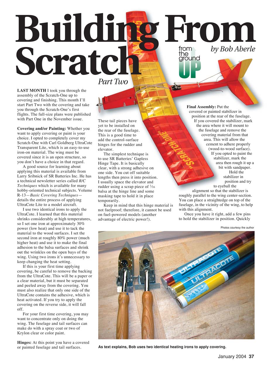
I use two identical irons to apply the UltraCote. I learned that this material shrinks considerably at high temperatures, so I set one iron at approximately 30% power (low heat) to tack the material to the wood surfaces, and the second iron at roughly 80% power (much higher heat) to make the final adhesion and shrink out wrinkles on the open bays of the wing. Using two irons avoids continually changing the heat setting.
If this is your first time applying covering:
- Be careful to remove the backing from the UltraCote (paper or clear material) — it must be separated and peeled away.
- Remember that only one side of the UltraCote contains the heat-activated adhesive. If you apply it on the reverse side, it will fall off.
For your first covering effort, you may want to concentrate only on the wing. The fuselage and tail surfaces can be finished with a spray coat or two of Krylon clear or color paint.
Hinges
With the fuselage and tail surfaces covered or painted but not yet installed, add the control-surface hinges for the rudder and elevator.
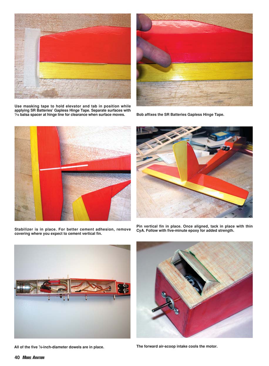
The simplest technique is SR Batteries’ Gapless Hinge Tape. It is clear with a strong adhesive on one side. Cut suitable lengths and press them into position. I usually space the elevator and rudder using a scrap piece of 1/16-inch balsa at the hinge line and some masking tape to hold it temporarily. Note: this hinge material is not fuelproof and cannot be used on fuel-powered models (an advantage of electric power!).
Final Assembly
- Stabilizer and fin
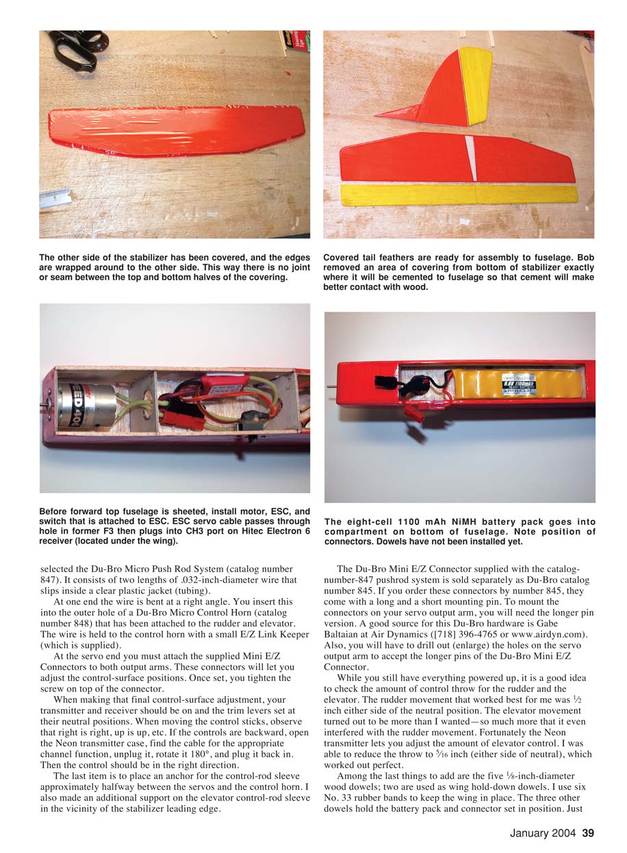
- Put the covered or painted stabilizer in position at the rear of the fuselage. If covered, mark the area where it will mount and remove the covering there so you have wood-to-wood contact for the cement. If painted, mark the area and rough it up with sandpaper.
- Eyeball the stabilizer so it is roughly parallel to the wing center-section. Use a straightedge on top of the fuselage near the wing to help alignment. Pin it in place, tack with a few drops of thin cyanoacrylate (CyA) to lock position, then follow with five-minute epoxy.
- On top of the stabilizer, mark the area for the vertical fin, remove covering or roughen the paint, and align the fin at right angles to the stabilizer. Pin, tack with CyA, and finish with five-minute epoxy.
- Forward fuselage sheeting and motor cooling
- Finish the upper forward fuselage sheeting and add an air scoop on top behind the firewall location to allow air to enter and circulate around the motor. This is essential because the Scratch-One has an enclosed fuselage.
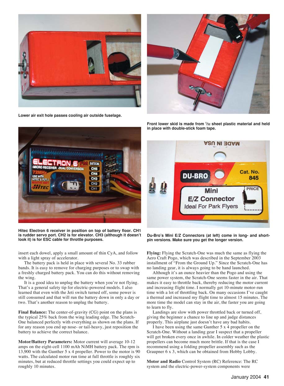
- Cut an air exit hole in the bottom sheeting just in front of former F2 to provide proper cooling airflow.
- Cover or paint the top forward portion of the fuselage when completed. You can make an access hatch if desired, but it’s often easiest to remove the top sheeting when servicing the motor.
- Protective skid
- On the forward fuselage bottom, between the firewall and the air exit hole, add a protective skid: a piece of 1/32-inch plastic adhered with double-stick tape to protect the fuselage during landings.
Radio, Receiver and Power Installation
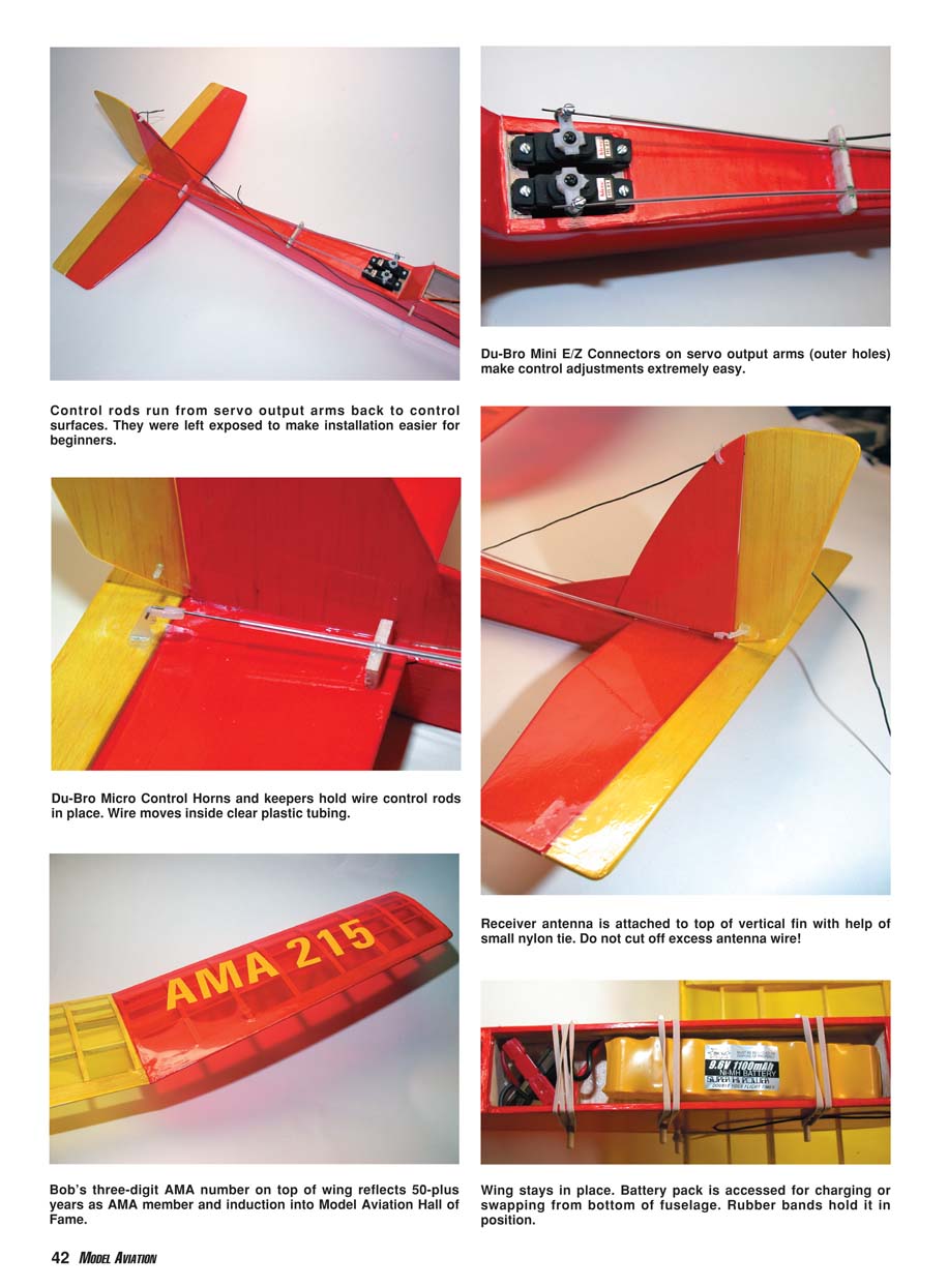
- Install the Hitec Electron 6 receiver on the top of the battery-compartment floor (under the wing) with double-stick tape.
- Plug the rudder servo cable into CH1, the elevator servo cable into CH2, and the Electronic Speed Control (ESC) cable into CH3.
- Run the receiver antenna out a hole in the right side of the fuselage, then up to the top of the vertical fin and secure it with a small nylon tie. Leave the remainder of the antenna trailing off the rear of the model. Do not shorten the antenna wire.
Pre-power check (safety):
- Make sure the propeller is NOT mounted on the motor.
- Turn on the transmitter.
- Turn on the Jeti ESC switch.
- Verify controls:
- Move the rudder stick: rudder servo (left side) should move.
- Move the elevator stick: elevator servo (right side) should move.
- Move the throttle: motor should turn on/off and vary speed.
- Turn off the ESC switch, then turn off the transmitter.
Control Linkages and Pushrods
I selected the Du-Bro Micro Push Rod System (catalog number 847). It consists of two lengths of .032-inch-diameter wire that slip inside a clear plastic jacket (tubing).
- At the control-surface end the wire is bent at a right angle and inserted into the outer hole of a Du-Bro Micro Control Horn (catalog number 848), which is attached to the rudder and elevator. The wire is held to the control horn with the supplied E/Z Link Keeper.
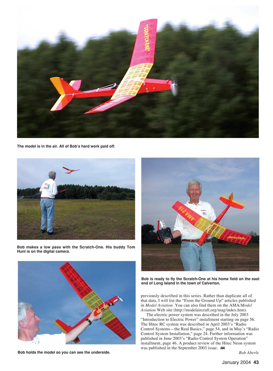
- At the servo end attach the supplied Mini E/Z Connectors to both output arms. These let you adjust control-surface positions; tighten the screw on top of the connector once set.
- Mounting the connectors: the Du-Bro Mini E/Z Connector supplied with the pushrod system is available separately as Du-Bro catalog number 845. If ordered by number 845, they come with a long and a short mounting pin. You will need the longer pin version to mount on your servo output arm. Drill out the holes on the servo output arm to accept the longer pins.
- A good source for Du-Bro hardware is Gabe Baltaian at Air Dynamics: (718) 396-4765 or www.airdyn.com.
Anchors and supports:
- Place an anchor for the control-rod sleeve approximately halfway between the servos and the control horn.
- Add an additional support on the elevator control-rod sleeve near the stabilizer leading edge.
Connecting to control surfaces:
- I cut a slot in the trailing edge of the rudder and elevator and epoxy in a 1/8-inch wire loop. Use a pushrod with a keeper to connect to the loop.
- Cut down and bend the control horns so they are not proud of the control surface.
When making the final control-surface adjustment:
- Have the transmitter and receiver on with trim levers at neutral.
- Move the control sticks and confirm directions: right is right, up is up, etc.
- If controls are reversed, open the Neon transmitter case, unplug the appropriate channel cable, rotate it 180°, and plug it back in.
Control Throws
While powered up, check control throws:
- Rudder: 1/2 inch each side of neutral worked best for me.
- Elevator: I started with large throw but reduced it using the Neon transmitter to 5/16 inch each side of neutral because the larger throw interfered with rudder movement.
Dowels, Wing Hold-Down and Battery Retention
- Install five 1/8-inch-diameter wood dowels: two are used as wing hold-down dowels and three hold the battery pack and connector set in position.
- Use six No. 33 rubber bands to keep the wing in place.
- Insert each dowel, apply a small amount of thin CyA, and follow with a light spray of accelerator.
- The battery pack is held in place with several No. 33 rubber bands for easy removal for charging or swapping without removing the wing.
Safety tip: unplug the battery when you're not flying. Even with the Jeti switch turned off, some power may still be consumed and can drain the battery in a day or two.
Final Balance
The center-of-gravity (CG) point on the plans is the typical 25% back from the wing leading edge. My Scratch-One balanced properly at 2-1/4 inches behind the leading edge at the wing center. If you end up nose- or tail-heavy, reposition the battery to achieve the correct balance.
Motor/Battery Parameters
- Motor current: averages 10–12 amps on the eight-cell 1100 mAh NiMH battery pack.
- RPM: 13,900 with the Gunther 5 x 4 propeller.
- Power to motor: about 90 watts.
- Calculated motor run time at full throttle: roughly 6 minutes; at reduced throttle expect up to roughly 10 minutes. In practice, with throttling back I normally get 10 minutes and have occasionally stretched flights to almost 15 minutes by using thermals.
I used a small folding propeller and a Jeti 35 ESC which gave good throttle control. In colder weather plastic props get more brittle; for protection consider a folding propeller such as the Graupner 6 x 3 (available from Hobby Lobby).
Flying
- The Scratch-One is hand-launched (no landing gear).
- It has a brisk climb and flies smoothly. Trim the elevator slightly for level flight and verify the rudder for coordinated turns.
- Its light wing loading makes it very responsive and aerobatic. Landings are slow with power throttled back or off, giving beginners time to line up and judge distances.
- The protective skid helps protect the fuselage bottom during landings.
- The airplane has no bad habits; start with power and radio components similar to those I used and adjust as needed. Fly safely and have fun.
Motor and Radio Control System (RC) Reference
The RC system and electric-power-system components were previously described in this series and in the "From the Ground Up" articles in Model Aviation. Rather than duplicate that data, here are relevant references (available on the AMA/Model Aviation website: http://modelaircraft.org/mag/index.htm):
- July 2003 — "Introduction to Electric Power" (starting on page 56)
- April 2003 — "Radio Control Systems — the Real Basics" (page 54)
- May 2003 — "Radio Control System Installation" (page 24)
- June 2003 — "Radio Control System Operation" (page 46)
- September 2003 — product review of the Hitec Neon system
Notes and photos from my Scratch-One:
- Control rods run from servo output arms back to control surfaces and are left exposed to make installation easier for beginners.
- Du-Bro Micro Control Horns and keepers hold wire control rods in place; the wire moves inside clear plastic tubing.
- Receiver antenna is routed to the top of the vertical fin and secured with a small nylon tie; do not cut off excess antenna wire.
- Wing stays in place with rubber bands; battery pack is accessed from the bottom of the fuselage.
MA Bob Aberle
Transcribed from original scans by AI. Minor OCR errors may remain.

