
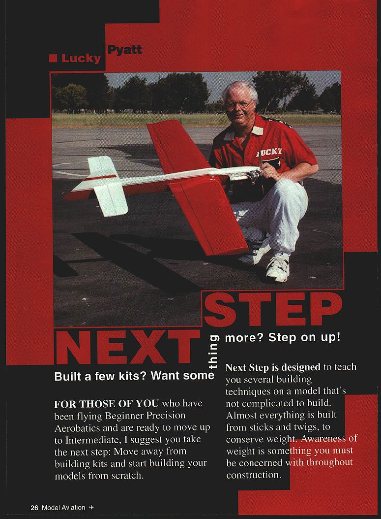
Built a few kits? Want something more? Step on up!
Lucky Pyatt
FOR THOSE OF YOU who have been flying Beginner Precision Aerobatics and are ready to move up to Intermediate, I suggest you take the next step: move away from building kits and start building your models from scratch.
Next Step is designed to teach several building techniques on a model that's not complicated to build. Almost everything is built from sticks and twigs to conserve weight. Awareness of weight is something you must be concerned with throughout construction.
CONSTRUCTION
Wing
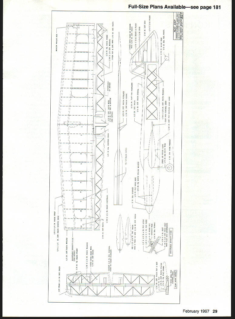
I suggest you start with the wing, since it is the most time-consuming to build. To make a straight wing you need a straight, flat building surface. Lay out the wing plan and tape it down.
- Build 10 support jigs from 1/8" balsa:
- Cut a sheet 2" wide lengthwise.
- Cut off 2½" widths and cut 20 pieces with a Zona saw or miter box.
- Make braces by cutting 1½" squares and slicing them on a diagonal to yield 20 triangles.
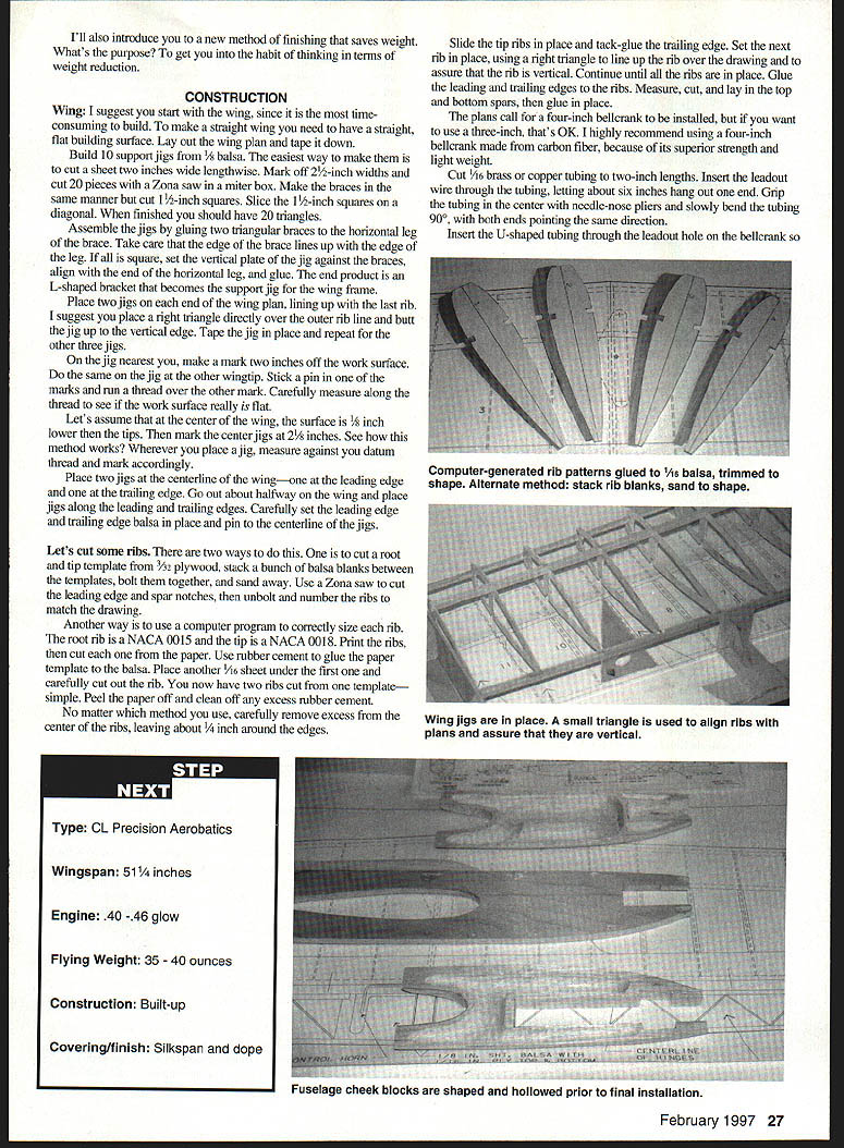
- Assemble each jig by gluing two triangular braces to the horizontal leg; align edges carefully. Set the vertical plate against the braces, align with the end of the horizontal leg, and glue. The result is an L-shaped bracket that becomes the support jig for the wing frame.
- Place two jigs at each end of the wing plan, lining up with the last rib. Place a right triangle directly over the outer rib line and butt the jig up to the vertical edge; tape each jig in place.
- Check work surface flatness:
- On the jig nearest you mark 2" off the work surface; do the same at the other wingtip.
- Stick a pin in one mark and run a thread over the other mark. Measure along the thread to see if the surface is flat.
- If the center is lower (for example 1/8" lower), mark the center jigs at 2½". Wherever you place a jig, measure it against the datum thread and mark accordingly.
- Place two jigs at the centerline of the wing—one at the leading edge and one at the trailing edge. Place additional jigs about halfway along the wing and along the leading and trailing edges. Carefully set the leading-edge and trailing-edge balsa in place and pin to the centerline jigs.
Ribs:
- Two methods:
- Make root and tip templates from 3/32" plywood, stack balsa blanks between the templates, bolt them together, sand to shape, use a Zona saw to cut leading-edge and spar notches, unbolt and number the ribs.
- Use a computer program to size each rib (root = NACA 0015, tip = NACA 0018). Print and cut paper templates, glue to balsa with rubber cement, place a 1/16" sheet under the first and cut—yielding two ribs per template. Peel paper off and clean excess cement.
- Carefully remove excess from the center of the ribs, leaving about 1/4" around the edges.
Assembly:
- Slide tip ribs in place and tack-glue the trailing edge. Set each rib using a right triangle to ensure vertical alignment. Continue until all ribs are in place.
- Glue the leading and trailing edges to the ribs. Measure, cut, and install top and bottom spars and glue in place.
- The plans call for a 4" bellcrank, but a 3" is acceptable. I recommend a 4" carbon-fiber bellcrank for strength and light weight.
Bellcrank installation:
- Cut 1/16" brass or copper tubing into 2" lengths. Insert the leadout wire through the tubing, leaving about 6" protruding.
- Grip the tubing at the center and slowly bend it 90° so both ends point the same direction. Insert the U-shaped tubing through the leadout hole in the bellcrank so the short legs come back about 1/4" from the end of the upper horizontal leg.
- Bend the upper tip down about 30° and the lower tip up about 30°.
- Bring the leadout wires together and wrap with soft copper wire about 1" long. Trim off the short piece of leadout wire and epoxy the wrapped wire instead of soldering — a light but very strong installation.
Wedges and sheeting:
- Cut two right-triangle pieces from 1/16" balsa. Make the short leg 1/2" and the long leg 1-1/2" (or follow plan dimensions). File a notch in the short leg just large enough for the bellcrank center post and place the notch away from the long leg.
- Glue the bottom wedge against the spar inboard of the root rib, leaving a little wood below the rib outline for finish-sanding. Install the bellcrank, pull leadouts through the ribs to the tip, center the bellcrank on the root rib centerline, and place the second wedge. Leave a little material to sand to contour.
- Rib strength is completed when you apply the top and bottom center sheeting; in-flight pull forces will be distributed along spars and sheeting.
Trailing edge and web sheeting:
- Cut and install bottom trailing edge sheeting.
- Install vertical-grain 1/16" balsa web sheeting in four rib bays left and right of the root ribs.
- Cut and glue top trailing edge sheeting in place.
Flap control build:
- Temporarily install the flap control horn.
- Cut 1/8" music wire about 7" long and put an 80° bend 1" in from one end. File a flat spot on the leg that goes through the bellcrank; install the pushrod and secure with a wheel collar. Ensure the setscrew tightens against the flat spot.
- Cut another 1/8" music wire about 5" long and put a 90° bend about 1" from one end. Put the short end in the control horn.
- Bring the two pushrod pieces together and wrap with soft copper wire, ensuring the bellcrank is square to the root rib and the control horn is vertical. Double-check, then solder the pieces together.
- Remove the finished pushrod, clean the solder joint, brush a coat of clear dope (to prevent rust), re-install, secure the wheel collar, and place a small dab of glue over the setscrew.
Leading edge sheeting:
- Glue the leading edge sheeting to the top and bottom spars. Lightly mist the sheeting so it curls down; let water stress-relieve one side, then gently pull the balsa to the leading edge and glue.
- After all pieces are glued, return the wing to the jig and check for warps. The wing must be free of twist.
- Cut and install the paneling that covers the last two ribs—bottom first, then top. Install center section sheeting and capspars.
- Remove the wing from the jig, finish the bottom center section and capspars. You now have a strong, warp-free wing.
Flaps
- The flaps are completely built-up. The area where the flap horn attaches is a box; the horn is not glued in final installation.
- Build the box from 1/8" balsa as per plans. Cover the top and bottom of the opening with 1/16" plywood about 1/8" wider than the opening. Finish trim with 1/16" balsa on the sides of the plywood.
- Insert the box in the flap framework and finish building as shown. Cover the entire flap with 1/32" balsa, cut and notch slots for the hinges, and sand leading and trailing edges to a clean half-round shape.
Adjustable leadout guides & wingtip weight box
- Adjustable leadout guides are simple and essential. The plans give all needed dimensions.
- To install a guide: draw the wingtip outline about 1/8" oversize, cut the tip in half lengthwise, tape halves together, and place the guide on the inside of the tip. Trace the guide outline, separate the halves, and carefully carve the guide seat about halfway through the tip.
- Tape the halves together again, place the guide, draw the 1/2" slot, separate halves, and cut the smaller slot for the leadout wires. Reassemble and check slot alignment. Adjust as needed.
- To prevent notch wear where leadout wires exit, cut two pieces of 1/4" plywood about 3/16" wide and long enough to fit in the leadout slot so wires rub against plywood instead of balsa.
- Fit the weight box in the outboard wingtip sheet. Trace rib outline on the tip sheet, cut the wingtip slightly oversize, glue the sheet in place, and finish-sand.
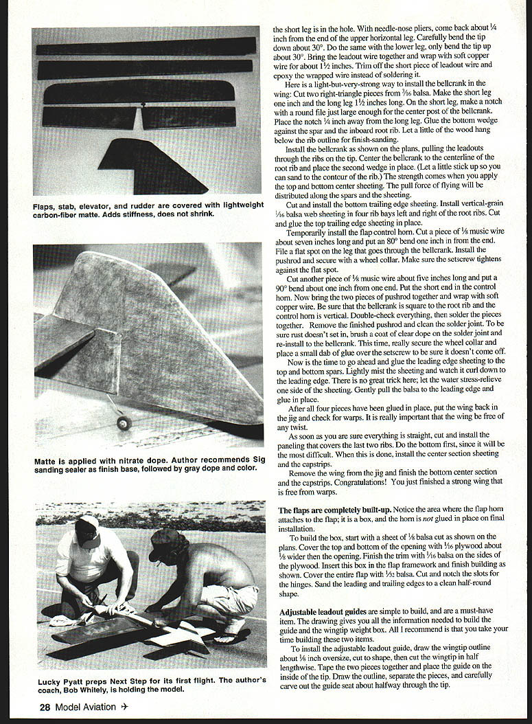
Tail surfaces
- Building stabilizer, elevators, and rudder is straightforward. Use the flap horn detail for the elevator horn box. Shape edges and cut hinge slots.
- After constructing flaps, stab, elevators, and rudder, brush on a coat of nitrate dope to help keep moisture out.
Fuselage
- Select a very light 3/8" balsa sheet. Strength and stiffness can mean extra weight—choose light stock.
- The fuselage is a box; use a long straightedge to scribe a top-edge reference line.
- Draw the engine centerline down the fuselage length and lay out engine mounts, wing, and stabilizer locations—check straightness carefully.
- Mark and trim excess area behind the wing using a razor plane. Re-measure and correct alignment now.
- Cut 1/16" plywood doublers per plans but don't glue yet.
- Lay the fuselage sheet over the plans and mark balsa webbing locations. Cut half-notches where webbing intersects using a 3/16" file with cutting teeth on the edge. Glue webbing and inboard ply doublers in place.
- Install and glue the engine mounts. Place outboard plywood doubler but don't glue yet. Remove plywood where engine and mounting lugs will be, then glue in place.
- Cut and install 3/16" aluminum pads slightly larger than mounting lugs on the maple engine mounts. Glue pads to the mounts, lay out mounting holes, drill, and install 4-40 blind nuts on the inboard side.
- Bolt engine in place and install prop and spinner. Use the spinner curve to draw the top and bottom fuselage contours, then remove the engine and cut off excess wood.
- Rough-cut 3/4" balsa cheeks to shape and tack-glue in place (use minimal glue so blocks can be removed for hollowing). Mark the fuel tank location on the outboard cheek and leave ~3/8" excess for adjustment. Remove cheeks, cut tank area, grind excess balsa, glue 1/16" balsa siding to the fuselage, trim the wing area, glue cheeks in place, and finish-sand.
- Shape and hollow fuselage cheeks prior to final installation.
FINISH
Covering options
- Wing covering option A: 000-weight silkspan.
- Sand wing with 400 wet-or-dry paper.
- Cut silkspan to size, dampen, place on outboard-bottom panel.
- Use nitrate dope thinned 50% around silkspan edges to adhere and smooth wrinkles.
- Turn wing and apply silkspan to outboard-top panel, overlap ~1/2" along centerline.
- Use a mister to prevent drying too quickly. Allow to dry; wet trailing edge and correct warps with moisture as needed.
- Repeat for inboard panels.
- After drying and warp correction, apply a coat of thinned nitrate dope to the wing, let dry a couple hours, sand lightly to remove fuzz, then apply one more coat to open bays.
- Wing covering option B: 1/5-ounce carbon-fiber matte (recommended instead of silkspan for other parts).
- This matte has no grain and will not shrink; cut each piece to exact size.
- Use thinned nitrate to apply the matte. Since it does not shrink, you can let one side dry before applying the other.
- Use the matte on flaps, stab, elevators, rudder, and fuselage (up to where cheeks end). Do cheeks after wing and cheeks are installed.
- Sand parts with 320 wet-or-dry paper (dry use). Do not sand through edges; check smoothness by hand.
Sanding sealer and final prep
- Apply sanding sealer (Sig brand recommended) to all surfaces including the wing. This is a butyrate dope—watch for warping as it dries.
- Let first coat set overnight. Sand with 320 paper to remove powder; be gentle.
- Apply a second coat of sealer and let dry overnight. Use small sanding blocks to regain flatness.
- Hold sanded surfaces to a light source to find shiny spots (areas not yet sanded). If you see very flat, non-reflective spots you may have sanded through—repair and re-seal as needed. Keep sanding until every piece has a velvet shine and smooth texture.
FILLETS
- Prepare the area with 1/2" masking tape placed about 3/16" away from the joint.
- Use Sig Epoxy-White (or similar epoxy) and mix per directions. Place epoxy in the fillet joints, pressing down to remove air bubbles.
- Shape fillets using chrome-plated sockets: 1/4" socket for small fillets, 1/2" socket for larger ones. Put the socket on a 6" extension for final shaping. Hold the socket at about 45° off the fuselage and 45° forward; apply pressure and pull toward the nose to form a smooth fillet.
- As epoxy warms and begins to harden, wet your finger and gently smooth the fillet—do not press hard. This knocks down any tape edge and blends the final shape.
- Let cure 24 hours, then sand lightly with 320 paper to roughen the surface for paint.
ASSEMBLY
- Install landing gear and bolt to the fuselage.
- Set the fuselage upside down and brace it so sides are vertical; you will be moving the wing in and out several times.
- Insert the wing into the fuselage, brace, and check for level across both wing and fuselage. Adjust until perfectly aligned—have a helper if possible. Once satisfied, glue wing in place.
- Before installing the stabilizer, level the model so the wing is level in both axes (Robart leveling tool recommended).
- Place a long level on top of the fuselage; the bubble should read level. Insert stabilizer and put a level on its spanwise surface. Measure distance from trailing edge of stab tip to trailing edge of wing; adjust until sides are equal, tilt stabilizer until level, then tack-glue. Double-check and glue in place.
- For the rudder, ensure the fuselage is vertical and use a right triangle to check placement before gluing.
- Glue fuselage cheeks in place and finish with matte and sealer. Cut and glue the 1/2" sheet for the canopy and long turtledeck, and form the rudder dorsal fin. Apply finish to the cheeks.
Fillets check
- When fillets are fully cured and sanded, remove the masking tape.
ASSEMBLY FINISHING STEPS
- Inspect every part; wipe down with a damp cloth to remove dust.
- Apply Sig Gray (or similar) as first color coat—just enough to cover. Inspect surfaces, fix flaws, and sand color off as needed.
- Optional: spray another light gray coat for uniformity.
- Use 1/8" x 1/4" plastic automotive trim tape for hard paint edges. If using butyrate dope, spray a light coat of clear along edges and let dry ~30 minutes before applying tape to prevent bleed. When removing tape, pull back over itself for a clean cut. If using epoxies, wait at least 24 hours before removing paper and tape.
- Assemble flaps and elevator, install pushrod, engine, tank, and accessories to make the model flyable.
TRIMMING
- Start trim before the first flight:
- Balance (CG): Pick up the model by the canopy. If the CG is very close to the front of the wing the model is nose heavy—add weight until it balances just over the spar location on the wing. This is critical.
- Extend the CG perpendicular to the fuselage out to the inboard wingtip. Adjust leadouts so they are 1/2" behind that line.
FIRST FLIGHT
What to look for:
- Wings level: Have someone watch for level wings. If an outboard wing is consistently up or down, twist the outboard tip in that direction. If the outboard wing is low both right-side up and upside down, remove 1/4 oz of tip weight. Continue until wings are level both ways.
- Engine sound inverted: Engine sound should be steady inverted and upright. If the engine goes flat when inverted, raise the tank 1/8". Try different props and fuel blends for best performance; consult an expert if needed.
- Pull on the handle (line tension): If pull is light and the model is unresponsive, check engine pointing and add a little engine offset to increase line tension. Verify leadout location—leadouts should be behind the CG. If the model pulls to the right, check engine offset and leadout location and adjust accordingly.
- Balanced control input: Inside and outside loop pull should be balanced; up and down control must be equal. If inside maneuvers require significantly more input than outside, adjust the elevator work-link. Fine-tune turning with handle adjustments. Work with an experienced flier if unsure.
The goal is a model trimmed for predictable, stable Precision Aerobatics so you can practice rather than fight the model. Properly trimmed, Next Step should carry you through Intermediate and on to Advanced (and possibly Expert).
Lucky Pyatt 9629 Hazard Garden Grove, CA 92644
SPECS
- Type: CL Precision Aerobatics
- Wingspan: 51"
- Engine: .40–.46 glow
- Flying weight: 35–40 oz
- Construction: Built-up
- Covering/finish: Silkspan or carbon-fiber matte, dope
SOURCES
- Balsa:
- Superior Aircraft Balsa
- 1202 Centralia St., Unit G, Hawaiian Gardens, CA 90716
- Phone: (310) 865-3220
- Fax: (310) 860-0327
- E-mail: balsa@ix.netcom.com
- Control system hardware:
- Control Specialties Corp.
- 205 E. Center St., Box 68, Stockertown, PA 18083
- Engines, props, and other goodies:
- T & L Specialties
- Box 6052, Torrance, CA 90504
- List of other fliers near you:
- PAMPA
- 158 Flying Cloud Isle, Foster City, CA 94404
Transcribed from original scans by AI. Minor OCR errors may remain.

