
BUMBLED-BEE
An Easy-B canard that consistently has turned in flights of 8 to 9 minutes under 50- to 65-foot ceilings.
- Jean G. Pailet
IT WAS ORIGINALLY intended to christen our little Easy-B canard the "Bass-ackwards," but in deference to the tender young eyes which may be reading this text we settled for "Bumbled-Bee." In either case, the entire project has been a bumbled, bassackwards comedy of contradictions. But then you ought to expect the collaboration of an RC columnist and a CL Contest Board member to result in an unusual indoor model!
The author (past CLCB chairman and present CLCB member) developed the design from a concept initiated by George Myers (writer of the monthly Radio Technique column in Model Aviation). The original fun-fly model evolved into a competitive airplane and we are now experimenting with a larger version of the Bumbled-Bee in the Indoor Paper Stick event (page 15 of the December 1976 issue of MAN has photos of Barry Pailet with the canard he flew in the Paper Stick event at the 1976 Nationals).
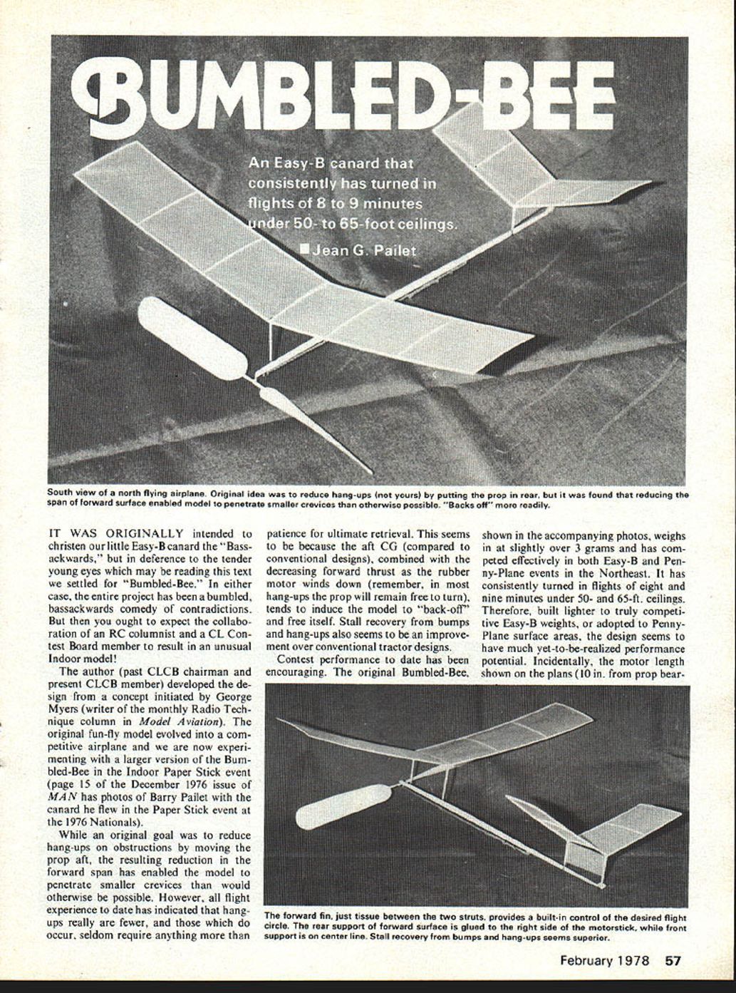
While an original goal was to reduce hang-ups on obstructions by moving the prop aft, the resulting reduction in the forward span has enabled the model to penetrate smaller crevices than would otherwise be possible. However, all flight experience to date has indicated that hang-ups really are fewer, and those which do occur, seldom require anything more than patience for ultimate retrieval. This seems to be because the aft CG (compared to conventional designs), combined with the decreasing forward thrust as the rubber motor winds down (remember, in most hang-ups the prop will remain free to turn), tends to induce the model to "back-off" and free itself. Stall recovery from bumps and hang-ups also seems to be an improvement over conventional tractor designs.
Contest performance to date has been encouraging. The original Bumbled-Bee, shown in the accompanying photos, weighs in at slightly over 3 grams and has competed effectively in both Easy-B and Penny-Plane events in the Northeast. It has consistently turned in flights of eight and nine minutes under 50- and 65-ft. ceilings. Therefore, built lighter to truly competitive Easy-B weights, or adapted to Penny-Plane surface areas, the design seems to have much yet-to-be-realized performance potential. Incidentally, the motor length shown on the plans (10 in. from prop bear- ing to rubber hook) conforms to Penny-Plane rules. If you plan to fly your Bumbled-Bee only as an Easy-B it would probably be advantageous to increase the motor length an inch or two. Doing so will give you added motor-winding capacity, as well as helping to keep the CG forward, where we want it.
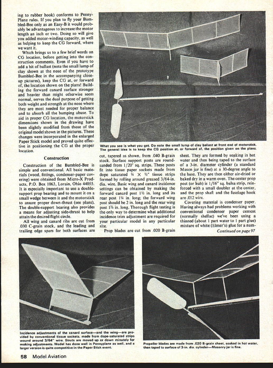
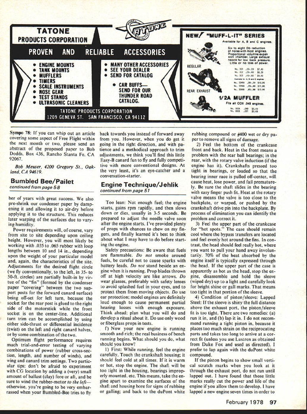
Which brings us to a few brief words on CG location, before getting into the construction comments. Even if you have to add a bit of ballast (note the small lump of clay shown at the nose of the prototype Bumbled-Bee in the accompanying close-up pictures), keep the CG at, or forward of, the location shown on the plans! Building the forward canard surface stronger and heavier than might otherwise seem normal, serves the dual purpose of getting both weight and strength at the nose where they are most needed for proper balance and to absorb all the bumping abuse. To aid in proper CG location, the motorstick dimensions shown in the drawing have been slightly modified from those of the original model shown in the pictures. These changes were incorporated in the enlarged Paper Stick model and proved quite effective in positioning the CG at the proper location.
Construction
Construction of the Bumbled-Bee is simple and conventional. All basic materials (wood, fittings, condenser-paper covering) were obtained from Micro-X Products, P.O. Box 1063, Lorain, Ohio 44055. It is especially important to use a double-support prop bearing and to mount it on a small wedge between it and the motorstick to assure proper down-thrust (see plans). The double-support bearing also provides a means for adjusting side-thrust to help attain the desired flight circle.
All wing and canard ribs are cut from .030 C-grain stock, and the leading and trailing edge spars for both surfaces are cut, tapered as shown, from .040 B-grain stock. Surface support posts are round-sanded from 1/20" sq. strips. These posts fit into tissue paper sockets made from dope-saturated 1/4 x 1/2" tissue strips formed by rolling around greased 3/64-in. dia. wire. Basic wing and canard incidence settings can be obtained by making the forward canard post 1 1/8 in. long and its rear post 1 1/4 in. long; the forward wing post should be 2 in. long and the rear wing post 1 7/8 in. long. Thorough flight testing is the only way to determine what additional incidence trim adjustments are required for your particular model in any particular site.
Prop blades are cut from .020 B-grain sheet. They are formed by soaking in hot water and then being taped to the surface of a 3-in. diameter cylinder (a standard Mason jar is fine) at a 30-degree angle to the base. They are then either air-dried or baked dry in a warm oven. The center prop post (or hub) is 1/16" sq. balsa strip, reinforced with a small doubler at the center, and the prop shaft and the fuselage hook are .012 wire.
Covering material is condenser paper. Having always had problems working with conventional condenser paper cement (normally shellac) we've been using a thinned (about 1 part water to 1 part glue) mixture of white (Elmer's) glue for a num- number of years with great success. We also pre-shrink our condenser paper by dampening it and allowing it to air-dry before applying it to the structure. This reduces later warping of the surfaces due to varying humidity.
Power requirements will, of course, vary from site to site depending upon ceiling height. However, you will most likely be working with .035 to .065 rubber with loop lengths between 10 and 14 in., depending upon the weight of your particular model and, again, the characteristics of the site. Adjustments for the desired right circle (we fly conventionally, to the left, in 35- to 50-ft. circles) are partially built in by virtue of the "fin" (formed by the condenser paper "covering" between the two support posts for the forward canard surface) being off-set for left turn, because the socket for the rear post is glued to the right side of the motorstick while the front socket is on the center-line. Additional turn trim can be accomplished by using either side-thrust or differential incidence (twist) on the left and right canard halves, or by some combination of the two.
Optimum flight performance requires much trial-and-error testing of varying combinations of power (rubber cross-section, length, and number of winds), and canard trim settings. Two particular tips: don't be afraid to experiment with CG location by adding a (very) small amount of ballast (clay) fore or aft, and be sure to wind the rubber-motor to the left—otherwise, you're going to be very embarrassed when your Bumbled-Bee tries to fly back towards you instead of forward away from you. However, when you do get it going in the right direction, and with patience and a methodical approach to trim adjustments, we think you'll find this little Easy-B canard fun to fly and fully competitive with more conventional designs. At the very least, it's an eye-catcher and a conversation-starter.
Transcribed from original scans by AI. Minor OCR errors may remain.

