
Bush Avenger
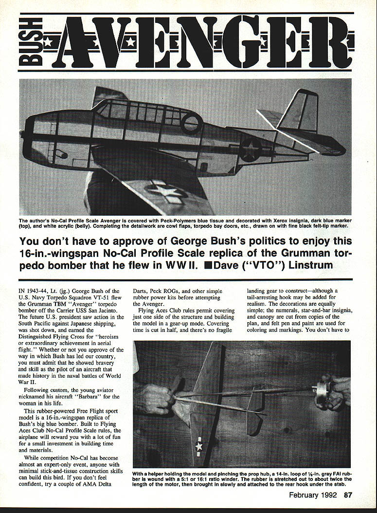
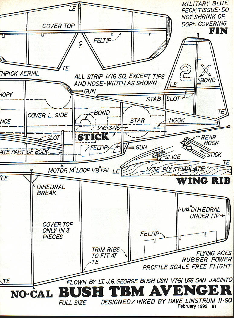
You don't have to approve George Bush's politics to enjoy this 16-in. wingspan No-Cal Profile Scale replica of the Grumman torpedo bomber he flew in WWII. In 1943–44 Lt. (jg.) George Bush of U.S. Navy Torpedo Squadron VT-51 flew the Grumman TBM "Avenger" off the carrier USS San Jacinto. The future U.S. president saw action in the South Pacific, was shot down, and earned the Distinguished Flying Cross for "heroism or extraordinary achievement in aerial flight." Following custom, the young aviator nicknamed his aircraft "Barbara."
This rubber-powered Free Flight sport model is a 16-in. wingspan replica of Bush's big blue bomber. Built to Flying Aces Club No-Cal Profile Scale rules, the airplane will reward you with a lot of fun for a small investment in building time and materials. While competition No‑Cal has become almost an expert-only event, anyone with basic stick-and-tissue construction skills can build this bird. If you don't feel confident, try a couple of simple rubber-power kits (Delta Darts, Peck ROGs) first.
Flying Aces Club rules permit covering only the top side of the structure and building the model gear-up. Covering time is cut in half and there's no fragile landing gear to construct—although a tail-arresting hook may be added for realism. Decorations are simple: numerals, star-and-bar insignia, and canopy are cut from copies of the plan; felt pen and paint are used for coloring and markings.
Materials
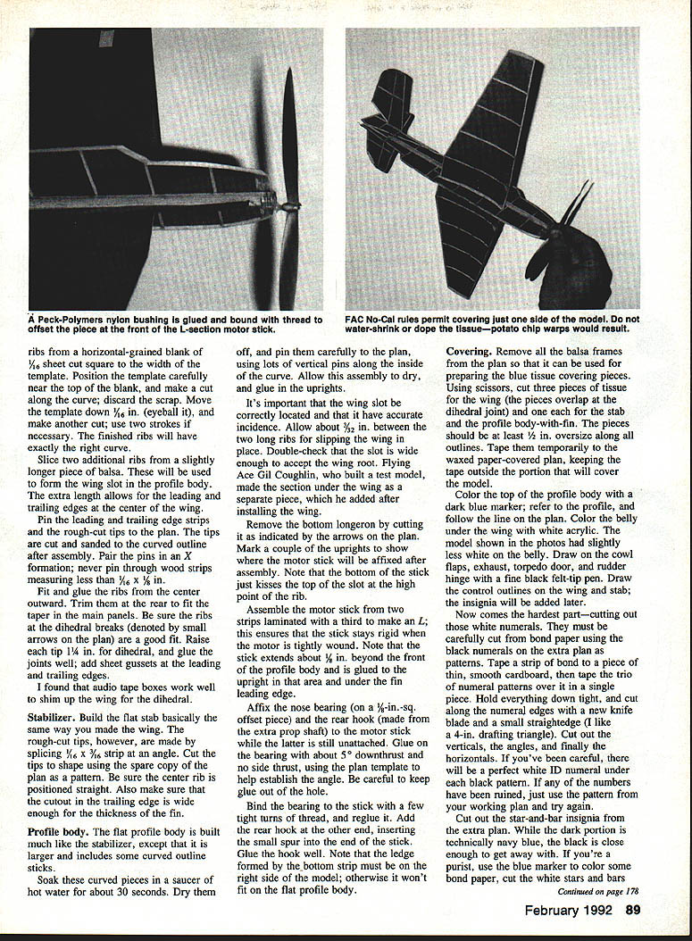
- One 1/16-in. sheet of medium straight-grained balsa and strips in three sizes: 1/16-in. square, 1/16 x 1/8 in., and 1/16 x 3/16 in. (or buy pre-cut strips). The 1/16-in. sheet will be used for slicing wing ribs.
- 1/32-in. ply for a rib template.
- Matched propulsion parts (Peck‑Polymers recommended): six-inch silver plastic prop, nylon nose bearing, prop shafts (plus an extra shaft that can be bent into a rear hook), and a length of Champion gray rubber. Be sure you have enough gumband to make several motors.
- One sheet Peck‑Polymers military blue Japanese tissue to cover the airframe.
- Elmer's Craft Bond white glue (thinned for tissue).
- Dark-blue waterproof marker and white acrylic craft paint for markings.
- Fine black felt-tip pen (Sharpie) for control outlines and detail.
- Hot Stuff UFO seven‑second cyanoacrylate (CyA) glue for motor hook and key joints. If seven‑second CyA makes joints too tight, use a slower-setting gap-filling CyA.
- Ordinary sewing thread for binding glued joints.
- Small supply of rubber lube or baby shampoo to prevent motor chafing.
- Small 5:1 ratio rubber winder (Peck‑Polymers).
- Building surface: ceiling tile or artist's Fome‑Core large enough for the full plan; smooth, flat, and soft enough for dressmaker's straight pins (T‑pins).
- X‑Acto knife with #11 blade, small scissors, needle‑nose pliers.
- Two 11 x 17‑inch Xerox copies of the full‑size plan. Tape one to the building board and use the other for cutting rib templates, tip patterns, insignia, numerals, and canopy. Tape a sheet of waxed paper over the plan to prevent parts from sticking.
With materials and tools on hand, the project can be completed in a couple of evenings.
Construction
Overview
Build the wing first, the stabilizer next, and the profile body and motor stick last. The wing and stab are constructed similarly, except the stabilizer is entirely flat; the profile body includes an integral fin. Do not glue the assembled motor stick to the body until after covering; the wing and stab are joined to the body afterward.
Wing
- Make a rib template from 1/32-in. ply and sand the curve smooth.
- Slice nine ribs from a horizontal-grained 1/16-in. sheet using the ply template. Position the template near the top of the blank and make the cuts; move the template down about 1/16 in. between cuts.
- Slice two additional slightly longer ribs for the wing slot area in the profile body (these have extra length for leading and trailing edges at the center).
- Pin the leading and trailing edge strips and the rough-cut tips to the plan. Pair pins in an X formation; never pin through wood strips thinner than 1/16 x 1/8 in.
- Fit and glue ribs from the center outward. Trim ribs at the rear to fit the taper in the main panels.
- Make sure ribs at the dihedral breaks fit well. Raise each tip 1/4 in. for dihedral and glue the joints well. Add sheet gussets at leading and trailing edges.
- Audio tape boxes make good shims to set the dihedral while glue dries.
Stabilizer
- Build the flat stabilizer the same way as the wing. Rough-cut tips are made by splicing 1/16 x 3/16-in. strip at an angle; cut the final tip shapes using the spare copy of the plan as a pattern.
- Ensure the center rib is straight and the trailing-edge cutout is wide enough for the fin thickness.
Profile Body
- Build the flat profile body similar to the stabilizer but larger and with some curved outline sticks.
- Soak curved sticks in hot water for about 30 seconds, dry, then pin carefully to the plan with lots of vertical pins along the inside of the curve. Allow to dry and then glue in the uprights.
- The wing slot location and incidence are important. Allow about 3/32 in. between the two long ribs for slipping the wing in place. Double-check the slot width against the wing root. (A test builder made the section under the wing as a separate piece to add after installing the wing.)
- Remove the bottom longeron where indicated on the plan. Mark uprights to show where the motor stick will be affixed after assembly. The bottom of the motor stick should just kiss the top of the slot at the rib high point.
- Assemble the motor stick from two strips laminated with a third to form an L shape; this keeps the stick rigid when the motor is tightly wound. The stick extends about 1/8 in. beyond the front of the profile body and is glued to the upright in that area and under the fin leading edge.
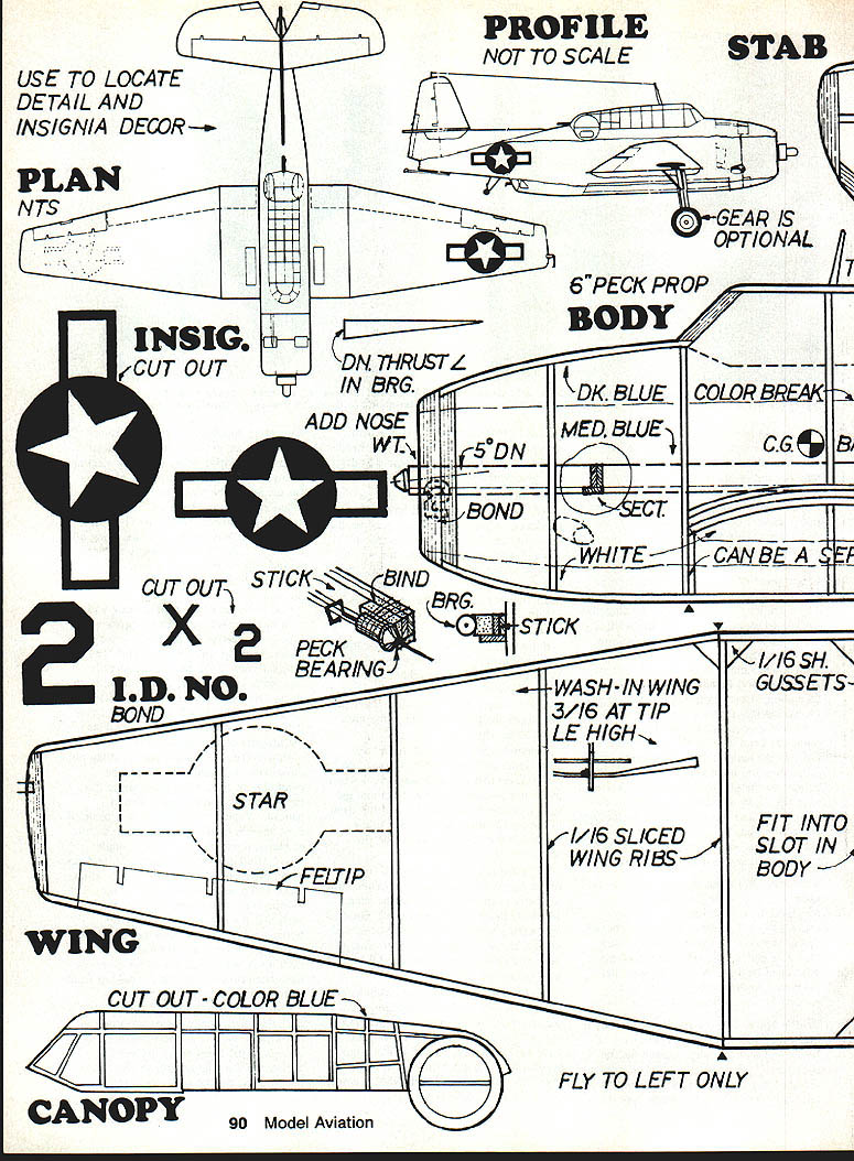
- Affix the nose bearing (mounted on a small offset piece) and the rear hook (made from the extra prop shaft) to the motor stick while it is still unattached. Glue the bearing with about 5° downthrust and no side thrust, using the plan to establish the angle. Keep glue out of the hole.
- Bind the bearing to the stick with a few tight turns of thread and reglue. Add the rear hook at the other end, inserting the small spur into the end of the stick and gluing it well. Note the ledge formed by the bottom strip must be on the right side of the model to fit the flat profile body.
Covering
- Remove all balsa frames from the plan so it can be used to prepare the tissue covering pieces.
- Cut three tissue pieces for the wing (they overlap at the dihedral joint), and one each for the stabilizer and the profile body-with-fin. Leave at least 1/2 in. oversize around all outlines. Tape them temporarily to the waxed-paper-covered plan, keeping tape outside the portions that will cover the model.
- Color the top of the profile body with a dark-blue marker following the plan lines. Color the belly under the wing with white acrylic paint (the example had slightly less white). Draw cowl flaps, exhaust, torpedo door, rudder hinge, and control outlines with a fine black felt-tip pen.
- Cut the white numerals from bond paper using the numeral patterns on the spare plan. Tape bond to a thin smooth cardboard, tape the printed patterns over it, and cut carefully with a fresh knife blade and small straightedge.
- Cut the star-and-bar insignia from the spare plan. Black may substitute for navy blue; for purists color bond paper with the blue marker before cutting.
- Cut the canopy pattern from the plan copy for later application.
- To apply paper insignia and numerals: flip cut pieces upside down on clean newspaper, spritz with 3M Spray‑Mount aerosol rubber cement (or a thin coat of Craft Bond), pick up pieces on the tip of an X‑Acto blade, flip them over, and place them on the appropriate spots using dotted lines visible through the tissue as a guide.
- To adhere tissue to frames: apply Craft Bond thinned one‑third with water to outlines and root ribs, then lay the tissue on top and smooth wrinkles.
- Cover the profile body on the left side only. Glue all uprights, outlines, and slot ribs to the covering. Recommended method: spot glue at the nose and tail first, confirm alignment, then lift the tissue and glue the top and belly of the frame. When glue sets, trim excess tissue with a sharp X‑Acto. Trim tissue from the stab and wing slots as well.
- Add the canopy, align carefully, and trim. Color the canopy frame to match the top of the profile body; a blue Sharpie may be easiest for slim frames.
Assembly
- Fit the stabilizer into its slot and square it up, sighting from the top and rear. Apply a drop of Hot Stuff CyA at the joints where the leading and trailing edges join the fin and hold until set.
- Slip the wing into the slot in the profile body and slide it forward so the center rib is inside the slot. Add the underwing piece if used.
- Tag-glue the bottom of the wing to the profile body. It's sufficient to glue at the leading and trailing edges—full rib attachment is not necessary.
- Glue the motor stick in place with a good fillet of glue where it meets the body and at the nose.
- Install the rubber motor on the motor stick over the prop shaft and secure it with the rear hook. Use a dab of CyA to hold the knot and wrap a few turns of ordinary sewing thread around the motor stick and knot to keep the motor from creeping.
- Balance the model by adding nose weight as required. Check the balance point under the wing roots on your fingertips and add clay or strip solder to reach the center of gravity shown on the plan. You will likely need some nose weight.
Flying
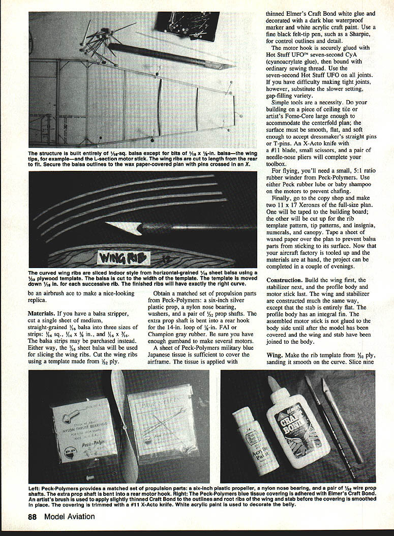
- Use a patient helper to pinch the prop hub and steady the model while you wind the motor from the rear. Keep the motor at an angle above the motor stick and wind in about 20–30 turns on a 5:1 winder.
- Stretch the motor out to about twice the rubber length and make a small loop to attach to the rear hook under the stabilizer. Carefully take the model from your helper by holding it under the wing by the prop tip and belly.
- Fly indoors in a gym or outdoors only in winds under about 10–15 mph. Strong winds tend to destroy a fragile model.
- Point the Avenger into the wind, release the prop, and step toward the airplane—do not throw the model. The model should spiral up in a wide leftward circle.
- Trimming adjustments:
- If it dives in, add up elevator by cracking the stab at the spar.
- If it flies right or straight, try adding left rudder.
- If it spirals in to the left, add more wash‑in to the left wing.
- If it stalls, add more nose weight.
- Make small adjustments and test conservatively until you achieve a good spiral climb.
True to the full‑scale prototype, this model glides like a brick—don't expect flight durations longer than 30–45 seconds. That's long enough for some thrilling aerial fantasy: pretend you're off to torpedo another ship.
Finishing and Decoration
- When satisfied with flights, decorate with the Xerox insignia, numerals, and dark‑blue markings shown on the plan.
- Use white acrylic on the belly and dark‑blue waterproof marker on top. Pick out detail work—cowl flaps, torpedo-bay doors, and other features—with a fine black felt‑tip.
- Add any optional realistic touches (tail arrestor hook, canopy detail) as desired.
You’ll find the Flying Aces Club No‑Cal Profile Scale Avenger a rewarding model to build and fly. It makes a nice display model as well as a good flier.
Transcribed from original scans by AI. Minor OCR errors may remain.

