
Bushfly
Functional .46-powered model is "just for the fun of it"
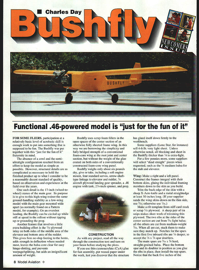
For some fliers, participation at a relatively basic level of acrobatic skill is enough work to put into something that is supposed to be fun. The Bushfly was put together with this "just for the fun of it" fraternity in mind.
The absence of a cowl and the semi-ultralight configuration resulted from an effort to keep the model as simple as possible. However, structural details are as complicated as necessary to hold the finished product up to what I consider a reasonably decent standard of quality, based on observation and experiences at the field over the years.
One such detail is the 17-inch (wheel-to-wheel) stance of the main gear. Its purpose is to give this high-wing trainer the same ground-handling stability as a low-wing model with the main gear mounted wide apart (as normally found on a Pattern model, for example). On an overshot landing, the Bushfly can be circled up while still at speed in the rollout without tipping up or grounding the prop.
Another feature that involves a little extra building effort is the 1/32 plywood inlay on both sides of the middle area of the elevator and the bottom area of the rudder. This gives firm, no-slop footing to the horns, adds strength in deflection where needed, leaves the balsa core clear for easy hinge-slotting, and prevents warpage/splitting, while adding an insignificant amount of weight.
The Bushfly uses scrap foam fillers in the open spaces of the center section of an otherwise fully sheeted frame wing. In this way we borrow the simplicity and fully bridged strength of a conventional foam-core wing at the root joint and center section, but without the weight of glue coated on both sides of a conventionally constructed foam-core wing panel.
Bushfly weighs only about six pounds dry, give or take, including a soft engine mount, four standard servos, arrow-shaft-type linkage to elevator and rudder, 1/4" aircraft plywood landing gear spreader, a .46 engine with tank, 2-1/4-inch spinner, and prop.
Specifications
- Type: RC Sport/trainer
- Wingspan: 61 inches
- Engine: .40–.46 two-stroke
- Functions: Throttle, elevator, rudder, ailerons
- Flying weight: ~6 pounds (approx.)
- Construction: Built-up
- Covering/finish: Silkspan and dope
Construction
As with any project, read all the way through the construction text and turn on your brain before studying the plans.
If you use thin cyanoacrylate (CyA) glue for fast assembly, put waxed paper under the work, lest you discover that the structure has glued itself down firmly to the workbench.
Some suppliers (Lone Star, for instance) sell 4–6-lb. very light sheet. Unless otherwise noted, all blocking and sheet in the Bushfly thicker than 1/32" is extra-light. For a few pennies more, some suppliers will select "dead straight" pieces when requested, such as the 1/4" medium balsa for the stab and elevator.
Wing
- Make a right and a left panel. Construct the frames integral with their bottom skins, gluing the individual framing members down to the skin as you build.
- Trim the back edge of the skin with a sharp X-Acto knife and a metal straightedge at least 30 inches long. (If your supplier sands the wing skins down on the thin side, use 3/32"; otherwise use 1/16".)
- Make a rib template from stiff card stock or scrap 1/32" plywood. A sharp pair of tin snips makes short work of trimming thin plywood. The two ribs at the sides of the center section are cut from 3/16" light balsa; all the others are cut from medium-weight 3/32". Cut a stack; make sure they match up. Notches for the spars in the first five inboard ribs are 1/16" deeper to accept the 5/32 x 3/16" spar doublers.
- The main spars are 3/16" x 3/8" hard, straight-grained balsa. Place the bottom spar and its doubler in position as you glue the ribs in place, then install the top spars. Note that the back five inches of the wing surface are built flat on the workbench to keep the panel twist-free.
- Save the rib template; later use it in laying out the wing saddle that fits the wing and holds 0° incidence.
- When assembling two panels to form a one-piece wing, the center section is filled between framing members with scrap foam. Small pieces of foam can be blocked out with a hacksaw blade and sanded to contour with a coarse sanding paddle; hot-wire cutting is not necessary. When gluing foam adjacent to wood, use epoxy or aliphatic-resin glues—some glues are chemically incompatible with foam and will make a mess.
- The back of the center section is faced with 1/16" plywood cut to match the dihedral. Drill to accommodate a 1/8" front hold-down dowel. Taper the back end of the dowel with a pencil sharpener; the tapered back end is anchored in a hole drilled in the front 1/16" plywood scab reinforcement where the spars meet at the root center. Predrill holes in plywood parts before gluing.
- Place the back scab at the root joint. 1/32" plywood also serves as the front face of the aileron servo well; the back face is also 1/32" plywood.
- Set up the two panels in a jig or otherwise support them so there is no twist within a panel; the root joint should be held at 0° incidence and the correct dihedral angle. Complete the center section, installing the dowel and the foam fills. Be sure the bottom skins fit neatly at the root where the foam fills meet to form the root joint, which is glued with 30-minute epoxy.
- Glue the 1/16" vertical-grained spar webbing in place before adding the top wing skin. Use slow-curing glue so you have time to apply it to the top framing surfaces of an entire panel before placing the skin in position and taping it down to the top edge of the front trimmer. A fully sheeted wing will take a permanent, stiff set—including any twist—so be sure it is true.
- Reinforce the center section with four-ounce glass cloth and epoxy.
- When rounding the leading edge of the wing panels, mark the line where the zero-incidence plane intersects the front face (use a soft-lead pencil). Round up and down to that line to maintain the incidence integrity of the wing. Use the same principle to form the tips.
- Adjustment of wing incidence can be done by shimming or sanding at the back edge of the wing saddle. Any such adjustment should be feathered at the front of the saddle, since the wing is fixed in non-adjustable position by the front hold-down dowel. Doublers are fitted maybe 1/8" below the saddle cut (with possible need for adjustment in mind: balsa sands easily; plywood doesn't).
- The ailerons are cut from 3/32" x 2" aileron stock trimmed to 3/4" x 1/4". That will leave the trailing edge just a tad less than 3/16" thick—leave it that way; it's good insurance against flutter. Use Goldberg (or equal) long, heavy-duty 3/32" piano-horn wires.
- A 1/4-20 tap and drill set will be needed to put threaded holes in the rear hold-down blocks, which can be cut from 1/4" aircraft plywood or 1/8" maple.
Tail Surfaces
- The rudder and fin are cut from 3/8" sheet; the stab and elevator are 1/4" sheet.
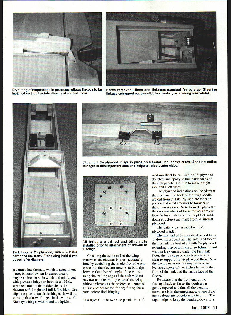
- The inlays in the middle of the elevator and the bottom of the rudder are cut from 1/32" plywood. Sand the areas to be worked down 1/32" using a ruler as a guide to keep the edges of the cut-out areas straight. Epoxy the plywood pieces to the surfaces and hold them securely with office binder clips while the epoxy cures.
- Install the hinges on the elevator, rudder, and ailerons. Slot the stab, fin, and wing so the control surfaces can be dry fitted. Note there is a cut-out in the rudder to allow the tailwheel.
Fuselage
- Cut the two side panels from 1/8" medium sheet balsa. Cut the 1/32" plywood doublers and epoxy them to the inside faces of the side panels. Be sure to make a right side and a left side.
- The plywood indications on the plans at the front and the back of the wing saddle are cut from 1/8" Lite Ply, and are the side portions of what amount to formers at these two stations. Note from the plans that the crossmembers of these formers are cut from 1/4" light balsa sheet, except that hold-down structures are made from 1/4" aircraft plywood.
- The battery bay is faced with 1/32" plywood inside.
- The firewall of 1/4" aircraft plywood has a 1° downthrust built in. The sides and top of the firewall are beefed up with 1/16" plywood extending maybe an inch or so behind it and with an L extending under the fuel tank floor, the top edge of which serves as a place to support the 1/16" plywood floor. Note the front barrier restraining the tank and leaving a space of two inches between the front of the tank and the inside face of the firewall.
- Be aware that the front end of the fuselage back as far as the doublers is gently tapered and that all the bending curvature is in the empennage, where there are no doublers to resist and distort it. The taper helps keep bending to a minimum and gives a more graceful contour. The extra-long tail blocking gives the stab and fin a more solid base for gluing.
- The main gear wheels are mounted on legs made by hacksawing a Great Planes .40-size aluminum gear into two parts, flattening the upper bends, rebending, and bolting the resulting legs to a 1/4" x 2" aircraft plywood gear support. This is not exactly leisure building; if you do not have a heavy-duty vise and solid workbench, you may need a little help with this chore.
- Before closing the belly of the empennage, install the elevator and rudder linkage. With the rudder and elevator dry fitted, the linkage can be installed pointing straight at the horns. If an inside antenna is desired, scavenge the tube from a flexi-cable set and route it back through the length of the tail. The antenna will thread into it without binding.
Covering
- The Bushfly was designed to permit the use of doped-on silkspan. For those not familiar: it is not silk but more like a fibrous tissue paper.
- Give the balsa surfaces three coats of clear dope. Cut pieces of silkspan as needed to cover the surfaces. Just prior to applying each piece, wet it by touching it down onto wet paper towels on the bottom of a flat baking pan. With a soft-bristle brush, paint the wet tissue onto the surface with clear dope. The dope strikes through the silkspan and sticks it to the surface. When dry, the water evaporates, shrinking the silkspan to a tight, smooth surface that hides the grain in the wood and will not bag or wrinkle when the color coats are applied. For maximum lightness, go easy on the color coats.
- Always apply dope in a well-ventilated workspace, like outdoors on a nice day.
Electronics and Fuel
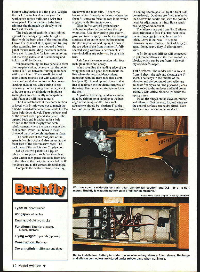
- The battery and receiver are taped together with a couple of turns of masking tape; the receiver on top with terminals exposed, and a little piece of corrugated cardboard sandwiched between them. This pack is encased in a single foam-rubber sleeve and secured in a bay built into the fuselage for this purpose. This compact vibration protection for battery and receiver has been used many times over the years without problems.
- The fuel tank is located back where the leverage arm from the center of fuel weight to the balance point is as short as possible, to keep the balance point from creeping rearward as fuel is burned off in flight. Wrap terrycloth toweling around the tank and tape it in place with continuous-coverage masking tape. This gives the unit a slick outside surface that slides nicely in place without bulking it up too large for the cowl, and gives adequate protection against fuel leakage.
- Note that the throttle linkage passes to the right of the tank and the steering linkage is under the tank floor, accessible through the 1/8" Lite Ply hatch under the nose.
Preflight
- Be sure that the balance point is not significantly behind the point indicated on the plans. Tail-heavy is bad news.
- Balance the model in roll by placing the skid on a tabletop, supporting the front end by the spinner, and adding weight to the high wingtip. This is normally needed to offset the imbalance of a side-mounted muffler.
Flying
Built straight, the Bushfly will compare favorably with most other trainers of its size and power when it's up in the blue; and on the ground it is considerably less troublesome and more accommodating than most.
Charles Day 6127 Knollwood Dr. Falls Church, VA 22041
Transcribed from original scans by AI. Minor OCR errors may remain.

